Table of Contents
Advertisement
Quick Links
Advertisement
Table of Contents

Related Manuals for Habey EMB-4500


Summary of Contents for Habey EMB-4500
- Page 1 EMB-4500 Owner's Manual Freescale ARM Cortex™-A9 Powered EPIC Motherboard...
- Page 2 Except for the accessories attached to the product as specified herein, what is contained in this user manual does not represent the commitments of Habey USA Company.~Habey USA Company reserves the right to revise this User Manual, without prior notice, and will not be held liable for any direct, indirect, intended or unintended losses and/or hidden dangers due to installation or improper operation.
-
Page 3: Safety Instructions
Safety Instructions 1.Please read this manual carefully before using the product. 2.Put all the unused or uninstalled boards or electronic components in a static dissipative surface or static shielding bag. 3.Always ground yourself to remove any static discharge before touching the board, to place your hands on grounding metal object for a while or wear a grounding wrist strap at all times. -
Page 4: Table Of Contents
Contents Section1 Product Introduction ....................1 1.1 Specification ........................1 Section 2 Motherboard Instructions ................... 3 2.1 Interfaces Location & Dimension .................. 3 2.2 Installation Steps ......................3 2.3 Jumper Settings ......................5 2.3.1 COM2 Jumper Setting(J1,J2,J3) ..............5 2.4 Interfaces Description ....................6 2.4.1 Serial Ports(COM1_COM5) ................ - Page 5 3.1.8 TF Card ......................20 3.1.9 SATA HDD ......................20 3.1.10 WIFI ....................... 20 3.1.11 3G ........................20 3.1.12 Ethernet ......................20 3.1.13 Audio Card ...................... 20 3.2Linux OS ........................20 3.2.1VGA ........................20 3.2.2 HDMI ....................... 20 3.2.3 LCD ......................... 21 3.2.4 USB .........................
-
Page 6: Packing List
Packing List Thanks for purchasing a Habey USA product. Please check the packing list when you open its package. If you find any defect components or anything damaged or lost, please contact your vendor ASAP. ■ EMB-4500 Motherboard 1 pcs... -
Page 7: Section1 Product Introduction
Section 1 Product Introduction 1.1 Specifications Dimension ●Dimension: 165mmX115mm Processor ●CPU: Onboard Freescale Cortex™-A9 i.MX 6.1GHz (Single-core/dual-core/ Quad Core CPUs) Memory ●Onboard RAM: default 1GB, DDRⅢ 800, Display ●Display port: LVDS, 2x HDMI ●LVDS: dual channel 24Bit LVDS with resolution up to 1920×1200@60Hz ●HDMI1: SiI9022A, maximum resolution: 1920x1080@60Hz ●HDMI2: i.MX6 CPU integrated, maximum resolution:1920x1080@60Hz Ethernet... - Page 8 ●Provide 1x Line-in, 1x Headphone port ●COM: 5x COM. COM2: RS232/RS422/RS485; COM1-5:RS232 ●Provide 8x USB 2.0: 2x standard USB2.0,1x mini USB OTG, 3x USB2.Omm pin header,MINI PCIE base with 1x USB, 1x USB WIFI module. ●Support two-way CAN BUS (optional) Expansion ●1x MINI PCIe supports WiFi/3G Module ●Onboard SIM card socket supports 3G network, to function by working with MINI PCIe 3G...
-
Page 9: Section 2 Motherboard Instructions
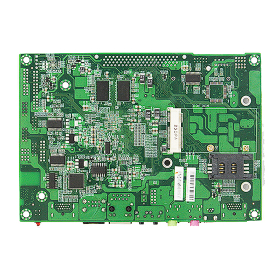
Section 2 Motherboard Instructions 2.1 Interfaces Location & Dimension Following picture illustrates the front interfaces location and the dimension of board EMB-4500. Please pay attention to the installation steps. Improper installation of some components may lead to system failure. Note: When installing the board, please wear anti-static gloves in case of any electrostatic damage caused during the installation. - Page 10 2.Install other expansion cards 3.Connect all signal line, cables, panel control circuits and power adaptor.
-
Page 11: Jumper Setting
Key components of this motherboard are Integrated circuit and these components could be easily damaged by electrostatic influence. So, before installing this unit, please always keep the following precautions in mind: 1. Hold the board by edges and don’t touch any components or plug and socket pins. 2.Wear anti-static gloves/wrist strap while touching the integrated circuit components, such as CPU, RAM, etc. -
Page 12: Interfaces Description
J1、J2 COM2 AS RS232 PORT COM2 AS RS422 PORT COM2 AS RS485 PORT 1-3,2-4 3-5,4-6 3-5,4-6 1-3,2-4 3-5,4-6 3-5,4-6 5-6 7-8 2.4 Interfaces Description Please read this manual carefully before installing any external connectors, in case of any damage to the motherboard! 2.4.1 Serial Ports (COM1_COM5) Board provides 5 serial ports. - Page 13 COM4、COM2 COM5、COM3 COM1 COM1/COM3/COM4/COM5: Signal Name 1、2、7、8 COM_RXD COM_RTS# COM_TXD COM_CTS# 9、10 COM2: RS232/RS422/RS485, Pins define: RS232(Default) RS422 RS485 DATA- DATA+ COM_RXD COM_RTS# COM_TXD COM_CTS#...
-
Page 14: Sata Port(Sata)
2.4.2 SATA Port (SATA) Board provides one standard 7+15Pin SATA port. SATA: Signal Name Signal Name 1、2 +3.3V +3.3V P13、P14 +3.3V... -
Page 15: Usb(Usb12, Usb34, Usb56)
2.4.3 USB (USB12, USB34, USB56) Board provides 8x USB2.0 ports: 2x standard USB2.0 ports; 1x Mini USB interface; 4x USB2.0mm Pin. MINI PCIE base with 1 USB. USB12 USB56 USB34 USB12: Signal Name 1, 2 3, 4 USB DATA- 5, 6 USB DATA+ 7, 8 USB34, USB56:... -
Page 16: Ethernet(Lan)
2.4.4 Ethernet (LAN) Board provides one PHY chip. Model No. AR8033. The yellow LED indicates data transfer status; the green LED indicates the network link status. RJ45 LAN LED Status: LILED(GREEN) Function ACTLED(YELLOW) Function 100/1000M Flash Data transfer No data 2.4.5 KEY (3x3) Board provides one 2×4Pin 3x3 keypad matrix, which is used to extend external keypad. -
Page 17: Audio(Audio, Line-Out, Mic-In)
K/M: Signal Name Signal Name 3.3V KEY_COL2 KEY_ROW2 KEY_COL7 KEY_ROW7 KEY_COL6 KEY_ROW6 2.4.6 Audio (AUDIO, Line-out, MIC-in) EMB-4500 adopts SGTL5000-XNAA3 audio controller chip. The green one is the audio output interface (Line-out). The pink one is Mic-in. -
Page 18: Audio(Audio, Line-Out, Mic-In)
Line-out MIC-in AUDIO: Signal Name Signal Name MIC1*P 管脚 LIN_L LIN_R LINE_OUT_L LINE_OUT_R 2.4.7 Display Interface (LVDS, HDMI1_HDMI2) Board provides 1x dual channel LVDS port and 2 HDMI HD display port. - Page 19 HDMI1 LVDS HDMI2 LVDS: Signal Name Signal Name VDD_PANEL VDD_PANEL 管脚 LVDS0_TX0_NEG LVDS1_TX0_NEG LVDS0_TX0_POS LVDS1_TX0_POS LVDS0_TX1_NEG LVDS1_TX1_NEG LVDS0_TX1_POS LVDS1_TX1_POS LVDS0_TX2_NEG LVDS1_TX2_NEG LVDS0_TX2_POS LVDS1_TX2_POS LVDS0_CLK_NEG LVDS1_CLK_NEG LVDS0_CLK_POS LVDS1_CLK_POS VCC5 VCC5 LVDS0_TX3_NEG LVDS1_TX3_NEG...
-
Page 20: Jtch)
LVDS0_TX3_POS LVDS1_TX3_POS VCC5 VCC5 2.4.8 (JTCH) JTCH: Signal Name Signal Name +3.3V 管脚 LVDS1_SCL LVDS0_SCL LVDS1_SDA LVDS0_SDA CAP_TCH_INT0 CAP_TCH_INT1 JLVDS Signal Name Signal Name +3.3V 管脚 BACKLIGHTON LVDS_VDD VCC5 L_BKLT_CTL LVDS_VDD +VIN +VIN... -
Page 21: Power Interface(Pwr, Rsasw, Pwrsw, Led1)
2.4.9 Power Interface ( PWR, RSASW, PWRSW, LED1 LED1 RSTSW PWRSW PWR: Signal Name +VIN... -
Page 22: J8, J14, J15, J16)
2.4.10(J8, J14, J15, J16) J14、J15 J8: 16 Bit GPIO Signal Signal Name Signal Name SD1_CMD EIM_CSD 管脚 SD1_CLK EIM_D23 SD1_DAT0 EIM_BCLK SD1_DAT1 SD2_CLK SD1_DAT2 NANDF_D7 ENET_RXD0 NANDF_D4 ENET_TXD0 NANDF_D5 SD2_CMD BUZZER J14/J15: Pins for TF card & INAND boot options Signal Name J14(3-4) SD3 TF boot... -
Page 23: Front Panel Connector(Jfp)
J14(5-6) SD4 INAND boot J15(1-2) SD4 INAND boot J15(7-8) SD4 INAND boot J15(5-6) SD4 INAND boot J16: Pins for Boot mode and Burn mode Signal Name J16(2-4) NORMAL BOOT J16(4-6) DOWNLOADER 2.4.11 Front Panel Connector (JFP) JFP is used to connect all function buttons and indicating LEDs on the front panel. JFP: Signal Name Signal Name... -
Page 24: Mini Pcie
Please follow the table below to connect, pay attention to the anode(+)and cathode(-), otherwise , some function can not be realized. POWER LED HDD LED RESET SW PWR SW 1) System Power LED Pins (Pin 1/2 for PWRLED) Connect system power LED cable with these pins(pin 1 is LED anode)When system is power on, power LED is on;When system is power off, power LED is off. -
Page 25: 4-Wire Resistance Touch(J4)
J5: Signal Name Signal Name VCC5 VCC5 CAN1_H CAN2_H CAN1_L CAN2_L 2.4.14 4-wire Resistance Touch (J4) The motherboard provides one 4-wire resistance touch J4 (optional). J4: Signal Name TOUCHSCREEN_x+ TOUCHSCREEN_X- TOUCHSCREEN_Y+ TOUCHSCREEN_Y-... -
Page 26: Section 3 Software Instructions
Section 3 Software Instructions 3.1 Android OS 3.1.1VGA VGA output is unsupported temporarily. 3.1.2 HDMI 2x HDMI output by changing u-boot environment variables Setting instructions: 1.Input following command when system is entering the u-boot command line interface: setenv bootargs console=ttymxc0,115200 androidboot.console=ttymxc0 vmalloc=400M init=/init... -
Page 27: Sd Card
3.1.7 SD Card Unsupported 3.1.8 TF Card TF Card auto mount directory:/dev/extsd/ 3.1.9 SATA HDD Mount directory is customized as per customers’ demands 3.1.10 WIFI Support, how to operate, please refer to android interface 3.1.11 3G 3G Driver is customized as per customers’3G module 3.1.12 Ethernet Support, how to operate, please refer to android interface 3.1.13 Audio Card... - Page 28 3.2.3 LCD Support LVDS LCD output. Driver is customized as per customers’ LCD screen. 3.2.4 USB Support 3.2.5 COM Device nodes:/dev/ttymxc0~/dev/ttymxc4 3.2.6 CAN No test 3.2.7 SD Card Unsupported 3.2.8 TF Card Support, need to mount for testing 3.2.9 SATA HDD Support, need to mount for testing 3.2.10 WIFI Support, need iwlist iwconfig for testing...
-
Page 29: Appendix
Appendix Appendix 1: Glossary ACPI Advanced Configuration and Power Management。ACPI specifications allow O/S to control most power of the computer and its add-ons BIOS Basic input/output system, it is a kind of software including all in/out control code interface in PC. - Page 30 DIMM Dual-Inline-Memory-Modules, it is a small circuit board with memory chipset providing 64 bit memory bus width. DRAM Dynamic Random Access Memorizer, it is a normal type of memory often with a transistor and a capacitance to store 1 bit. With the development of the technology, more and more types of DRAM with different specifications exist in computer applications.
- Page 31 the system, including RAM, keyboard, hard disk driver etc. to check if all the components are in normal situation and work well. PS/2 A keyboard & mouse connective interface specification developed by IBM.PS/2 is a DIN interface with only 6PIN; it also can connect other devices, like modem It is the Universal Serial Bus for short.
- Page 32 21015 Commerce Pointe Drive, Walnut, CA www. habeyusa.com Copyright@2013. Habey USA. All Rights Reserved. Version 1.0...
Need help?
Do you have a question about the EMB-4500 and is the answer not in the manual?
Questions and answers