Table of Contents
Advertisement
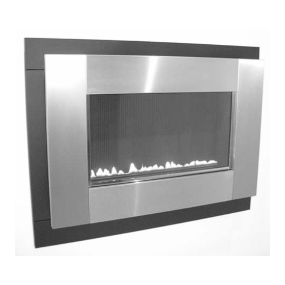
PLASMA
MODEL : F500070
UNVENTED WALL MOUNTED ROOM HEATER
INSTALLATION INSTRUCTIONS
(Para Instrucciones en español, ver la página 12)
Issue E-15/06
FOR USE ONLY WITH DECORATIVE TYPE
UNVENTED ROOM HEATERS.
WARNING: IMPROPER INSTALLATION, ADJUSTMENT,
ALTERATION, SERVICE OR MAINTENANCE CAN CAUSE
INJURY OR PROPERTY DAMAGE.
MANUAL.
FOR
ASSISTANCE
INFORMATION CONSULT A QUALIFIED INSTALLER,
SERVICE AGENCY OR THE GAS SUPPLIER.
WARNING: DO NOT BUILD A WOOD FIRE. DO NOT
BURN WOOD OR OTHER MATERIAL IN THESE
APPLIANCES.
This appliance may be installed in an aftermarket,
permanently located, manufactured (mobile) home,
where not prohibited by local codes.
The appliance is only for use with the type of gas
indicated on the rating plate. This appliance is not
convertible for use with other gases.
REFER TO THIS
OR
ADDITIONAL
1
Installer And Consumer Are
To Retain The Appliance
Manual With The Installed
WARNING: IF THE INFORMATION IN THIS MANUAL
IS NOT FOLLOWED EXACTLY, A FIRE OR
EXPLOSION MAY RESULT CAUSING PROPERTY
DAMAGE, PERSONAL INJURY OR LOSS OF LIFE.
Do not store or use gasoline or other flammable
vapors or liquids in the vicinity of this or any other
appliance.
WHAT TO DO IF YOU SMELL GAS
• DO NOT light any appliance.
• DO NOT touch any electrical switches.
• DO NOT use any phone in your building.
• Immediately call your gas supplier from a neighbor's
phone.
Follow your gas suppliers instructions.
• If your gas supplier cannot be reached, call the fire
department.
Installation and service must be performed by a
qualified installer, service agency or the gas supplier.
This is an unvented gas-fired heater. It uses air
(oxygen) from the room in which it is installed.
Provisions for adequate combustion and ventilation air
must be provided. Refer to Combustion and Ventilation
Air Section, Page 3.
INSTALLER:
LEAVE THIS MANUAL WITH THE APPLIANCE.
CONSUMER:
RETAIN THIS MANUAL FOR FUTURE REFERENCE.
Due to high temperatures, the appliance should be
located out of traffic and away from furniture or
draperies. Do not place clothing or other materials on or
near this appliance.
Appliance
Advertisement
Table of Contents

Subscribe to Our Youtube Channel
Summary of Contents for Charmglow Plasma F500070
-
Page 1: Installation Instructions
Installer And Consumer Are To Retain The Appliance Manual With The Installed Appliance PLASMA MODEL : F500070 UNVENTED WALL MOUNTED ROOM HEATER WARNING: IF THE INFORMATION IN THIS MANUAL IS NOT FOLLOWED EXACTLY, A FIRE OR EXPLOSION MAY RESULT CAUSING PROPERTY DAMAGE, PERSONAL INJURY OR LOSS OF LIFE. -
Page 2: Table Of Contents
TABLE OF CONTENTS 2.0 INVENTORY QUANTITY DESCRIPTION Section Contents Page No. Firebox and burner assembly General Information Installation and operating instructions Inventory Decorative frame assembly Appliance Data Screw and wall plug pack Important Safety Information Wall mounting plate Codes Rubber grommet Combustion and Ventilation Air Fitting template Site Requirements... -
Page 3: Important Safety Information
4.0 IMPORTANT SAFETY INFORMATION (continued) 6.0 COMBUSTION AND VENTILATION AIR • Children and adults should be alerted to the hazard of high surface This heater shall not be installed in a confined space or unusually tight temperature and should stay away to avoid burns or clothing ignition. construction unless provisions are provided for adequate combustion and ventilation air. -
Page 4: Site Requirements
UNCONFINED SPACE OR IF THE BUILDING IS OF Under no circumstances should any electrical equipment e.g. plasma UNUSUALLY TIGHT CONSTRUCTION, PROVIDE ADEQUATE screen TV sets etc. be positioned on the wall above the appliance. The appliance is designed to be wall mounted alone and not in conjunction with COMBUSTION AND VENTILATION AIR BY ONE OF THE any type of combustible fire surround. -
Page 5: Preparing The Appliance
Pipes must be secured using suitable clips and protected against Mark the positions shown as “Plasma/Capella/Radium fixing points on corrosion. Ideally factory finished protected pipework and fittings should be the wall. -
Page 6: Checking The Burner
9.0 MOUNTING THE APPLIANCE - continued Insert lower mounting screws into the lower wall plugs through the corresponding depressed holes in the lower part of the back panel. Do not tighten fully. Figure 6 Before tightening the wall mounting screws fully, at this stage it is recommended to check the horizontal alignment of the appliance with a spirit level, as small adjust- ments can still be made if necessary. -
Page 7: Spark Gap
Lay out the dustsheet and tools. 14.0 GAS PRESSURE CHECK - continued Remove the front section of the frame by following section 8.0 Remove the glass door assembly (4 screws) and clean Remove the valve cover by unscrewing the two retaining screws. carefully. -
Page 8: Pilot Assembly
Ignite the fire as per the operating instructions, and run at maximum 18.0 SERVICING THE BURNER - continued setting for 15 minutes. Position gas sample probe directly over a cata- The pilot assembly is a non-serviceable item and should not be taken lyst via the outlet grille, on top of the appliance. -
Page 9: Lighting Instructions
FOR YOUR SAFETY READ BEFORE LIGHTING WARNING: IF YOU DO NOT FOLLOW THESE INSTRUCTIONS EXACTLY, A FIRE OR EXPLOSION MAY RESULT CAUSING PROPERTY DAMAGE, PERSONAL INJURY OR LOSS OF LIFE. • Immediately call your gas supplier from a neighbor’s phone. This heater has a pilot which must be lit by hand. -
Page 10: Troubleshooting Guide
25.0 TROUBLESHOOTING GUIDE Fire sparks but pilot does not light No gas to fire, check isolators are open. Pipe work blockage, clean out. Air not fully purged, re purge supply or wait longer. Spark grounding to metal work, reset gap correctly. Blocked pilot, clean out internally. - Page 11 27.0 POSITIONING OF FIELD REMOVABLE PARTS WARNING: FAILURE TO POSITION Figure 12 THE PARTS IN ACCORDANCE WITH THESE DIAGRAMS OR FAILURE TO USE ONLY PARTS SPECIFICALLY APPROVED WITH THIS HEATER MAY RESULT IN PROPERTY DAMAGE OR PERSONAL INJURY. Figure 12 : Removal and refitting of glass door assembly and burner assembly.
Need help?
Do you have a question about the Plasma F500070 and is the answer not in the manual?
Questions and answers