Table of Contents
Advertisement
Advertisement
Table of Contents

Related Manuals for COBHAM Sailor SP3530

Summary of Contents for COBHAM Sailor SP3530
- Page 1 SAILOR SP3530 Portable VHF ATEX User manual...
- Page 2 Emergency procedure • T urn the knob at the top of the radio clockwise. The display lights up s howing the last used channel and the battery level. • S elect channel 16 (Distress or Safety), press the 16/C key. • P ress the PTT and say: - “MAYDAY, MAYDAY, MAYDAY”, - “This is”..ships name repeated three times - - “MAYDAY” - “This is”..ships name and call sign, - The ship’s position in latitude and longitude or other reference to a known geographical location, - The nature of distress and assistance wanted, - Any other information which might facilitate the rescue. - “OVER” • R elease PTT and listen for answer.
- Page 3 IMPORTANT INFORMATION Safe use of ATEX equipment: • Do not change the battery in wet or humid environments. • Always keep battery connectors dry and clean. • Use only with Sailor ATEX approved accessories. Alternatively ATEX approved accessories in compliance with the accessory connector ATEX specification may be used. • Do not change accessories in wet or humid enviroments. • Do not charge the battery in hazardous area. • For charge of battery use Part no: 403505A - ATEX CH3505 Compact Charger, Part no: 403507B - ATEX CH3507 Single Position Charger or Part no: 403508B - ATEX CH3508 Dual Position Charger • Use only battery type Sailor B3503 or B3504. • Do not use a mechanically damaged radio. • Unpacking of the radio and accessories and the removal of the protective film in front of the display window must not take place in the ATEX protected area. 99-127722-B 0850...
- Page 5 Thrane & Thrane A/S is not responsible for the content or accuracy of any translations or reproductions, in whole or in part, of this manual from any other source. Thrane & Thrane A/S is trading as Cobham SATCOM. 1340...
- Page 6 Precautions Avoid water and salt in the I/O connector and keep it clean frequently. Only use original Thrane & Thrane battery packs. Make sure they are clean and dry before attaching the transceiver. Be careful not to damage any gaskets. Only use the original Thrane &...
- Page 7 Training information SAILOR SP3530 ATEX VHF is designed for "occupational use only". It must be operated by licensed personnel only. The SP3530 complies with the FCC RF exposure limits for "Occupational Use Only". • FCC OET Bulletin 65 Supplement C, evaluating compliance with FCC guidelines for human exposure to radio frequency electromagnetic fields.
-
Page 9: Table Of Contents
Chapter 1 Introduction Your ATEX VHF ..............1 Performance ............... 2 Channels ................2 Chapter 2 Operation Controls ................5 Keys and buttons ..............5 The display .................7 Using the VHF ..............8 Basic functions ..............8 Other functions ..............11 Chapter 3 Batteries Battery level indication ............. - Page 10 Chapter 5 Equipment and accessories External equipment ............27 List of equipment .............. 27 Connecting external equipment ........27 Impact on radio operation ..........28 Accessorie connector ............28 Accessories ............... 29 List of accessories .............29 Attaching and removing the belt clip .........31 Attaching the lanyard ............31 Chapter 6 Troubleshooting Displaying errors ..............
-
Page 11: Chapter 1 Introduction
Chapter 1 Introduction Your ATEX VHF The SP3530 ATEX VHF is designed for flexibility in daily use. It connects easily to external equipment like headsets and fist mikes, making the SP3530 suitable for any noisy environment. Main features: Unique man machine interface, an excellent grip even with gloves, and large tactile buttons. -
Page 12: Performance
Introduction Performance For best performance of the transceiver keep the following in mind: • Keep clear of metal environment. • Hold the transceiver vertically and 10 cm from lips and push the PTT when transmitting. • In receive mode carry the transceiver vertically with belt clips. •... - Page 13 Introduction Channel modes The notes in the following sections list the channel restrictions that apply for each channel mode. For information on how to select a channel mode, see Entering and using Configuration mode on page 19 and CHAN on page 20. National frequency regulations shall always be respected and might operation for this type of equipment restrict...
- Page 14 Introduction Canadian channels Notes: • Tx power is limited to 1 W on channels 15, 17, 20, 65, 66 and 77. • The channels 19, 22, 63, 75, 76 and 81 cannot be selected. • The Weather channels (CA W-ch. in the channel table) can only be used in Rx direction.
-
Page 15: Controls
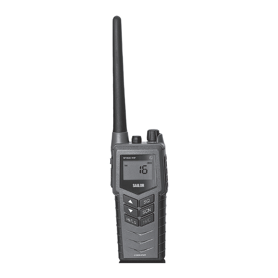
Chapter 2 Operation Controls Keys and buttons 1. On/off/volume 2. Light/Lock 3. Push To Talk (PTT) 4. Up key 5. Down key 6. Hi/Lo output power 7. Squelch 8. Scan 9. Priority channel (16)/ Call channel 10. Loudspeaker/microphone 0845... - Page 16 Operation Key presses Pressing and holding certain keys gives access to additional functions, shown in the table below. Extra long Short press Long press press (1 beep) (2 beeps) (3 beeps) Show next available Run through available Run through item in the list (up or items, or available down).
-
Page 17: The Display
Operation The display The display holds various fields of information, explained below. 1. Current working channel. 2. Current channel mode. 3. “Lo”: Reduced transmitter power. Full transmitter power is not shown in display. 4. Dual/Triple watch activated. 5. Current working channel is marked for scanning. 6. -
Page 18: Using The Vhf
Operation Using the VHF Basic functions Note Before using the radio, mount the antenna at the top of the radio. The antenna is delivered with the radio. Switching the radio on and off • To switch the radio on, turn the knob at the top of the radio clockwise. -
Page 19: Adjusting The Volume
Operation Activating a call To activate a call to the selected channel, press and hold the PTT button on the side of the radio. The radio transmits as long as the PTT button is pressed. A small Tx sign next to the channel num- ber indicates when the radio is in transmit mode. - Page 20 Operation Using Dual/Triple watch • To activate Dual/Triple watch, press the SCN key. The display shows “Dual” or “Tri” at the top and “16” at the bottom right. The radio toggles between the selected channel and channel 16 in Dual watch. In Triple watch, the radio shifts between channel 16, the call channel and the selected channel.
-
Page 21: Other Functions
Operation Other functions Programming the Call channel To program the Call channel, do as follows: 1. Press and hold 16/C until the current Call channel number is flashing. 2. Select the channel with or . 3. Press 16/C to confirm within 3 seconds. Programming the scanning memory To add a channel to the scanning memory, select the channel and then press and hold the SCN key until the display shows MEM at the top. - Page 22 Operation transmitting is prohibited (reporting "BUSY") if a (silent) carrier containing any sub-tone is active on the channel while pressing PTT Channels programmed with CTCSS will have a clear identification in the service field, e.g. "CTCSS 22", while selected. Not all channels are allowed for CTCSS use.
- Page 23 Operation Note Prior to any initiation of scrambling, the operator must always identify the calling station in clear voice (unscrambled) on that channel. Use of scrambling may also be restricted by national laws. Narrow band operation The radio is prepared for narrow band operation. If narrow band operation is selected (see BAND on page 25), the number of channels are doubled in the maritime channels, according to international recommendations.
- Page 24 Operation “ALIVE” function is also deactivated when • The channel is changed. • The radio is turned OFF and ON again. • Watch or scanning is enabled. • Squelch is open. Refer to ALIVE on page 25 1211...
-
Page 25: Chapter 3 Batteries
Chapter 3 Batteries Battery level indication When the battery level is low, you should recharge the battery. The radio display shows the battery status. When the battery symbol is empty and flashing, the battery should be recharged as soon as possible. Removing and inserting the battery pack To remove the battery pack, do as follows: 1. -
Page 26: The Battery Charger
Batteries The battery charger The chargers has two compartments. CH3505 • A compartment for recharging the battery alone or while attached to the radio. CH3507 • A rear compartment only for storing a spare battery. It does not have a charger function. •... -
Page 27: Recharging The Battery
Batteries When mounting the charger, make sure it is placed in a dry place and away from direct sunlight. The charger is not waterproof. Connecting to power The charger can be supplied from DC or from AC using an AC/DC converter. - Page 28 Batteries Charging time with emtpy battery: VHF off approx. 4 hours, VHF on: approx. 5 hours. The battery indicator on the radio display indicates if the radio is placed in the charger while radio and charger are both powered. 0845...
-
Page 29: Chapter 4 Configuring The Radio
Chapter 4 Configuring the radio Configuration mode Entering and using configuration mode Note The radio is not operational in configuration mode. • To enter configuration mode, press and hold the Light/Lock button while turning on the radio. The bottom line of the display shows the current menu item/setting. •... -
Page 30: List Of Configuration Settings
Configuring the radio List of configuration settings The following settings are available in configuration mode. Name Values Description LIGHT Only Light/Lock button activates the backlight. All keys and buttons, except PTT and volume control, activate the backlight. CHAN International channels. US channels. - Page 31 Configuring the radio Name Values Description SLEEP Enable sleep mode (to minimize power consumption). Sleeps for periods of 1 second after 15 seconds of idle mode. Idle mode is: no signal detected and no operation of the radio. Disable sleep mode. CONTRST 1, 2, 3, 4, 5 Contrast.
- Page 32 Configuring the radio Name Values Description TIME A long press on SQ opens squelch. The squelch level resumes to setting 3 seconds after SQ is released. A long press on SQ opens squelch. The squelch level resumes to setting as soon SQ is released. WORK If the distress or call channel is selected using ...
- Page 33 Configuring the radio Name Values Description 1 2 3 4 5 6 7 8 9 In ATIS programming mode: • Select the digit position with the Light/Lock button. • Select the digit with • Press Light/Lock to confirm programming. Note: All digits must be programmed.
- Page 34 Configuring the radio Name Values Description SUBC SUBC disabled. Squelch opens on all received signals. 1, 2, ..., 38 Sub-tone carrier ID. Squelch opens if the received signal contains the desired subtone. During transmission the sub-tone with the corresponding ID is generated.
- Page 35 Configuring the radio Name Values Description SCRM Scrambler disabled. Activate scrambling on working channel. Two radios on the same channel and with scrambling enabled, can have a certain level of privacy. Note that if you choose this option, the radio immediately exits configuration mode and starts scrambling on the working channel.
- Page 36 Configuring the radio Name Values Description ADD NAME A-Z, 0-9 Makes it possible to name the channels. The name must contain a maximum of 9 characters, use only capital letters, digits and spaces. Note: The name appears in the service line on the display.
-
Page 37: Chapter 5 Equipment And Accessories
Chapter 5 Equipment and accessories External equipment List of equipment The following equipment can be connected to the radio: • SAVOX C400AV Push-To Talk unit • SAVOX C500 Fist Mike • SAVOX NC/400 Noise-com • SAVOX HC-E Helmet-com • SAVOX K53004 Helmet unit •... -
Page 38: Impact On Radio Operation
Equipment and accessories When external equipment is connected to the radio, the right side of the display will show a headset. Impact on radio operation The external equipment can have a built-in PTT button, speaker and microphone. Thus a connection has per default the following impact on the radio operation: •... -
Page 39: Accessories
Equipment and accessories Accessories List of accessories The following accessories are delivered with your radio: Accessory Part number ATEX Secondary battery (blue, rechargeable), B3504 403504A ATEX Compact Charger, CH3505 403505A AC/DC converter, length 150cm (100-240V~ /12VDC out) 88-125538 12-24VDC Connection cable, length 150cm 37-124381 Belt clip 62-124320... - Page 40 Equipment and accessories Accessories you may buy Accessory Part number ATEX Charger, CH3507 403507B ATEX Dual Position Charger CH3508 403508B ATEX Leather Case with shoulder strop 403500-207 Leather Case Warning! The display must always be kept away from the body to reduce the RF explosure when body worn.
-
Page 41: Attaching And Removing The Belt Clip
Equipment and accessories Attaching and removing the belt clip To attach the belt clip, slide the belt clip upwards into the rails at the back of the radio until it locks. To remove the belt clip, press the projection at the top of the belt clip to release the lock and slide the belt clip downwards out of the rails. - Page 42 Equipment and accessories 0845...
-
Page 43: Chapter 6 Troubleshooting
Chapter 6 Troubleshooting Displaying errors Some errors result in an error message in the display. These error messages are listed below. Display text Problem Type Actions The battery voltage is Severe. Change/recharge below a critical level, Radio is non- the battery. EMPTY BAT where further operation functional. - Page 44 Troubleshooting 0845...
-
Page 45: Technical Specifications
Appendix A Technical specifications Technical data SP3530 General Item Specification Rx frequency range, landmobile 148.000 - 174.000 MHz Tx frequency range, landmobile 148.000 - 174.000 MHz Rx frequency range, maritime 155.000 - 163.425 MHz Tx frequency range, maritime 155.000 - 161.450 MHz Modulation 25 kHz 16K0G3E... -
Page 46: Transmitter
Technical specifications Item Specification Water ingress protection IP67 Frequency stability Better than ±0.7 kHz Weight with emergency battery 370g Transmitter Item Specification RF output power 2 W /1 W RF output power, Canada 1.7 W ±0.7 dB / 0.8 W ±1 dB Max deviation 25 kHz ±5 kHz... - Page 47 Technical specifications Item Specification Intermodulation 25 kHz > 68 dB 12.5 kHz > 65 dB Spurious response > 70 dB Adjacent channel selectivity 25 kHz > 70 dB 12.5 kHz > 60 dB Audio output, internal 0.25 W at 10% dist. Audio output, external 0.25 W/8 ohm 0740...
-
Page 48: Battery Life Guidelines
Technical specifications Battery life guidelines New batteries should be placed in the charger CH3505, CH3507 Note or CH3508 for minimum 12 hours first time. During daily use, always keep the battery fully charged and away from hot areas. Keep the battery terminals dry and clean. Never discharge beyond the specifications of the battery. -
Page 49: Dimensional Drawing, Transceiver
Technical specifications Dimensional drawing, transceiver 0845... -
Page 50: Dimensional Drawing, Chargers
Technical specifications Dimensional drawing, chargers CH3505 70.4 Mounting Possibillities Desktop mounting, top view Wall mounting, rear view 0845... - Page 51 Technical specifications CH3507 and CH3508 Mounting Possibillities Desktop mounting, top view Wall mounting, rear view 0845...
-
Page 52: Declaration Of Conformities
Thrane & Thrane A/S Lundtoftegårdsvej 93D, DK-2800 Kgs. Lyngby, Denmark Place and Date Aalborg, 20 June 2013 Svend Åge Lundgaard Jensen Document number: 99-129011-C Thrane & Thrane A/S trading as Cobham SATCOM Lundtoftegårdsvej 93D DK-2800 Kgs. Lyngby, Denmark · ·... - Page 53 Thrane & Thrane A/S Lundtoftegårdsvej 93D, DK-2800 Kgs. Lyngby, Denmark Place and Date Aalborg, 02. October 2013 Svend Åge Lundgaard Jensen Document number: 99-128497-C Thrane & Thrane A/S trading as Cobham SATCOM Lundtoftegårdsvej 93D DK-2800 Kgs. Lyngby, Denmark · ·...
- Page 54 Technical specifications 0929...
- Page 55 Technical specifications 0929...
- Page 56 Technical specifications 0929...
-
Page 57: Attention
Appendix B Attention Goretex Membran To keep the ATEX VHF watertight, is it very important that the goretex membran behind the label under no circumstances must be damaged or removed. 0929... - Page 58 Attention 0845...
- Page 60 98-124306-G www.cobham.com/satcom...
Need help?
Do you have a question about the Sailor SP3530 and is the answer not in the manual?
Questions and answers