Table of Contents
Advertisement
Advertisement
Table of Contents

Related Manuals for COBHAM SAILOR SP3500 Series


Summary of Contents for COBHAM SAILOR SP3500 Series
- Page 1 SAILOR SP3560 Portable UHF ATEX User manual...
- Page 3 IMPORTANT INFORMATION Safe use of ATEX equipment: • Do not change the battery in wet or humid environments. • Always keep battery connectors dry and clean. • Use only with Sailor ATEX approved accessories. Alternatively ATEX approved accessories in compliance with the accessory connector ATEX specification may be used. • Do not change accessories in wet or humid enviroments. • Do not charge the battery in hazardous area. • For charge of battery use Part no: 403505A - ATEX CH3505 Compact Charger, Part no: 403507B - ATEX CH3507 Single Position Charger or Part no: 403508B - ATEX CH3508 Dual Position Charger • Use only battery type Sailor B3503 or B3504. • Do not use a mechanically damaged radio. • Unpacking of the radio and accessories and the removal of the protective film in front of the display window must not take place in the ATEX protected area. 99-127722-B 0850...
- Page 5 Thrane & Thrane A/S is not responsible for the content or accuracy of any translations or reproductions, in whole or in part, of this manual from any other source. In the event of any discrepancies, the English version shall be the governing text. Thrane & Thrane A/S is trading as Cobham SATCOM. 1711...
- Page 6 Precautions Avoid water and salt in the I/O connector and keep it clean frequently. Only use original Thrane & Thrane battery packs. Make sure they are clean and dry before attaching the transceiver. Be careful not to damage any gaskets. Only use the original Thrane &...
- Page 7 Training information SAILORSP3560 ATEX UHF is designed for to be operated safely. It must be operated by licensed personnel only. The SP3560 complies with the uncontrolled RF exposure limits. • FCC OET Bulletin 65 Supplement C, evaluating compliance with FCC guidelines for human exposure to radio frequency electromagnetic fields.
- Page 8 Power settings Power settings are adjusted at the factory. The settings for the normal "High" power and the reduced "Low" power are saved and locked in the radio and is not accessible for the user. The user is not able to change any of the preset power settings.
-
Page 9: Table Of Contents
Contents Chapter 1 Introduction Your ATEX UHF ..............1 Performance ................ 2 Channels ................2 Chapter 2 Operation Controls ................5 Keys and buttons ..............5 The display .................7 Using the ATEX UHF ............8 Basic functions ..............8 Other functions ..............11 Chapter 3 Batteries Battery level indication ............. - Page 10 Chapter 5 Equipment and accessories External equipment ............27 List of equipment .............. 27 Connecting external equipment ........28 Impact on radio operation ..........29 Accessorie connector ............29 Accessories ............... 30 List of accessories .............30 Attaching and removing the belt clip ........ 32 Attaching the lanyard ............
-
Page 11: Chapter 1 Introduction
Channel read-out function for audible feedback of channel name in headset upon channel change A lanyard and belt clip included. A huge accessory program comes with the SAILOR SP3500 series. Please find the nearest SAILOR distributor on www.cobham.com. 1505... -
Page 12: Performance
Introduction Performance For best performance of the transceiver keep the following in mind: • Keep clear of metal environment. • Hold the transceiver vertically and 5 cm from lips and push the PTT when transmitting. • In receive mode carry the transceiver vertically with belt clips. •... - Page 13 Introduction Channel designator Recommendation ITU-R Frequency (preprogrammed) M.1174-3 457.525 MHz 457.550 MHz 457.575 MHz Table 2: Additional frequencies for 12.5 kHz use Channel designator Recommendation ITU-R Frequency (preprogrammed) M.1174-3 467.5375 MHz 467.5625 MHz 457.5375 MHz 457.5625 MHz Table 3: Duplex frequencies for use with repeaters only (25 kHz or 12.5 kHz use) Channel designator...
- Page 14 Introduction Channel designator Repeater RX Frequency Repeater TX Frequency (preprogrammed) 467.575 MHz 457.575 MHz 467.5375 MHz 457.5375 MHz 467.5625 MHz 457.5625 MHz The channel designators are defaulted to the letter formats “A” (25 kHz frequency separation) or “A “ (12.5 kHz frequency separation). Any additional explanatory naming can be added (see ADD NAME in Chapter 4 Configuring the radio on page 19.
-
Page 15: Controls
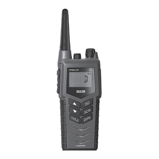
Chapter 2 Operation Controls Keys and buttons 1. On/off/volume 2. Light/Lock 3. Push To Talk (PTT) 4. Up key 5. Down key 6. Hi/Lo output power 7. Squelch 8. Scan 9. D/P0 quick channel select 10. Loudspeaker/microphone 0845... - Page 16 Operation Key presses Pressing and holding certain keys gives access to additional functions, shown in the table below. Extra long Short press Long press press (1 beep) (2 beeps) (3 beeps) Show next available Run through available Run through item in the list (up or items, or available down).
-
Page 17: The Display
Operation The display The display holds various fields of information, explained below. 1. Current working channel. 2. “Lo”: Reduced transmitter power. Full transmitter power is not shown in display. 3. Dual watch activated. 4. Current working channel is marked for scanning. 5. -
Page 18: Using The Atex Uhf
Operation Using the ATEX UHF Basic functions Before using the radio, mount the antenna at the top of the Note radio. The antenna is delivered with the radio. Switching the radio on and off • To switch the radio on, turn the knob at the top of the radio clockwise. - Page 19 Operation Activating a call To activate a call to the selected channel, press and hold the PTT button on the side of the radio. The radio transmits as long as the PTT button is pressed. A small TX sign next to the channel num- ber indicates when the radio is in transmit mode.
- Page 20 Operation Using Dual watch (requires priority channel is programmed) • To activate Dual watch, press the SCN key. The display shows “Dual” at the top and “D” at the bottom right. The radio toggles between the selected channel and channel D (if channel D is programmed as the priority channel).
-
Page 21: Other Functions
Operation Other functions Programming the scanning memory To add a channel to the scanning memory, select the channel and then press and hold the SCN key until the display shows MEM at the top. To remove a channel from the scanning memory, select the channel and then press and hold the SCN key until the MEM sign disappears from the display. - Page 22 Operation Scrambler On channels where it is allowed, you can set up voice scrambling, using configuration mode (see SCRM on page 24). Please note that if the radio is operating with scrambling on a channel, it is impossible to communicate with other radios that are not programmed with the same scrambler code.
- Page 23 Operation Alive beep To enable “ALIVE” function do as follows: 1. Select the channel where ALIVE function is desired to be transmitted. 2. Press and hold the Hi/Lo until you see “ALIVE ON” on the radio display. It takes approx. a second. 3.
- Page 24 Operation 1211...
-
Page 25: Chapter 3 Batteries
Chapter 3 Batteries Battery level indication When the battery level is low, you should recharge the battery. The radio display shows the battery status. When the battery symbol is empty and flashing, the battery should be recharged as soon as possible. Removing and inserting the battery pack To remove the battery pack, do as follows: 1. -
Page 26: The Battery Chargers
Batteries The battery chargers The chargers has two compartments. CH3505 • A compartment for recharging the battery alone or while attached to the radio. CH3507 • A rear compartment only for storing a spare battery. It does not have a charger function. •... -
Page 27: Recharging The Battery
Batteries When mounting the charger, make sure it is placed in a dry place and away from direct sunlight. The charger is not waterproof. Connecting to power The charger can be supplied from DC or from AC using an AC/DC converter. - Page 28 Batteries 0845...
-
Page 29: Chapter 4 Configuring The Radio
Chapter 4 Configuring the radio Configuration mode Entering and using configuration mode The radio is not operational in configuration mode. Note • To enter configuration mode, press and hold the Light/Lock button while turning on the radio. The bottom line of the display shows the current menu item/setting. •... -
Page 30: List Of Configuration Settings
Configuring the radio List of configuration settings The following settings are available in configuration mode. Name Values Description LIGHT Only Light/Lock button activates the backlight. All keys and buttons, except PTT and volume control, activate the backlight. BEEP Status click/beep sound on key press, long press (settings/programming saved) and battery alarm. - Page 31 Configuring the radio Name Values Description CONTRST 1, 2, 3, 4, 5 Contrast. 1 = lowest and 5 = highest. SHANG Off. Resumes scanning when signal disappears. 4, 6, 8, 10 Scan hang time (in seconds) on an active receiving working channel. The time is measured from signal detected - remains on channel even if signal disappears.
- Page 32 Configuring the radio Name Values Description Remove tag “P0” for current working channel. Tag current working channel with “P0”. If another channel was previously tagged “P0”, this is overruled. • The working channel can now be selected with a long press on “D/P0”. Remove tag “P1”...
- Page 33 Configuring the radio Name Values Description SUBC SUBC disabled. Squelch opens on all received signals. 1, 2, ..., 38 Sub-tone carrier ID. Squelch opens if the received signal contains the desired subtone. During transmission the sub-tone with the corresponding ID is generated.
- Page 34 Configuring the radio Name Values Description SCODE No scrambler code is assigned to the channel (selecting “ON” in the SCRM setting will have no effect). 1, 2, 3, 4, A selection between 5 fixed sets of scrambler 5, CC characteristics, and a custom code (CC), can be assigned to the channel.
- Page 35 Configuring the radio Name Values Description ADD NAME A-Z, 0-9 Makes it possible to name the channels. The name must contain a maximum of 9 characters, use only capital letters, digits and spaces. Press Light/Lock to confirm programming. Note: The name appears in the service line on the display.
- Page 36 Configuring the radio 1211...
-
Page 37: External Equipment
Chapter 5 Equipment and accessories External equipment List of equipment The following equipment can be connected to the radio: Equipment Order number SAILOR 3595 Hand Microphone 403595A SAVOX C-C440AV Push-To Talk unit 403900-942 SAVOX C-C500 Remote Speaker Microphone 403500-944 SAVOX NC/400 Noise-com 403500-003 SAVOX HC-E Helmet-com 403500-004... -
Page 38: Connecting External Equipment
Equipment and accessories Connecting external equipment Connect the dedicated interface cable between the external equipment and the top connector on the radio. Interface cable Order number SAVOX C-C440AV - for SAVOX 403900-942 PTT unit SAVOX C-C500 - for SAVOX 403500-944 Headset SAVOX C-C500/C-C440AV - 403900-953... -
Page 39: Impact On Radio Operation
Equipment and accessories Impact on radio operation The external equipment can have a built-in PTT button, speaker and microphone. Thus a connection has per default the following impact on the radio operation: • If a speaker or earpiece is built into the detected external equipment, the sound device of the external equipment is used, and the internal radio speaker is disabled. -
Page 40: Accessories
Equipment and accessories Accessories List of accessories The following accessories are delivered with your radio: Accessory Order number ATEX Primary battery, B3503 (non Rechargeable Li-Ion) 403503A ATEX Rechargeable battery, B3504 403504A ATEX Compact Charger, CH3505 403505A AC/DC converter, length 150cm (100-240V~ /12VDC out) 88-125538 12-24VDC Connection cable, length 150cm 37-124381... - Page 41 Equipment and accessories Accessories you may buy Accessory Part number ATEX Charger CH3507 403507B ATEX Dual Position Charger CH3508 403508B ATEX Leather Case 403500-207 Leather Case Warning! The display must always be kept away from the body to reduce the RF exposure when body worn.
-
Page 42: Attaching And Removing The Belt Clip
Equipment and accessories Attaching and removing the belt clip To attach the belt clip, slide the belt clip upwards into the rails at the back of the radio until it locks. To remove the belt clip, press the projection at the top of the belt clip to release the lock and slide the belt clip downwards out of the rails. -
Page 43: Chapter 6 Troubleshooting
Chapter 6 Troubleshooting Displaying errors Some errors result in an error message in the display. These error messages are listed below. Display text Problem Type Actions The battery voltage is Severe. Change/recharge below a critical level, Radio is non- the battery. EMPTY BAT where further operation functional. - Page 44 Troubleshooting 0845...
-
Page 45: Technical Specifications
Appendix A Technical specifications Technical data SP3560 General Item Specification RX frequency range 440.000 - 470.000 MHz TX frequency range 440.000 - 470.000 MHz Modulation 25 kHz/12.5 kHz 16K0G3E/8K50G3E for FCC and IC: 12.5 kHz 11K0G3E Power supply 7.2 VDC Li battery Current drain at 2 W TX 1.0 A Current drain at 0.4 W TX... -
Page 46: Transmitter
Technical specifications Transmitter Item Specification RF output power, maritime 2 W radiated / 0.4 W radiated Max deviation 25 kHz ±5 kHz 12.5 kHz ±2.5 kHz Spurious emission < 0.25 µW Adjacent channel power 25 kHz > 70 dB 12.5 kHz >... -
Page 47: Battery Life Guidelines
Technical specifications Battery life guidelines Battery (rechargeable) New batteries should be placed in the charger CH3505, CH3507 Note or CH3508 for minimum 12 hours first time. During daily use, always keep the battery fully charged and away from hot areas. Keep the battery terminals dry and clean. -
Page 48: Dimensional Drawing, Transceiver
Technical specifications Dimensional drawing, transceiver 0845... -
Page 49: Dimensional Drawing, Charger
Technical specifications Dimensional drawing, charger CH3505 70.4 Mounting Possibilities Desktop mounting, top view Wall mounting, rear view 0845... - Page 50 Technical specifications CH3507 and CH3508 Mounting Possibilities Desktop mounting, top view Wall mounting, rear view 0845...
-
Page 51: Declaration Of Conformity
2261 Director Radio and Navigation R&D Director Radio and Navigat atio ion R&D Henrik Kalstrup Document number: 99-128990-F Thrane & Thrane A/S trading as Cobham SATCOM Lundtoftegårdsvej 93D DK-2800 Kgs. Lyngby, Denmark · · · · T +45 39 55 88 00 F +45 39 55 88 88 Comp. - Page 52 Document no.: 99-155697-A Thrane & Thrane A/S trading as Cobham SATCOM. Registered no.: DK - 65 72 46 18. Registered address: Lundtoftegaardsvej 93 D, 2800 Kgs. Lyngby, Denmark This memo, which may contain confidential information, is intended solely for the use of the individual(s) or organisation to whom it is addressed.
-
Page 53: Type Examination Certificate
Technical specifications Type Examination Certificate 0929... - Page 54 Technical specifications 0929...
- Page 55 Technical specifications 0929...
- Page 56 Technical specifications 0929...
-
Page 57: Attention
Appendix B Attention Gore-tex Membrane To keep the UHF watertight, is it very important that the Gore-Tex membrane under no circumstances must be damaged/covered or removed. That is, do not remove the Gore-Tex membrane or place any labels in the area. - Page 58 Attention 0845...
- Page 60 98-124309-J www.cobham.com/satcom...
Need help?
Do you have a question about the SAILOR SP3500 Series and is the answer not in the manual?
Questions and answers