Table of Contents
Advertisement
User Manual USB-COM
User Manual USB-COM
User Manual USB-COM
User Manual USB-COM
User Manual USB-COM
User Manual USB-COM
User Manual USB-COM
User Manual USB-COM
User Manual USB-COM
User Manual USB-COM
User Manual USB-COM
User Manual USB-COM
User Manual USB-COM
User Manual USB-COM
User Manual USB-COM
User Manual USB-COM
User Manual USB-COM
User Manual USB-COM
User Manual USB-COM
User Manual USB-COM
User Manual USB-COM
User Manual USB-COM
User Manual USB-COM
User Manual USB-COM
User Manual USB-COM
User Manual USB-COM
User Manual USB-COM
User Manual USB-COM
User Manual USB-COM
User Manual USB-COM
User Manual USB-COM
User Manual USB-COM
User Manual USB-COM
Tel: +49 40 528 401 0
Fax: +49 40 528 401 99
Web:
www.visionsystems.de
Support:
service@visionsystems.de
USB-COM PRO
USB-COM PRO
USB-COM PRO
USB-COM PRO
USB-COM PRO
USB-COM PRO
USB-COM PRO
USB-COM PRO
USB-COM PRO
USB-COM PRO
USB-COM PRO
USB-COM PRO
USB-COM PRO
USB-COM PRO
USB-COM PRO
USB-COM PRO
USB-COM PRO
USB-COM PRO
USB-COM PRO
USB-COM PRO
USB-COM PRO
USB-COM PRO
USB-COM PRO
USB-COM PRO
USB-COM PRO
USB-COM PRO
USB-COM PRO
USB-COM PRO
USB-COM PRO
USB-COM PRO
USB-COM PRO
USB-COM PRO
USB-COM PRO
Edition: June 2009
Edition: June 2009
Edition: June 2009
Edition: June 2009
Edition: June 2009
Edition: June 2009
Edition: June 2009
Edition: June 2009
Edition: June 2009
Edition: June 2009
Edition: June 2009
Edition: June 2009
Edition: June 2009
Edition: June 2009
Edition: June 2009
Edition: June 2009
Edition: June 2009
Advertisement
Table of Contents

Related Manuals for VSCOM USB-COM PRO

Summary of Contents for VSCOM USB-COM PRO
- Page 1 User Manual USB-COM User Manual USB-COM User Manual USB-COM User Manual USB-COM User Manual USB-COM User Manual USB-COM User Manual USB-COM User Manual USB-COM USB-COM PRO USB-COM PRO USB-COM PRO USB-COM PRO USB-COM PRO USB-COM PRO USB-COM PRO USB-COM PRO...
- Page 2 Copyright © 2009 Vision Systems. All rights reserved. Reproduction without permission is prohib- ited. Trademarks VScom is a trademark of Vision Systems GmbH. All other trademarks and brands are property of their rightful owners. Disclaimer Vision Systems reserves the right to make changes and improvements to its product without pro- viding notice.
-
Page 3: Table Of Contents
........28 June 2009 USB-COM PRO User Manual... -
Page 4: List Of Figures
....... Features of VScom USB-COM PRO Single Port ..... -
Page 5: Overview
RS232, RS422 or RS485 mode. This is completely configured by software, no jumpers or DIP switches are required. Further the USB-COM PRO come in a metal case of IP30, and provide the option for DIN Rail mounting. -
Page 6: Product Specifications
2 Introduction 2.2 Product Specifications The VScom USB-COM PRO all have similar properties. Most important difference is the number of serial ports. The maximum speed is 3 Mbit/s, which may be used in RS422 or RS485 mode, RS232 is limited. -
Page 7: Vscom Usb-Com Pro
FIFO size 128 Bytes Transmit 256 Bytes Receive Power On Top: Red LED 2 Data On Top: Transmit Green, Receive Yellow 1 Mode On Top: 3-Color Table 3: Features of VScom USB-COM PRO Single Port June 2009 USB-COM PRO User Manual... -
Page 8: Vscom Usb-2Com Pro
On Top: Red LED 4 Data On Top: Transmit Green, Receive Yellow per port 2 Mode On Top: 3-Color Table 4: Features of VScom USB-2COM PRO Dual Port 2.2.3 VScom USB-4COM PRO Figure 4: VScom USB-4COM PRO Serial Ports Connectors 4 DB9 male RS232, RS422, RS485 (6.1) -
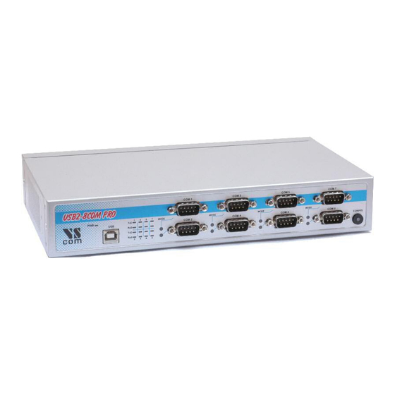
Page 9: Vscom Usb-8Com Pro
It is not difficult to find the appropriate part in any other language version of Windows. The current version of the driver is 2.04.16, the version of the firmware in VScom USB-COM PRO is 1.0.0. Usually any hardware configuration is described before the software, including drivers. However the configuration of VScom USB-COM PRO requires the serial port drivers installed, so these are... -
Page 10: The Drivers For Windows 10
CD-ROM, in the top folder. Just log on to Windows with Administrator privileges, and start the program. It is a self-extracting archive, which in turn executes the included installation software. The installation is a text-mode Console Application, which pretty much looks like a DOS box (see figure 6). June 2009 USB-COM PRO User Manual... -
Page 11: Check Installation Of The Drivers
3.1.2 Uninstall Drivers from Pre-Installation Executable First disconnect all USB-COM from your system. Then open “Control Panel”, and in that start the “Add or Remove Programs” applet. The FTDI CDM Driver Package appears twice in the list June 2009 USB-COM PRO User Manual... -
Page 12: Install Drivers The Classical Way
COM PRO to a free USB port of your computer. Windows will detect the new hardware, and identify it as an unknown type. Of course “unknown” only if this is the first time drivers are installed to the system. The second USB-COM PRO is recognized automatically, without further interaction. -
Page 13: Help The Wizard
CD-ROM, the automatic option uses a long time to search. So instead select the “(Advanced)” option, and click on Next. Figure 10: Select appropriate driver Guide Windows to the directory where you saved the latest version or to the CD-ROM, and again click on Next. June 2009 USB-COM PRO User Manual... -
Page 14: Check Installation Of The Drivers
Open the Device Manager. In the Device Manager open the device class of “Ports (COM & LPT)” In this class you’ll see all the entries of “USB Serial Port”. Now open the properties of the serial port to configure. “Anschlüsse (COM und LPT)” in einem deutschen Windows June 2009 USB-COM PRO User Manual... -
Page 15: Usb Serial Port Properties
3 The Drivers for Windows Figure 12: USB Serial Port Properties Click on the button named “Advanced...” to see the special configuration options. They are available via panel 13. June 2009 USB-COM PRO User Manual... -
Page 16: Rename The Serial Port
When either of the criteria becomes true, the data is sent to the Host PC. Then the application software will recognize the received data. If a small amount of data is received, or the June 2009 USB-COM PRO User Manual... -
Page 17: Serial Enumerator
RTS for correct operation. Otherwise there may be error messages when the port is opened again to use the device. Enabling this option causes the RTS to stay active even when the application closes the serial port. June 2009 USB-COM PRO User Manual... -
Page 18: Disable Modem Ctrl At Startup
However it requires nearly the same millisecond to send one byte or more. So if the application sends complete buffers instead byte-by-byte, the driver can send more than one byte per millisecond. This way the USB serial port is permanently fed with work to send. June 2009 USB-COM PRO User Manual... -
Page 19: Hardware Configuration
first (or only) serial port is disconnected from the external devices. On your USB-COM PRO press the button named “Config” for at least 3 seconds, a LED in the button will light in blue color. The USB-COM PRO is in configuration mode now. Then start the UsbComCfg program, it searches and detects all USB-COM PRO in configuration mode. -
Page 20: Usbcomcfg Started
The button to “Commit Changes” transfers the required parameters to the selected device. They are stored in non-volatile RAM, and activated after that. The device remains in Configuration mode. June 2009 USB-COM PRO User Manual... -
Page 21: Usbcomcfg Multi-Port Selection
You may select several ports of one device at the same time. This is done by the usual Windows method, i.e. clicking with Shift- or Ctrl-Key pressed. The selected configuration then applies to all selected ports, “Commit Changes” configures all of them at the same time. June 2009 USB-COM PRO User Manual... -
Page 22: Configuration Via Terminal Program
Watching the LEDs on each device you can see how the configuration proceeds from device to device. When all USB-COM PRO are configured, they are still in Configuration mode, shown by the blue LED. Shortly press the “Config” button put the devices back to normal operation. The LED in the button will go dark. -
Page 23: Exit The Configuration (0)
Line Feed character to each line. So you’ll see the text quickly scroll in your Windows. This is intentional, the Configuration mode redraws the screen, so you have a chance to change the parameters of your terminal application. The line lists the USB-COM PRO found using this serial port. -
Page 24: Show Port Configurations (1)
3 Selects all serial ports at once. This number changes depending on the number of available serial ports. For this example port 1 is selected for configuration. To get details about the available modes please read section 2.2. June 2009 USB-COM PRO User Manual... -
Page 25: Default Port Configuration (3)
4.2.6 Show Configuration File (5) Configuring each serial port (and each option of it) in a USB-COM PRO can become a long process. And this has to be repeated on the next device, and so on. To make the handling much easier the current configuration can be changed to a file, for later usage. -
Page 26: Upload Configuration File (6)
When the Terminal Emulation software allows to save the configuration of the device, it will also allow to send a text file to the USB-COM PRO. This way a previously saved configuration can be loaded to the USB-COM PRO. It can also be loaded to another device, for ease of configuring a series of USB-COM PRO. -
Page 27: Technical Background On Rs485
(one million divided by the bit rate) Bitrate in meters, you should consider Termination Resistors. with an optional resistor Assuming group speed of 100.000km/s, 10 travels to damp out, and 10% of bit time June 2009 USB-COM PRO User Manual... -
Page 28: Polarization
All devices appear the same on the cable, they have the same function. There is no Master or Slave defined by the hardware. Such functions are implemented by way of the data transmission protocol. Also RS485 addresses are defined by that protocol, as well as bus access. June 2009 USB-COM PRO User Manual... -
Page 29: 4-Wire Scheme
RS422 requires dedicated wire pairs for transmit and receive. The transmit wires are used to send data to as many as 10 receivers, as stated in the specifications of RS422. Since the VScom products use RS485 line driver technology, up to 32 receivers are possible. -
Page 30: Connector Definitions
6 Connector Definitions 6 Connector Definitions All the VScom USB-COM devices provide the today standard DB9 male connector for the signals of the serial ports. Some models may offer a DB25 male connector for RS232, other may provide an additional Terminal block for RS422 and RS485 signals. -
Page 31: Db25 Male Rs 232
6 Connector Definitions 6.2 DB25 male RS 232 This connector is only available on the VScom USB-COM 25 model. The pins not mentioned are a no-connect. RS232 RS232 Table 8: DB25 male RS232 Figure 27: DB25 male RS232 6.3 Terminal Block The Terminal Block connector is designed for connecting RS422 or RS485 signals.
Need help?
Do you have a question about the USB-COM PRO and is the answer not in the manual?
Questions and answers