Table of Contents
Advertisement
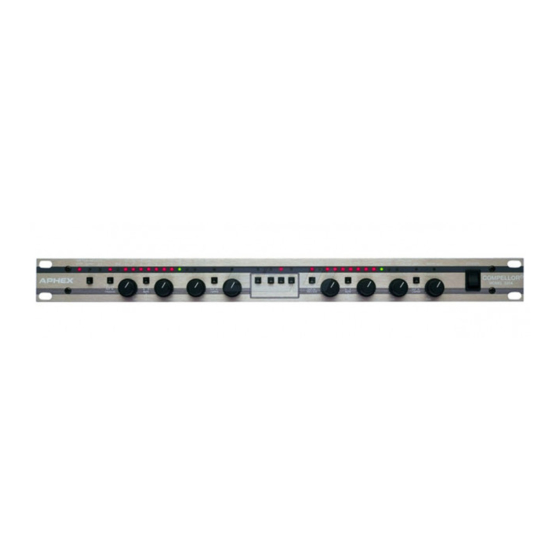
320A
Compellor
Compellor
®
®
Owner's Manual
Dual Mono/Stereo Automatic Level Controller
Manual P/N 999-0760 • Revision 2 • 09/30/03
Copyright 2003 Aphex Systems Ltd. All rights reserved. Printed in U.S.A. Written and produced by Donn Werrbach.
S Y S T E M S
11068 Randall St., Sun Valley, CA 91352 U.S.A.
Advertisement
Table of Contents

Summary of Contents for Aphex Compellor 320A
- Page 1 Dual Mono/Stereo Automatic Level Controller Manual P/N 999-0760 • Revision 2 • 09/30/03 Copyright 2003 Aphex Systems Ltd. All rights reserved. Printed in U.S.A. Written and produced by Donn Werrbach. S Y S T E M S 11068 Randall St., Sun Valley, CA 91352 U.S.A.
-
Page 2: Table Of Contents
Safety Declarations For protection against electric shock, do not remove the cover. No user serviceable parts inside. CAUTION: WARNING: This equipment has been tested and found to comply with the limits for a Class A digital device pursuant to Part 15 of the FCC Rules. These limits are designed to provide reasonable protection against harmful interference when the equipment is operated in a commercial environment. -
Page 3: Contents
320A Compellor 2. Quick Start - Page 6 3. Introduction - Page 7 4. Installation - Page 10 5. Specifications - Page 14 3.1 What Is A Compellor? 3.2 What Does It Do? 3.3 How Does It Work? 3.4 A BIt Of Compellor History 4.1 Unpacking... - Page 4 320A Compellor 6. Operation - Page16 6.1 Introduction 6.2 Recording 6.3 Mixing 6.4 Mastering 6.5 VIdeo Post Production 6.6 Sound Reinforcement 6.7 Live Concerts 6.8 Broadcast Radio Pre-processing 6.9 Broadcast STL/Phone Line Driver 6.10 Television Broadcasting and Cable Systems 6.11 Video and Audio Tape Duplication 6.12 Voice Processing...
- Page 5 Page 5...
-
Page 6: Quick Start
320A 2. Quick Start Compellor You can use this quick setup to get a signal through your Compellor right away. Then. you’ll want to go on and read through the manual to discover the wealth of information that is available to you. -
Page 7: Introduction
3. Introduction 3.1 What Is A Compellor? A Compellor is the first and only product designed specifically for the transparent control of audio levels. While other audio processors are designed simply to compress and limit audio signals, a Compellor is designed to intelligently manage the dynamic range of audio without causing noticeable changes to the character and feeling of the sound. - Page 8 Jon Sanserino visited Honolulu and auditioned Werrbach’s prototype at the Audissey record- ing studio where he was intrigued by its possibilities. Finally, in 1983, an agreement was reached between Werrbach and Marvin Caesar, the president of Aphex Systems, to produce the Compellor as a product line.
- Page 9 In 1994, Aphex introduced the current Compellor Models 320A and 323A. The model “A” revision signifies the inclusion of an improved patented Leveler circuit called the “Frequency Discriminate Leveler” (FDL) while all other aspects of the Model 320 remain the same. With the FDL, Compellors became even more transparent and useful than ever before.
-
Page 10: Installation
320A Compellor 4.1 Unpacking Your Compellor was packed carefully at the factory in a container designed to protect the unit during shipment. Nevertheless, Aphex recommends making a careful inspection of the ship- ping carton and the contents for any signs of physical damage. -
Page 11: Power Cord
4.4 Power Cord The Compellor uses a standard IEC power cord set. The appropriate mains plug for each country is normally shipped with each unit. However, if you must install or replace the plug, Power Cord Color Codes USA Color Code IEC/Continental Color Code Black = Hot (live) Brown = Hot (live) -
Page 12: Remote Connector
4.10 Remote Connector Remote control, a feature of the Models 320A and 323A. 4.11 Reference Level Setting The Compellor should be normalized to match the operating level of your system. When the Compellor is properly matched to the system reference level, then the Compellor’s meters... - Page 13 The output impedance of 65 ohms is optimized for driving long cables and consequently l l e Unique servo balanced output circuitry automatically maintains the proper gain and level into a balanced or unbalanced output line. Output connections are made by means of 3-pin male XLR jacks. The pinout follows the same conventions as the input jacks described above, and you should exercise the same care about wiring as described for input wiring.
-
Page 14: Speci Cations
320A Compellor 5.1 INPUTS Connector: Type: Impedance: Operating Level: Max input level: CMRR: 5.2 OUTPUTS Connector: Type: Impedance: Max level out (bal): Max level out (unbal): 5.3 AUDIO Frequency response: Hum & noise: No gain reduction: 10dB gain reduction: Crosstalk @ 20KHz:... -
Page 15: Ratio
5.6 RATIO Compressor: 1.1:1 to 3:1 program dependent Leveler: 20:1 Limiter: >30:1 5.7 ATTACK TIMES Compressor: 5 to 50mSec program dependent Leveler, fast: 20Hz = 1.5 Sec > 1KHz Frequency Discriminate Leveler Leveler, slow: 20Hz = 5 Sec > 1KHz Frequency Discriminate Leveler Limiter: 1 uSec 5.8 RELEASE TIMES... -
Page 16: Operation
320A 6. Operation Compellor 6.1 Introduction The “Quick Start” guide in the front of this manual is the best way to begin using your Compellor. You will get a good feel for what is going on, and you will have a signal going through the processor, ready for fine tuning. -
Page 17: Video Post Production
has too wide a dynamic range, it can cause broadcast processors (if the processing does not include the Compellor) to work too hard and generate audible artifacts. These are all reasons to master a final mix which has a controlled dynamic range. The goal, of course, is to maintain the sound quality of the studio while you are trying to ‘tighten’... -
Page 18: Broadcast Stl/Phone Line Driver
320A 6. Operation Compellor numerous other devices which effectively control the level differences, but none have the transparency of the Compellor. These other devices, particularly multiband compressors and limiters, have a ‘sweet spot’ which renders the best results. Adjust the Compellor so that its output is driving the downstream processors at their sweet spot. -
Page 19: Hard Disk Recording
6.13 Hard Disk Recording Transferring music to hard disk can be improved using a Model 320D. It is a known fact that CD’s are mastered at varying average levels with some strikingly lower or higher in volume level than others. When building a broadcast or webcast music library on a hard disk audio server, it would be nice to have a way to even out those levels so the on-air segues will always be smooth and fat. -
Page 20: System Description
320A 7. System Description Compellor 7.1 Signal Flow The Compellor contains an input stage, an intermediate VCA stage, and an output stage. The input audio signal undergoes all processing in the VCA stage and is subsequently sent out through the output stage. A side chain system produces the control signals which change the VCA gain according to the signal processing requirements. -
Page 21: Compressor Function
7.4 Compressor Function The compressor cooperates with the leveler to supply more consistent program level control than possible with the leveler alone. While the leveler is relatively slow responding, the com- pressor works much faster to control both the transients and other quick changes in the sound level. -
Page 22: Stereo Enhance
If the compression is stereo linked then the effects of “Stereo Enhance” are eliminated. 7.9 Stereo Linking Two link modes are possible with the model 320A. The first mode links only the leveling systems of the two channels. The second mode links both leveling and compression. You cannot link compression only. -
Page 23: Output Control
7.14 Output Control This control allows you to normalize the output level to 0VU after the processing is set up. It will usually get set around 12 o’clock, but there is a plus or minus 10dB range available which is useful if you need to match a slightly odd level. 7.15 Process Switch This operates a bypass relay which completely bypasses the Compellor in the process out mode. -
Page 24: Gain Reduction Metering
320A Compellor 7.19 Gain Reduction Metering When the Meter Select is toggled into “G.R.” the bi-color LED meter is programmed to indi- cate a bar graph from left to right but differing from the program level indications. In this case, the bar is entirely green except for a possible red dot which floats within the green bar. -
Page 25: Warranty & Service
Any and all warranties are limited to the duration of the warranty stated above. EXCLUSION OF CERTAIN DAMAGES Aphex Systems’ liability for any defective unit is limited to the repair or replacement of said unit, at our option, and shall not include damages of any other kind, whether incidental, consequential, or otherwise. -
Page 26: Appendix A: Balanced And Unbalanced Lines And Operating Levels
320A Compellor Appendix A: Balanced and Unbalanced Lines and Operating Levels Interfacing all types of equipment with balanced and unbalanced lines and can sometimes be trouble - some. First you have to somehow connect balanced to unbalanced and then you have to deal with dif - ferent levels. -
Page 27: Appendix B: Dealing With Grounds And Hum
320A Compellor is cancelled out by the di erential ampli er. Figure 1 illustrates how the hum is induced into both wires equally and therefore is cancelled out. Since the balanced line has wires that are twisted together, each wire tends to pick up the same amount of induction from external sources. - Page 28 320A Compellor There are basically three ways to attack the prob - lem of a ground loop. First is to eliminate it from its source, and the second is to re-route it through another path. The third is to balance out your unbal - anced audio interfaces.
- Page 29 Appendix C: Proper Wiring Techniques A true balanced line should be used wherever your equipment allows. Use “twisted pair” shielded cable. For unbalanced wiring you should use high grade, low capacitance shielded wire for best results. If you have an unbalanced output but have a balanced input, the “pseudo-balanced”...
- Page 30 320A Compellor TABLE 1 - BALANCED & UNBALANCED CONNECTOR WIRING STANDARDS 3-Pin XLR Pin-1 Pin-2 Pin-3 1/4” TS Phone Sleeve audio line from a low impedance and receive into a high impedance. Generally, a minimum 1: 10 ratio is possible. This is called “bridging”. This has become modern practice and all balanced inputs are normally running 10K ohms or higher impedance.
- Page 31 output circuit. We strongly recommend that you refer to your various equipment manuals to nd out what is used in each case before hooking up to unbalanced lines. When connecting a balanced output to a balanced input, however, you don’t need to know what kind of balanced output you are dealing with.
- Page 32 320A Compellor PART 2: BALANCED OUT to UNBALANCED IN It was mentioned that there are several types of balanced output stages in use today. The following diagrams show you how to properly unbalance each type of output. If you follow these instructions, you should have no problems.
- Page 33 PART 3: UNBALANCED to UNBALANCED Standard Cable (Guitar Cord) Mono (TS) Phone Plug PART 4: UNBALANCED OUT to BALANCED IN Standard Method Mono (TS) Phone Plug Stereo (TRS) Phone Plug (Guitar cord of Part 3 above usualy works just as well) Mono (TS) Phone Plug PART 5: “Y”...
-
Page 34: Analog Systems
320A Appendix E Compellor Appendix E: About Reference Levels ANALOG SYSTEMS Systems declaring the average reference level are very different than systems declaring the peak reference level. In the United States, most analog systems still use the VU meter and we declare the +4dBu (for example) reference level to be the average program level. - Page 35 In a world where all audio levels would be monitored by VU meters, this SMPTE standard would make things simple. Since VU meters measure something close to the average level, we could simply equate 0VU to -20dBFS with a calibration tone. We could mix and track on the VU meters, knowing there is 20dB of headroom in the digital domain for peaks.
- Page 36 320A Appendix F Compellor Appendix F Digital–vs–Analog; Peak–vs–RMS How To Deal With The Confusion By Donn Werrbach • 10/03/03 The Confusion The matter of audio level measurements and specifications can be very confusing at times. That is because some specs relate to peak measurements and some to average or RMS measurements.
- Page 37 room above the maximum PPM indication. By controlling the audio levels to maintain good PPM readings, there can be no possibility of the electronics clipping the audio. The disad- vantage is that to maintain a good average volume level, it takes very clever people riding the gain who can accurately guess at the crest factor of all the sounds.
- Page 38 320A Compellor Digital Audio’s Contributions to the Problem Death of a Perfectly Good VU Meter As superior as the VU monitor is for general audio work, it seems the fate of the VU paradigm is going to be a sad but quiet death from abandonment. Digital audio technocrats are dictating technology from their laboratories far away from where people create and produce art.
- Page 39 Most simply stated, the Compellor will accept an audio input, digital or analog, level it out and add some compression making it more consistent in average level. The resulting aver- age output level will target around 0VU. That means –20dBFS in the digital audio world and +4dBu (or –10dBV depending in the level reference settings) in the analog world.
- Page 40 320A Compellor outputs into the codec, the level will then shift and be louder with the analog input. That may give the effect of a fuller on-air sound when the coder is driven by analog because the on-air audio processor at the decoder side is driven with higher input level.
- Page 41 Page 41...
Need help?
Do you have a question about the Compellor 320A and is the answer not in the manual?
Questions and answers