Table of Contents
Advertisement
Advertisement
Table of Contents

Summary of Contents for Leuze lumiflex Scan
- Page 1 SCAN Measuring Light Curtain Connecting and Operating Instructions...
- Page 2 Notes on using these connecting and operating instructions These connecting and operating instructions contain information regarding the proper and effective use of SCAN light curtains. It is included in the scope of delivery. Safety notes and warnings are designated by the symbol Leuze lumiflex GmbH + Co.
-
Page 3: Table Of Contents
Standard Mounting ............11 Mounting SCAN with the Protective Mounting Profile ......12 Electrical Installation . -
Page 4: System Overview And Range Of Applications
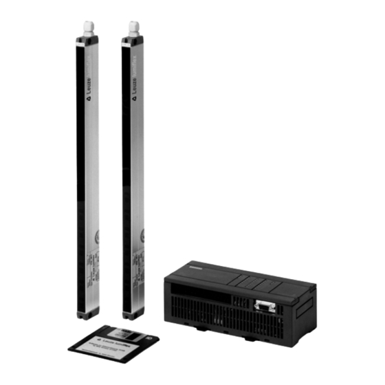
System Overview and Range of Applications System Overview SCAN light curtains consist of a transmitter and a receiver. Like a light barrier, they work with modulated infrared light and stand out due to the following features: • Measurement field up to 6 m wide, from 900 to 3000 mm high •... -
Page 5: Range Of Applications
Range of Applications The scope of SCAN applications ranges from simple detection or measuring tasks, such as controlling projection or the presence of an object, to contour or shape recognition. Overhang control Customer machine Measuring of widths control Loop control... -
Page 6: Safety Notes
SCAN to be connected directly to the Siemens S7-200. Drivers for controls from other manufacturers can be produced upon request. Figure 3 shows the system configuration of SCAN in both its standard design and its master/slave version. -
Page 7: Function
“light path interrupted”) is output either as an aggregate signal at the switch output or as a single measurement value within a serial data stream via the RS 485 interface of the receiver. Display Elements SCAN SCAN transmitter receiver Vor Anschluss Vor Anschluß... -
Page 8: Rs 485 Data Interface
The signal statuses of the individual light axes (“light path unobstructed” or “light path interrupted”) are transmitted as a serial data stream over the RS 485 interface. The transmission takes place in half duplex mode at 19.200 baud in the Leuze lumiflex- specific protocol described below. -
Page 9: Driver Program For The Plc Control (E.g. Siemens S7-200)
The individual light axis are made available to the user bit-by-bit beginning at memory position VB20 (1 = light, 0 = no light), continuing from the first light axis (at the SCAN connection) to the last light axis (at SCAN´s free end). -
Page 10: Contamination And Error Signal Output
This pnp output normally carries +24V DC. In case of a weak receiver signal caused by contamination or misalignment, or in case of a fault, this output is switched to high resistance. The output is short-circuit-proof and can carry up to 70 mA. SCAN... -
Page 11: Mounting
Mounting Standard Mounting SCAN units are mounted by means of through holes in the profile end pieces. (For the distance between holes, see the dimensional table on page 17 and the dimensional drawing on page 18.) The holes have a diameter of 5.3 mm. -
Page 12: Mounting Scan With The Protective Mounting Profile
Mounting SCAN with the Protective Mounting Profile To provide additional mechanical protection, the SCAN can be snapped into a protective mounting profile. This is recommended for larger measurement heights and when the units need to be adjustable. The protective mounting profile can be used with either a standard mounting bracket or a swivelling mounting support with vibration damping.. -
Page 13: Electrical Installation
(see Accesso- ries). The shield must be connected to PE. The cables must be laid separately from mains power cables. The following tables show the terminal assignments of the transmitter and receiver. SCAN Transmitter SCAN Receiver Wire color Meaning Wire color... - Page 14 +24V DC PLC input green at 0V Fig. 7: SCAN as a Switching Light Curtain in Stand-alone Operation 5.2.2 SCAN as a Measuring Light Curtain with the Siemens S7-200 RS485 SCAN transmitter pink (RS 485 +) at PLC-RS 485, SCAN receiver...
-
Page 15: Start-Up
33 - 250 (6 light axes per 150 mm measurement height) µ Time required per light axis Transmitter Light-emitting diodes as defined by EN 60825-1: 1994 + A1:2002 + A2:2001 Class Wave length 880 nm Pulse duration 7 ms Pulse pause 3,12 ms 8,73 µW Output SCAN... - Page 16 Humidity 15 ... 95 % (non-condensing) Storage temperature -25 ... +75 °C *) other measurement heights up to 3000 mm upon request Dimensions, Weights and Scanning Times of the SCAN light curtains Device Type Protecting Dim. B Mounting Dim. Weight Time/Scan height = Dim.A...
- Page 17 SCAN Mounting dimension Clearance for removing the plug Screw M5 or M5 End of sensing zone Fig. 9: Dimensional Drawing of SCAN Series S30 SCAN...
- Page 18 Mounting dimension End of sensing zone Coupling Total length including coupling, max. 250 mm Fig. 10: Dimensional Drawing of SCAN “Cascaded Design“ SCAN...
-
Page 19: Selection And Ordering Information
R = receiver Resolution [mm] dddd Measurement height [mm] Only for cascadable units M = master unit S = slave unit Order Numbers and Accessories The scope of supply of a SCAN consists of: • 1 SCAN transmitter ST... SCAN... - Page 20 The snap-open profile offers additional protection and variable possibilities for moun- ting using either a standard mounting bracket or a swivelling mounting support. 30,65 SCAN protective mounting profile SCAN Fig. 11: Dimensional Drawing of “SCAN Protective Mounting Profile“ For the dimensions of B, see dimensional table on page 17/18. SCAN...
- Page 21 1 cable from the transmitter to the control cabinet and 1 cable from the receiver to the control cabinet Other heights upon request Only for use with the SCAN protective mounting profile 2 pieces each required for the transmitter and the receiver SCAN...
-
Page 22: Declaration Of Confirmity
Declaration of Confirmity SCAN...
Need help?
Do you have a question about the Scan and is the answer not in the manual?
Questions and answers