Table of Contents
Advertisement
Quick Links
CD RDS RECEIVER
DEH-P6000UB
This service manual should be used together with the following manual(s):
Model No.
Order No.
CX-3240
CRT4050
For details, refer to "Important Check Points for Good Servicing".
PIONEER CORPORATION
PIONEER ELECTRONICS (USA) INC. P.O. Box 1760, Long Beach, CA 90801-1760, U.S.A.
PIONEER EUROPE NV Haven 1087, Keetberglaan 1, 9120 Melsele, Belgium
PIONEER ELECTRONICS ASIACENTRE PTE. LTD. 253 Alexandra Road, #04-01, Singapore 159936
PIONEER CORPORATION 2007
Mech.Module
S10.5COMP2-iPod/USB
CD Mech. Module : Circuit Descriptions, Mech. Descriptions, Disassembly
4-1, Meguro 1-chome, Meguro-ku, Tokyo 153-8654, Japan
DEH-P6000UB/XN/EW5
Remarks
ORDER NO.
CRT4036
/XN/EW5
K-ZZW. OCT. 2007 Printed in Japan
Advertisement
Table of Contents

Related Manuals for Pioneer CX-3240


Summary of Contents for Pioneer CX-3240
- Page 1 PIONEER CORPORATION 4-1, Meguro 1-chome, Meguro-ku, Tokyo 153-8654, Japan PIONEER ELECTRONICS (USA) INC. P.O. Box 1760, Long Beach, CA 90801-1760, U.S.A. PIONEER EUROPE NV Haven 1087, Keetberglaan 1, 9120 Melsele, Belgium PIONEER ELECTRONICS ASIACENTRE PTE. LTD. 253 Alexandra Road, #04-01, Singapore 159936 PIONEER CORPORATION 2007 K-ZZW.
-
Page 2: Safety Information
SAFETY INFORMATION CAUTION This service manual is intended for qualified service technicians; it is not meant for the casual do-it-yourselfe. Qualified technicians have the necessary test equipment and tools, and have been trained to properly and safely repair complex products such as those covered by this manual. Improperly performed repairs can adversely affect the safety and reliability of the product and may void the warranty. - Page 3 CAUTION Danger of explosion if battery is incorrectly replaced. Replaced only with the same or equivalent type recommended by the manufacture. Discord used batteries according to the manufacture's instructions. DEH-P6000UB/XN/EW5...
- Page 4 [Important Check Points for Good Servicing] In this manual, procedures that must be performed during repairs are marked with the below symbol. Please be sure to confirm and follow these procedures. 1. Product safety Please conform to product regulations (such as safety and radiation regulations), and maintain a safe servicing environment by following the safety instructions described in this manual.
-
Page 5: Table Of Contents
CONTENTS SAFETY INFORMATION .............................2 1. SERVICE PRECAUTIONS..........................6 1.1 SERVICE PRECAUTIONS .........................6 1.2 NOTES ON SOLDERING...........................6 2. SPECIFICATIONS.............................7 2.1 SPECIFICATIONS ............................7 2.2 DISC/CONTENT FORMAT.........................8 2.3 PANEL FACILITIES ............................9 2.4 CONNECTION DIAGRAM........................12 3. BASIC ITEMS FOR SERVICE ........................13 3.1 CHECK POINTS AFTER SERVICING .....................13 3.2 PCB LOCATION ............................13 3.3 JIGS LIST ..............................14 4. -
Page 6: Service Precautions
1. SERVICE PRECAUTIONS 1.1 SERVICE PRECAUTIONS 1. You should conform to the regulations governing the product (safety, radio and noise, and other regulations), and should keep the safety during servicing by following the safety instructions described in this manual. 2. Before disassembling the unit, be sure to turn off the power. -
Page 7: Specifications
2. SPECIFICATIONS 2.1 SPECIFICATIONS DEH-P6000UB/XN/EW5... -
Page 8: Disc/Content Format
2.2 DISC/CONTENT FORMAT DEH-P6000UB/XN/EW5... -
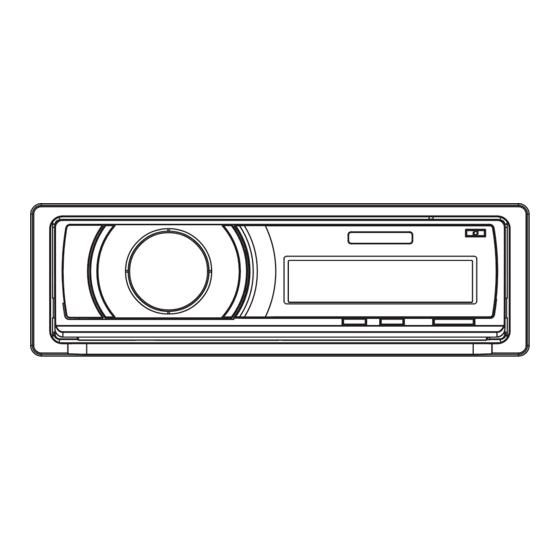
Page 9: Panel Facilities
2.3 PANEL FACILITIES DEH-P6000UB/XN/EW5... - Page 10 DEH-P6000UB/XN/EW5...
- Page 11 Fixing the front panel If you do not operate the removing and attaching the front panel function, use the supplied fixing screws and holders to fix the front panel to this unit. 1. Attach the holders to both sides of the front panel. Holder Holder CND1249...
-
Page 12: Connection Diagram
2.4 CONNECTION DIAGRAM DEH-P6000UB/XN/EW5... -
Page 13: Basic Items For Service
3. BASIC ITEMS FOR SERVICE 3.1 CHECK POINTS AFTER SERVICING To keep the product quality after servicing, please confirm following check points. r i f Confirm whether the customer complain has The customer complain must not be been solved. reappeared. If the customer complain occurs with the Display, audio and operations must be specific media, use it for the operation check. -
Page 14: Jigs List
3.3 JIGS LIST - Jigs List Name Name Jig No. Jig No. Remarks Remarks Test Disc TCD-782 Checking the grating L.P.F. Checking the grating (Two pieces) - Grease List Name Name Grease No. Grease No. Remarks Remarks Grease GEM1024 CD Mechanism Module Grease GEM1045 CD Mechanism Module... - Page 15 DEH-P6000UB/XN/EW5...
-
Page 16: Block Diagram
4. BLOCK DIAGRAM TUNER AMP UNIT 10 9 8 18 19 20 21 FM/AM TUNER UNIT IC 5 IC 3 EEPROM 5V t 3.3V 5.0V ANTENNA ANT401 AM ANT FMRF IC 2 2.5V IC 1 FM ANT 3.3V FMRF MIXER, IF AMP DET, FM MPX, RDS DECODER RF adj... -
Page 17: Panel Unit
CN301 MUTE BZ601 BUZZER Q303 PEE 24 RCA OUT TUNPCE2 TUNPCE1 TUNPDI TUNPDI TUNPDO TUNPDO X601 TUNPCK Q302 TUNPCK 15.00MHz VDD REGULATOR XOUT LDET LDET Q901 SYSTEM Q902 CONTROLLER IC 601(1/2) Q401 PEG402A8 RDSDATA DALMON RDSSDT RDSHSLK RDS57K CN981 B SENS Q402 BSENS B.UP... - Page 18 - FM/AM Tuner Unit 10 9 8 18 19 20 21 IC 5 IC 3 EEPROM 5V t 3.3V 5.0V AM ANT FMRF AT T IC 2 2.5V IC 1 FM ANT 3.3V AT T FMRF MIXER, IF AM P DET, FM MPX, RDS DECODER RF adj...
-
Page 19: Diagnosis
5. DIAGNOSIS 5.1 OPERATIONAL FLOWCHART Power ON Vcc = 5 V Pin14 BSENS Pin16 BSENS = L ASENS Pin73 ASENS = L DSENS Pin9 DSENS = L ASENBO<-H Pin38 CSENS - 2 V < CSENS < 3 V Pin91 Last source returns. CD loading functions are available. -
Page 20: Error Code List
5.2 ERROR CODE LIST - CD Error Messages If a CD is not operative or stopped during operation due to an error, the error mode is turned on and cause(s) of the error is indicated with a corresponding number. This arrangement is intended at reducing nonsense calls from the users and also for facilitating trouble analysis and repair work in servicing. - Page 21 iPod error Message Cause Action NO SONGS No songs in the iPod Transfer the songs to the iPod. Select a list that contains the songs. STOP No songs in the current list Disconnect the cable from the iPod. Once the iPod main menu is displayed, connect the cable again.
-
Page 22: Connector Function Description
5.3 CONNECTOR FUNCTION DESCRIPTION 1. BUS+ 2. GND IP-BUS INPUT 3. GND 4. NC 5. BUS- 6. GND 7. BUS L+ 8. ASENB 9. BUS R+ SUBWOOFER FRONT 10. BUS R- OUTPUT OUTPUT 11. BUS L- AUX IN AUX IN ANTENNA WIRED REMOTE INPUT 1 3 5 7 9 11 13 15... -
Page 23: Service Mode
6. SERVICE MODE 6.1 CD TEST MODE During pressing the "SOURCE" and "RPT" keys simultaneously, perform the reset-start, then turn ON the CD to enter the CDS test mode. • How to issue the 1 - 6 keys in the 08 model's slave test: The specification of the 08 model does not include the 1 - 6 keys issuance function for H/U and the remote control unit. - Page 24 - Flow Chart [Key] [SOURCE] + [RPT] + BU + ACC Contents Test Mode In Display [CD] or [SOURCE] Source On [BAND] Power On Power On RF AMP SPINDLE (T.Offset is adjusted) (T.Offset is not adjusted) Gain switching Speed switching 00 00 00 99 99 99 [BAND]...
-
Page 25: Disassembly
7. DISASSEMBLY *NOTE) While the photograph shown is slightly different from this model in shape, the disassembly procedure is the same. Removing the Keyboard Unit (Fig.1,2,3) Pull arrow direction and remove Detach Grille Assy.(Fig.1) Fig.1 Remove the Knob Unit.(Fig.2) Detach Grille Assy Knob Unit Fig.2 Remove the four screws.(Fig.3) - Page 26 Removing the CD Mechanism Module (Fig.6) Remove the four screws. Disconnect the cable and then remove the CD Mechanism Module. Fig.6 CD Mechanism Module Removing the Panel AssyFig.7,8) Remove the two screws.(Fig.7) Fig.7 Panel Assy Push the place of the arrows and then remove Panel Assy.(Fig.7,8) Fig.8 Removing the Panel Unit(Fig.9,10)
- Page 27 Removing the Tuner amp Unit(Fig.11,12) Remove the three screws.(Fig.11) Remove the two screws.(Fig.11) Fig.11 Tuner amp Unit Straighten the tabs at four locations indicated.(Fig.12) Remove the screw and then remove the Tuner amp Unit.(Fig.12) Fig.12 DEH-P6000UB/XN/EW5...
- Page 28 - How to hold the Mechanism Unit 1. Hold the Upper and Lower Frames. 2. Do not hold the front portion of the Upper Frame, because it is not very solid. Do not squeeze this area. - Removing the Upper and Lower Frames 1.
- Page 29 - How to remove the CD Core Unit 1. Apply Shorting Solder to the flexible cable of the Pickup, and disconnect it from the Shorting Solder connector. 2. Unsolder the four leads, and loosen the Screw. 3. Remove the CD Core Unit. Caution: When assembling the CD Core Unit, assemble it with the SW in a clamped state so as not to damage it.
-
Page 30: Each Setting And Adjustment
8. EACH SETTING AND ADJUSTMENT 8.1 CD ADJUSTMENT 1) Cautions on adjustments 2) Test mode In this product the single voltage (3.3 V) is used for the This mode is used to adjust the CD mechanism module. regulator. The reference voltage is the REFO1 (1.65 V) To enter the test mode. -
Page 31: Checking The Grating After Changing The Pickup Unit
8.2 CHECKING THE GRATING AFTER CHANGING THE PICKUP UNIT Note : The grating angle of the PU unit cannot be adjusted after the PU unit is changed. The PU unit in the CD mechanism module is adjusted on the production line to match the CD mechanism module and is thus the best adjusted PU unit for the CD mechanism module. - Page 32 Grating waveform Ech -> Xch 20 mV/div, AC Fch -> Ych 20 mV/div, AC 0 degrees 30 degrees 45 degrees 60 degrees 75 degrees 90 degrees DEH-P6000UB/XN/EW5...
-
Page 33: Pcl Output Confirmation
8.3 PCL OUTPUT CONFIRMATION - PCL output In the normal operation mode (with the detachable panel installed, the ACC switched ON, the standby mode cancelled), shift the TESTIN IC601(Pin 61) terminal to H. The clock signal is output from the PCL terminal IC601(Pin 37). The frequency of the clock signal is 468 750 Hz that is one 32th of the fundamental frequency. -
Page 34: Exploded Views And Parts List
9. EXPLODED VIEWS AND PARTS LIST OTES : Parts marked by " * " are generally unavailable because they are not in our Master Spare Parts List. The > mark found on some component parts indicates the importance of the safety factor of the part. Therefore, when replacing, be sure to use parts of identical designation. - Page 35 PACKING SECTION PARTS LIST Mark No. Description Part No. Mark No. Description Part No. Polyethylene Bag CEG1160 Cord Assy CDP1040 Holder(L) CND1249 ••••• Holder(R) CND1250 Polyethylene Bag CEG1227 Handle CND3707 Battery CEX1065 Bush CNV3930 Remote Control Assy CXC8885 Protector XHP7016 Unit Box QHG3001 Protector...
-
Page 36: Exterior(1)
9.2 EXTERIOR(1) DEH-P6000UB/XN/EW5... - Page 37 EXTERIOR(1) SECTION PARTS LIST Mark No. Description Part No. Screw BSZ26P060FTC Screw BSZ30P060FTC Screw BSZ30P200FTC Cord Assy CDE8351 Earth Plate CNC8915 Cushion CNM8890 CD Mechanism Module(S10.5) CXK5770 Cable QDE3001 Tuner Amp Unit QWM3010 Screw BPZ26P070FTC Screw BSZ26P060FTC Screw BSZ26P200FTC > Fuse(10 A) YEK5001 Plug(CN981)
-
Page 38: Exterior(2)
9.3 EXTERIOR(2) DEH-P6000UB/XN/EW5... - Page 39 EXTERIOR(2) SECTION PARTS LIST Mark No. Description Part No. Mark No. Description Part No. Cord Assy XDP7003 Screw BMZ30P040FTB Holder CND3598 Case YNB5014 Remote Control Assy CXC8885 IC(IC1901) GP1UX51RK Cover CNS7068 Sub Panel Assy QXA3025 Panel QNS3004 Detach Grille Assy QXA3001 Screw BPZ20P080FTB...
-
Page 40: Cd Mechanism Module
9.4 CD MECHANISM MODULE 43 10 (1) : GEM1024 : GEM1045 DEH-P6000UB/XN/EW5... - Page 41 CD MECHANISM MODULE SECTION PARTS LIST Mark No. Description Part No. Mark No. Description Part No. CNV7805 CD Core Unit(S10.5COMP2-iPod) CWX3526 Rack CNV8342 Connector(CN101) CKS4182 Connector(CN701) CKS4186 Roller CNV8343 Screw BMZ20P025FTC Holder CNV8344 Screw BSZ20P040FTC CNV8345 Guide CNV9498 Screw(M2 x 3) CBA1511 CNV8348 Screw(M2 x 4)
-
Page 42: Schematic Diagram
10. SCHEMATIC DIAGRAM 10.1 OVERALL CONNECTION DIAGRAM(GUIDE PAGE) Note: When ordering service parts, be sure to refer to " EXPLODED VIEWS AND PARTS LIST" or "ELECTRICAL PARTS LIST". Large size SCH diagram : The power supply is shown with the marked box. FM : -20dBs AM : -20dBs IP-BUS : 2.2dBs... - Page 43 TUNER AMP UNIT R205 R206 R207 R208 R209 R210 FM : -0.9dBs AM : -0.9dBs CD : 10.1dBs 8.4V AUX : 9.3dBs IP-BUS : 9.3dBs AGND1 E.VOL CAPTAIN 6 L202 C303 R303 L201 4R7/35 R309 4R7K FRONT CN301 R310 RCA OUT C304 R304 4R7K...
- Page 44 DEH-P6000UB/XN/EW5...
- Page 45 DEH-P6000UB/XN/EW5...
- Page 46 DEH-P6000UB/XN/EW5...
- Page 47 CN701 A-a C DEH-P6000UB/XN/EW5...
-
Page 48: Keyboard Unit
10.2 KEYBOARD UNIT 5.1 V CN1901 OELG OELG R1901 DPDT 2R2K R1902 KYDT 2R2K DGND CN1951 OEL+B 14 V L1901 OEL+B ILB+ ILM+ CSENS SW+5 SWVDD ILMG ILMG ILMG JOYST(V) ILMG OELG DGND over~under A(UP) 0.00 0.50 9.0 V B(LEFT) 0.50 1.30 C(DOWN) - Page 49 KEYBOARD UNIT KYDT DPDT X1901 IC1901 CSS1577 GP1UX51RK 10.0MHz RESET R1935 R1937 DGND DGND JOYST(V) over~under 0.00 0.50 0.50 1.30 PUSH 1.30 2.30 2.30 3.70 Q1902 3.70 4.50 2SC4081 4.50 5.00 R1934 R1940 TI CONTROL S1906 3R9K CSX1120 OELG DGND R1953 Phase_A Enc_Com...
-
Page 50: Cd Mechanism Module(Guide Page)
10.3 CD MECHANISM MODULE(GUIDE PAGE) PICKUP UNIT(P10.5)(SERVICE) SWITCHES: CD CORE UNIT S901:HOME SWITCH..ON-OFF S903:DSCSNS SWITCH..ON-OFF S904:12EJ SWITCH....ON-OFF S905:8EJ SWITCH....ON-OFF The underlined indicates the switch position. M1 CXC7134 SPINDLE MOTOR M2 CXC4026 LOADING/CARRIAGE MOTOR CD DRIVER DEH-P6000UB/XN/EW5... - Page 51 CD CORE UNIT(S10.5COMP2-iPod) SIGNAL LINE FOCUS SERVO LINE TRACKING SERVO LINE CARRIAGE SERVO LINE SPINDLE SERVO LINE DEH-P6000UB/XN/EW5...
- Page 52 DEH-P6000UB/XN/EW5...
- Page 53 CN701 DEH-P6000UB/XN/EW5...
- Page 54 DEH-P6000UB/XN/EW5...
- Page 55 DEH-P6000UB/XN/EW5...
-
Page 56: Waveforms
10.4 WAVEFORMS - CD CORE UNIT Note : 1. The encircled numbers denote measuring points in the circuit diagram. 2. Reference voltage REFO1(1.65 V) 1DSCSNS 1DSCSNS 1DSCSNS 5 V/div 500 ms/div 5 V/div 500 ms/div 5 V/div 500 ms/div 28SNS 5CLCONT 28SNS 5 V/div... - Page 57 %RFAGC %RFAGC %RFAGC 1 V/div s/div 1 V/div s/div 1 V/div 2 ms/div µ µ 500 mV/div 500 mV/div 500 mV/div 9TIN 9TIN 9TIN 500 mV/div 500 mV/div 500 mV/div 4 Tracks Jump waveform 10 Tracks Jump waveform 32 Tracks Jump waveform Ref.: Ref.: Ref.:...
- Page 58 )CPRDY )CPRDY 2 V/div 50 ms/div 2 V/div 10 s/div 2 V/div ⁄SDA ⁄SDA 2 V/div 2 V/div 2 V/div ¤SCL ¤SCL 2 V/div 2 V/div ACC OFF with USB(iPod) device connecting. iPod Authentication Operation iPod Authentication Operation(zoom until 2 s) DEH-P6000UB/XN/EW5...
- Page 59 DEH-P6000UB/XN/EW5...
-
Page 60: Pcb Connection Diagram
11. PCB CONNECTION DIAGRAM 11.1 TUNER AMP UNIT NOTE FOR PCB DIAGRAMS TUNER AMP UNIT 1.The parts mounted on this PCB include all necessary parts for several destination. For further information for respective destinations, be sure to check with the schematic dia- CORD ASSY WIRE REMOTE INPUT gram. - Page 61 SIDE A IC351 CN301 C308 Q301 R314 R308 R317 R302 R305 ANTENNA C307 ANT401 R313 C305 C363 C304 C303 IC261 R262 C301 C306 D981 C362 C262 D982 L151 C302 D351 C215 R381 Y401 C154 C155 Q381 D352 R162 R161 C410 C217 C214 R360...
- Page 62 TUNER AMP UNIT > FU 301 (B,127,135) Fuse 3 A CEK1286 C361 C359 C313 FU301 R318 R316 C357 R321 C364 C312 C311 R322 R310 Q303 Q302 C310 R304 C353 C360 R311 R319 R312 C356 R320 C355 C358 R309 R357 R356 C352 R306 R355...
- Page 63 SIDE B C359 C365 C160 C161 C103 R115 R113 R104 R105 R114 R106 C151 R111 C914 C982 R109 R110 C921 R108 R107 R927 Q101 R112 C912 R925 R923 R924 Q921 R926 R921 R208 C216 C219 R393 R922 C213 C223 C221 R392 R210 Q391...
-
Page 64: Keyboard Unit
11.2 KEYBOARD UNIT KEYBOARD UNIT SIDE A D1904 C1905 DEH-P6000UB/XN/EW5... - Page 65 KEYBOARD UNIT SIDE B CN1951 C1912 C1915 R1933 TH1901 R1907 R1912 R1911 R1906 R1909 R1904 DEH-P6000UB/XN/EW5...
-
Page 66: Cd Core Unit(S10.5Comp2-Ipod)
11.3 CD CORE UNIT(S10.5COMP2-iPod) CD CORE UNIT(S10.5COMP2-iPod) SIDE A PICKUP UNIT(SERVICE) CN701 REF01 HOME LOADING/CARRIAGE MOTOR SPINDLE MOTOR DEH-P6000UB/XN/EW5... - Page 67 CD CORE UNIT(10.5COMP2-iPod) SIDE B 12EJ DSCSNS DEH-P6000UB/XN/EW5...
-
Page 68: Panel Unit
11.4 PANEL UNIT PANEL UNIT SIDE A CN1901 EJECT PANEL UNIT SIDE B CN801 DEH-P6000UB/XN/EW5... -
Page 69: Electrical Parts List
12. ELECTRICAL PARTS LIST NOTE: Parts whose parts numbers are omitted are subject to being not supplied. The part numbers shown below indicate chip components. Chip Resistor RS1/_S___J,RS1/__S___J Chip Capacitor (except for CQS..) CKS.., CCS.., CSZS..The > mark found on some component parts indicates the importance of the safety factor of the part. Therefore, when replacing, be sure to use parts of identical designation. - Page 70 Circuit Symbol and No. Part No. Circuit Symbol and No. Part No. D 982 (A,78,109) Diode 1SR139-400 R 305 (A,157,123) RS1/16S821J ZNR401 (B,164,114) Surge Protector IMSA-6801-01Y901 R 306 (B,149,115) RS1/16S821J L 101 (A,17,79) Inductor LAU2R2K R 309 (B,139,120) RS1/16S472J R 310 (B,133,128) RS1/16S472J L 201...
- Page 71 Circuit Symbol and No. Part No. Circuit Symbol and No. Part No. R 612 (A,109,42) RS1/16S222J C 152 (A,56,116) CKSRYB104K16 R 641 (A,129,43) RS1/16S104J R 652 (A,91,57) RS1/16S822J C 154 (A,67,102) CKSRYB472K50 R 653 (A,94,57) RS1/16S102J C 155 (A,71,102) CKSRYB472K50 C 160 (B,16,140) CKSRYB103K50...
- Page 72 Circuit Symbol and No. Part No. Circuit Symbol and No. Part No. C 523 (B,60,60) CKSRYB103K50 X 1901 (B,103,15) Radiator 10.0 MHz CSS1577 C 562 (A,53,13) CEJQ470M25 S 1901 (A,24,12) Push Switch CSG1155 C 564 (B,40,23) CKSRYB223K50 S 1902 (A,9,12) Push Switch CSG1155 C 565 (B,45,15)
- Page 73 Circuit Symbol and No. Part No. Circuit Symbol and No. Part No. R 1950 (B,107,13) RS1/16S154J S 905 (B,25,70) Switch(8EJ) CSN1068 R 1952 (B,59,21) RS1/16S102J RESISTORS R 1953 (B,63,15) RS1/16S102J R 1957 (B,69,18) RS1/16S103J R 101 (B,61,74) RS1/10SR2R4J CAPACITORS R 102 (B,61,72) RS1/10SR2R4J R 103...
- Page 74 Circuit Symbol and No. Part No. Circuit Symbol and No. Part No. R 295 (B,55,64) RS1/16SS103J R 307 (A,35,19) RS1/16SS183J C 703 (B,15,35) CCSSCH101J50 R 308 (A,38,19) RS1/16SS183J C 704 (B,12,36) CKSSYB102K50 R 309 (A,35,21) RS1/16SS183J C 711 (A,31,25) CKSSYB104K10 R 310 (A,38,22) RS1/16SS183J...
Need help?
Do you have a question about the CX-3240 and is the answer not in the manual?
Questions and answers