Table of Contents
Advertisement
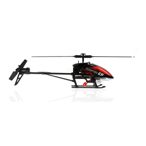
Specifications:
Main Rotor Dia. : 462mm
Tail Rotor Dia. : 113mm
Overall Length: 440mm
All-up Weight: 420g (Battery included)
Battery: 11.1V 1000mAh Li-Po
Servo: WK-7.6-6 / weight 8.5g / speed 0.09sec/60°(4.8V) / torque 0.9kg/cm (4.8V) / dimension 22.5×11.8×24mm
Features:
1) Latest 6-Axis stability enhance Control system ensures stable and precise flight , it is easy to control for both basic
flight and 3D flight, 100% decrease the difficulty of the operation.
2) High performance Brushed motor not only reduce the cost,but also ensures enough powerful to do 3D as the brushless motor.
3) Adopts 2.4 GHz technology and supports both fixed and automatic ID binding and ID assignment.
4) The RX firmware can Update Online (required UP02 upgrade cable and adapter ).
5) Telemetry function can be accomplished after update the RX firmware. The Telemetry helps you get a real time data
feedback about the Battery Voltage and the Motor Temperature .(A telemetry function Radio is a must)
Standard transmitter: DEVO-7E
Optional transmitter: DEVO-6/7/8S/10/12S
Receiver: RX2637H-D
Gyro: 6-Axis
Brush ESC: Master CP ESC
Tail Motor: 1627F
Main Motor: 380PF
Recommend Environment: Indoor and Outdoor
Recommend Experience Level: Intermediate Level
Product type: 200 size Collective Pitch Enter level helicopter
Advertisement
Table of Contents

Related Manuals for Walkera Master cp


Summary of Contents for Walkera Master cp
-
Page 1: Specifications
Gyro: 6-Axis Recommend Experience Level: Intermediate Level Battery: 11.1V 1000mAh Li-Po Brush ESC: Master CP ESC Product type: 200 size Collective Pitch Enter level helicopter Servo: WK-7.6-6 / weight 8.5g / speed 0.09sec/60°(4.8V) / torque 0.9kg/cm (4.8V) / dimension 22.5×11.8×24mm... -
Page 2: Table Of Contents
Contents 01. Forewords 08. Servo setup and adjustment 02. Safety matters needing attention 8.1 Specification and function of servo 2.1 Important Statement 8.1.1 Specification of servo 2.2 Safety matters needing attention 8.1.2 Basic function of servo (1) Far away from obstacles and people 8.2 Connection and adjustment of servos (2) Keep away from humidity 8.2.1 Connection of servos... - Page 3 10.4.1 Color decal (tracking tape) 10.4.2 Inspection and gravity center adjustment of main rotor blades 10.4.3 Tracking inspection 10.4.4 Adjustment of blade tracking 11. Flight over Appendix 1-Flight control Appendix 2 – Flight practice 1 Flight practice for the beginner 1.1Matters needing attention 1.2 Steps 2 Advanced practice...
-
Page 4: Forewords
Thank you for purchasing a Walkera radio control aircraft product. In order to quickly and safely master the operation of the Master CP RC helicopter, please read the user handbook carefully and then keep it in a safe place for future consultation and reference. -
Page 5: Safe Operation
(5) Safe operation Please fly your helicopter according to your physical status and flight skills. Fatigue, listlessness and mis-operation will increase the possibilities of accidental hazard. (6) Keep away from high-speed rotating parts Safety matters Please keep the spinning blades of both main rotor and tail rotor needing away from the pilot, people and other objects. -
Page 6: Definition Of Helicopter Orientation
In order to avoid confusion, the following sections will use the directions and orientations defined as follows.The helicopter is in front of the pilot with the tail boom and rotor closest to the pilot (tail in), the head or nose is facing forward (pointing away from the pilot).The left hand of the pilot is to the left side of the helicopter, the right hand of the pilot is to the right side of the helicopter.Its head/nose is to the front and it's tail boom is to the back. -
Page 7: Transmitter Setup
5.1 DEVO-7E(standard radio) setting 5.1.1 Boost Screen Elevator trim Throttle trim Transmission power display Battery charge indicator Model name Transmitter Timer display Model type setup display Throttle percentage value Rudder trim display Aileron trim display 5.1.2 Type Select Press ENT to get Main Menu and press UP or DN to select Model Menu. Press ENT to enter and press UP or DN to select Type Select and press ENT to enter setting interface.Press R or L to get the icon of Helicopter and press ENT to confirm, then press EXT to exit. - Page 8 5.1.7 Reverse Switch Press UP or DN to select Function Menu in Mian Menu, press UP or DN to choose Reverse Switch and press ENT to enter into Reverse Switch interface;press UP or DN to choose channel, press R or L to shift the status between normal and reverse.and press ENT to confrim and then press EXT to exit.
-
Page 9: Devo-6/7/8S/10/12S(Optional Radio) Settings
Press DN, there will interface of Curve Point, choose L M H by press R/L. press DN, there will be Output Setting. Press R/L to choose the value of point, and press ENT to confirm and then press EXT to exit. Transmitter point output... - Page 10 5.2.4 Reverse switch settings DEVO-6 DEVO-7 DEVO-8S Elevator Normal ELEV NORM Elevator Normal Aileron Normal AILE NORM Aileron Normal Throttle Normal THRO NORM Throttle Normal Rudder Normal RUDD NORM Rudder Normal Transmitter Gyro Normal GEAR NORM Gear Normal setup Pitch Normal PITCH NORM...
-
Page 11: Setup Of The Rx2637H-D Receiver
6.1 RX2637H-D receiver features (1) Adopts 2.4G DSSS technology with the functions of automatic scanning, code binding and LED receiving indication. (2) The use of a high performance receiver dramatically reduces the possibility of signal loss and ensures the accuracy and reliability of signal reception. (3) makes fine actions and powerful functions available. -
Page 12: Channel Connection Of Receiver
6.3 Channel connection of receiver AILE ELEV Setup of the RX2637H-D receiver ELEV The white wire is facing front. AILE The white wire is facing front. The white wire is facing front. Not used Not used. THRO Connects to the main motor signal wire of ESC. The white wire is facing front. Not used Not used. -
Page 13: Adjustment Of Receiver
Remove the BIND PLUG. (5) Receiver upgrade: RX2637H-D (5.1) Master CP control program upgrade can be downloaded online at Walkera Offical Website:www.walkera.com. receiver (5.2) Master CP control program upgrade tool including UP02 cable and UP02 Adapter. UP02 Adapter UP02 (5.3) Connect blue single wire plug to ELEV signal position, yellow single wire plug connect to AILE signal... -
Page 14: Instruction And Attention Of Esc
7.1 Function of brush ESC Electronic Speed Controller (ESC), mainly used in EP helicopter as a drive output device, is an electronic control circuit for the revolution speed and CW- and CCW-rotation of the motor. It will magnify the proportional signal it receives into voltage and current that can be directly exploited by the motor, the advantages of which, compared with the traditional mechanical speed controller, include compact dimension, long longevity, high efficiency and high output power. -
Page 15: Servo Setup And Adjustment
8.1 Specification and function of servo 8.1.1 Specification of servo Weight Voltage Torque Speed Dimension wk-7.6-6 8.5 g 4.8~6V 0.9kgf.cm 0.09sec/60* 22.5*11.8*24mm Servo setup 8.1.2 Basic function of servo adjustment A servo is an electro-mechanical device that converts a signal from the receiver into mechanical movement. By means of a sensor the accurate control of its direction and speed is possible. -
Page 16: Instruction And Attention Of Ga005 Balance Charger
9.1 Parameters of GA005 balance charger: Input voltage Input current Output current Dimension Weight 62.5*47*20.8mm DC15-18V 1000mA *800mA Instruction 9.2 Features of GA005 balance charger attention (1) GA005 utilizes microcomputer chips to monitor and control over the whole charging process in a balanced of GA005 way with LED indicating light to display the charging status at real time. -
Page 17: Charging Status Corresponding To Led
9.5 Charging status corresponding to LED steps Operation LED Status Charging status Insert the wall adapter into the mains power supply, and then its output is LED is in red solid lighting Power on connecting to GA005. LED is flashing in red Charging Step 1 + connect the battery to GA005 LED becomes from red to... -
Page 18: Steps Of Flight
10.1 Installation of battery Install the battery pack into the battery compartment in the direction of the arrow. Steps of flight Battery location Diagram of battery installation. 10.2 Turn on the power 10.2.1 Turn on the power 1. Install the battery pack in the battery 2. -
Page 19: Trouble Shooting A Flashing Receiver Led After Connecting The Power Cable
10.2.3 Trouble shooting a flashing receiver LED after connecting the power cable Possible causes Solutions Turn transmitter off then on and re-connect helicopter Code pairing failed. power cable. The throttle trim and throttle stick of transmitter Pull down the throttle trim and throttle stick to the are not at the lowest position. -
Page 20: Adjustment Of Main Rotor Blades
10.4 Adjustment of main rotor blades The purpose of adjustment is to make the weight and gravity center of main rotor blades equally distributing and ensure the main rotor blades are in same level during high speed spinning. 10.4.1 Color decal (tracking tape) Two different colored blade tracking decales should be placed 20mm away from each end of blade tip,whose purpose is to identify the position of each spinning blade in the following inspection of the blade tracking. -
Page 21: Adjustment Of Blade Tracking
10.4.4 Adjustment of blade tracking Below are the main course for incorrect balde tracking * Short ball linkages of (1) The weights of blades are unequal. main baldes (2) The gravity center distribution of blades is unequal. (3) The lengths of ball linkages of two blades are set improperly. (4) When blades are too loose, blades shake due to gap, or main blade connectors distort. -
Page 22: Appendix 1-Flight Control
Mode 1 (throttle stick at right hand) Appendix 1- Flight control 1. When moving the aileron stick left or right, the 2. When moving the throttle stick up or down, helicopter accordingly flies left or right. the helicopter accordingly flies up or down. 3. -
Page 23: Appendix 2 - Flight Practice
1 Flight practice for the beginner 1.1Matters needing attention (1) The beginners should be supervised and guided by skilled pilots when practicing. (2) For the sake of safety, people should keep at least 5 meters away from the helicopter during practicing. (3) Choose a spacious ground without people and obstacles as the flight practice field. -
Page 24: Advanced Practice
2 Advanced practice 2.1 Frog-hopping practice Repeat the take off and landing action using the throttle stick whilst maintaining a vertical path. Increase your rate of ascent and descent gradually as you become more comfortable with the exercise. Be sure to slow down in time when landing! Appendix 2 –... -
Page 25: Aerobatic Flight
2.5 Aerobatic flight Your Master CP can perform breathtaking and exciting aerobatic flight such as dives and inverted 3D. Inverted flight Mode 1 (throttle stick at right hand) Appendix 2 – Flight practice 1. When moving the aileron stick left or right, 2.
Need help?
Do you have a question about the Master cp and is the answer not in the manual?
Questions and answers