GBC Ultima 65 Service Manual
Hide thumbs
Also See for Ultima 65:
- User manual ,
- Instruction manual (71 pages) ,
- Operating instructions manual (45 pages)

Related Manuals for GBC Ultima 65


Summary of Contents for GBC Ultima 65
- Page 1 SERVICE MANUAL ULTIMA 65 GBC National Service Department Printed in U.S.A Part Number 1722768 Assembly Number 1711501 Issued 01/02 Revision: C © Copyright General Binding Corporation, Northbrook, IL U.S.A...
- Page 2 THIS PAGE INTENTIONALLY LEFT BLANK...
-
Page 3: Table Of Contents
Mechanical Operation 5.5 General Troubleshooting 5.6 Testing Electrical Components 5.7 Troubleshooting Guide Chart 5.8 Electrical Wiring Diagram and Schematics 5.8.1 Ultima 65 Wiring Schematic 5.8.2 Ultima 65 Wiring Diagram Disassembly / Assembly / Adjustments Film Roll Tension Adjustment Roller Pressure Adjustment... - Page 4 TABLE OF CONTENTS PAGE Parts List Ultima 65 Parts List 8.1.1 Cover Assembly and Film Roll Support Shafts 8.1.2 Case and Tray Assembly 8.1.3 Left Side Assembly 8.1.4 Right Side Assembly 8.1.5 Frame Assembly 8.1.6 Roller Assembly 8.1.7 Control Panel Assembly 8.1.8 Safety Lever Assembly...
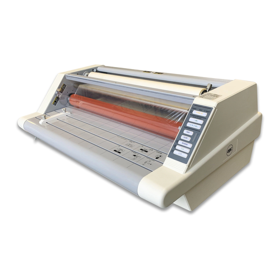
- Page 5 Ultima 65 series laminator will provide you with high quality lamination and versatility, at an affordable price. The Ultima 65 will give customers a simple to use laminator that has the ability to laminate GBC’s latest film product, the Ultima 1 mil film. Ultima film provides superior adhesion and higher gloss for better clarity.
-
Page 6: Specifications
2.0 SPECIFICATIONS 115 VAC MODEL 230 VAC MODEL Required 120 VAC +/-10% – Two Wire 230 VAC +/-5% Two Wire Power Service Plus Ground Service Plus Ground Supply: 15 Amps, 60 Hz 7.8 Amps, 50 Hz Single Phase Single Phase Electrical 120 VAC, 15 Amps 230 VAC, 7.8 Amps... - Page 7 3.0 INSTALLATION Closely inspect the unit prior to opening. All shipping damage should be brought to the immediate attention of the delivering carrier. Place the laminator on a stable flat surface capable of supporting at least 95 lbs. The surface should be at least 30 inches high to assure comfortable positioning during operation.
- Page 8 GBC Ultima 65 Laminator Helpful operating hints for safe, quality lamination LOCATION OF THE LAMINATOR Position your laminator away from drafts that can affect roller temperature. FILM LOADING TIPS It is recommended that LOADING and UNLOADING be performed when the laminator is COLD.
- Page 18 4-10...
-
Page 19: Troubleshooting
A basic understanding of the theory of successful lamination is required for all personnel servicing the Ultima 65. Theory of Successful Lamination To obtain the ultimate in a successful laminate, three factors should be present: 1. -
Page 20: Electrical System
5. Thermocouple (TSA1): The temperature sensor provides a heat reference for the Main PCB (PCB1). This sensor should read a short when cold. Ultima 65 has 1 wrap capton tape. These sensors should be soldered and have no air pockets. -
Page 21: Motor Control Circuit
5.0 TROUBLESHOOTING 5.3.1 Heater Control Circuit (Continued) 6. Thermal cutoff (TCO1): Provides overheat protection of the heater circuit. Earlier versions have a resettable type TCO and the current production models have a non- resettable type TCO. These TCO’s should always read a short and will trip when the TCO reaches a temperature of 248°F (120°C). -
Page 22: General Troubleshooting
WARNING! POSSIBILITY OF ELECTRICAL SHOCK WHEN TESTING ELECTRONIC COMPONENTS. SERVICE SHOULD BE PERFORMED BY QUALIFIED GBC SERVICE TECHNICIANS ONLY. PLEASE CALL GBC FOR SERVICE 1-800-790-7787. Testing Electrical Components All electrical components can be tested by using a variety of test equipment to check for continuity, resistance, voltage and amperage. -
Page 23: Troubleshooting Guide Chart
5.0 TROUBLESHOOTING 5.7 TROUBLESHOOTING GUIDE CHART SYMPTOM PROBABLE MALFUNCTION CORRECTIVE ACTION No power. No outlet power. Check outlet for correct voltage. Power cord disconnected. Connect power cord. Blown fuse. Check continuity, replace if needed. Tripped circuit breaker. Reset circuit breaker. Tripped TCO. - Page 24 Incorrect roller pressure. Adjust roller pressure. Consistent wrap-ups, Dirty rollers. Follow “Caring For Your Laminator” adhesive marks in section 4.0 Operating Instructions. on product. SERVICE SHOULD BE PERFORMED BY QUALIFIED GBC SERVICE TECHNICIANS ONLY. PLEASE CALL GBC FOR SERVICE 1-800-790-7787.
-
Page 25: Electrical Wire Schematic
ULTIMA 65 ELECTRICAL WIRE SCHEMATIC (120VAC) -
Page 28: Roller Pressure Adjustment
The film tension is set at the factory. Tension adjustments are not necessary if you are using 1.5 or 3-mil GBC film, unless the lamination is curling up or down. Generally, 5 and 10-mil film requires more tension; and, as the film roll becomes smaller, tension increases, requiring more adjustments. - Page 29 6.0 ADJUSTMENTS 6.2.1 Ultima 65 Roller Pressure Adjustment (Continued) 1. Turn machine off. 2. Remove right and left side covers. 3. Adjust the rear Pull Rollers. The eyebolt on the right and left side should be tightened until only 4-5 threads are showing above the adjusting nut.
-
Page 30: Main Pcb (Pcb1) Calibration Procedure
6.3 Main PCB (PCB1) Calibration Procedure The Main PCB must be calibrated when replaced. To calibrate the PCB use the calibration fixture GBC P/N 706111164, and follow the calibration procedure outlined below. Calibration must be performed with the new board installed in the machine. - Page 31 6.0 ADJUSTMENTS 6.4 Main PCB (PCB1) Calibration Procedure 15. Reconnect the thermal sensor to the Main PCB. 16. Turn Laminator on. Place the beaded thermocouple in the center of the nip rollers (or infrared temperature sensor pointed right at the nip). Adjust SV2 until the ready light illuminates and the nip temperature is 290°F.
- Page 32 ALTERNATIVE ULTIMA 65 CALIBRATION Adjust SV1 to 60 ohms at the points shown below. Do this with the machine cold and the P.C. Board removed from machine. Figure 1...
- Page 33 Read the nip temperature, at this point, each full rotation counterclockwise will increase the nip by 5° F to 10° F. Or if needed, rotation clockwise will decrease the nip temperature. Do this to reach desired nip temperature. GBC Lamination Specialist Mike Taylor sent in this Alternative Calibration Procedure.
- Page 34 6.0 ADJUSTMENTS 6.4 Disassembly/Assembly Procedure The disassembly of the Ultima 65 is described in the following steps. Use section 8.0 as a reference to help you understand the text. Reassemble in reverse order. Note: Disconnect the unit from the 120VAC receptacle before performing any disassembly procedures.
- Page 35 6.0 ADJUSTMENTS 6.4.2 Pull Roller Disassembly Remove Feed Table. Remove (4) Phillips Screws from Right Side Plate and remove Right Cover. Remove (4) Phillips Screws from Left Side Plate and remove Left Cover. Remove (3) Phillips Screws from Right Side Plate securing Upper Rear Cover. Remove (3) Phillips Screws from Left Side Plate securing Upper Rear Cover and remove Upper Rear Cover.
-
Page 36: Maintenance
7.0 Maintenance External Cleaning 7.1.1 External Surfaces DISCONNECT POWER PRIOR TO CLEANING EXTERNAL SERVICES. Clean external surfaces of the laminator with a soft cloth moistened with a mild solution of detergent (such as dish washing liquid) and warm water. Do not use chemical cleaners or solvents, as these have a harmful effect on painted surfaces. -
Page 37: Parts List
8.0 PARTS LISTS All parts in each illustration are keyed with an index number for reference to the respective part number, part name, and quantity in the parts list. When ordering service parts, always include the following information: Machine Model Number Machine Serial Number Part Number Part Name... - Page 38 8.1.1 COVER ASSY. AND FILM ROLL SUPPORT...
- Page 39 8.1.1 COVER ASSY. AND FILM ROLL SUPPORT GMP # ITEM GBC # DESCRIPTION 1712109 RETAINING RING 701090705 1711620 ROLLER COVER 601230453 1711621 TAKING BAR FOR ROLL COVER 603030611 1711629 BUSHING 613030306 1711622 FILM GUIDE SCREEN/UPPER 601220131 1711627 HEX FILM SHAFT...
-
Page 40: Case And Tray Assembly
8.1.2 CASE AND TRAY ASSEMBLY... -
Page 41: Case And Tray Assembly
8.1.2 CASE AND TRAY ASSEMBLY ITEM GBC# GMP# DESCRIPTION 1711658 RIGHT SIDE COVER 604022002 1720584 FIXING KNOB FOR PAPER GUIDE 604022032 1720583 PAPER GUIDE 604022031 1711657 LEFT SIDE COVER 604022001 1711634 FRONT TABLE 604036021 1711633 LEVER CAP FOR FRONT TABLE... -
Page 42: Left Side Assembly
8.1.3 LEFT SIDE ASSEMBLY... -
Page 43: Left Side Assembly
8.1.3 LEFT SIDE ASSEMBLY ITEM GBC# GMP# DESCRIPTION 1711592 FILM TENSION LEVER 601310505 1712140 BRAKE PAD 703070101 1711577 TENSION PLATE FRICTION DISC 703070111 1720546 FIBER TENSION PLATE 601230702 1711637 ADJUSTMENT BOLT FOR FILM TENSION 603030537 1711635 BRAKE HUB 601230713 1711593... -
Page 44: Right Side Assembly
8.1.4 RIGHT SIDE ASSEMBLY... -
Page 45: Right Side Assembly
8.1.4 RIGHT SIDE ASSEMBLY ITEM GBC# GMP# DESCRIPTION 1720524 DC MOTOR 609020200 1711571 STEEL SPROCKET, 12T * F12 701080266 1711572 STEEL SPROCKET, 12T * F10 701080265 1711573 CENTER PIN FOR IDLER GEAR 613030540 1711574 CHAIN 701070150 1711575 IDLE GEAR SUPPORT... -
Page 46: Frame Assembly
8.1.5 FRAME ASSEMBLY... -
Page 47: Frame Assembly
8.1.5 FRAME ASSEMBLY ITEM GBC# GMP# DESCRIPTION 1711554 TRIAC 07050703 1711555 SUPPORT BAR 603030151 1712594 TRANSFORMER, (OUTPUT 3-32 VDC) 610010206 1712595 TRANSFORMER (EUROPE) 610010207 1711558 TRANSFORMER (UK) 610010209 1711561 UPPER REAR COVER 601230451 1711562 LOWER REAR COVER 601230452 1711560 RIGHT SIDE PLATE... - Page 48 8.1.6 ROLLER ASSEMBLY 8-11...
-
Page 49: Roller Assembly
8.1.6 ROLLER ASSEMBLY ITEM# GBC # GMP # DESCRIPTION 1711617 SPROCKET 701080233 1711616 RIGHT TENSION LEVER FOR PULL ROLLERS 601310510 1712049 HOUSING FOR DRY BEARING 601230804 1711614 UPPER IDLER ROLLER 603030161 1711596 PULL ROLLER 607040561 1711597 BEARING FLANGE 701050240 1711598... - Page 50 8.1.7 CONTROL PANEL ASSEMBLY 8-13...
-
Page 51: Control Panel Assembly
8.1.7 CONTROL PANEL ASSEMBLY ITEM# GBC# GMP# DESCRIPTION 1711645 CONTROL PANEL STICKER 802104002 1711646 PLASTIC SWITCH PANEL 703020221 CONTROL KEY, STAND BY, YELLOW 703020501 CONTROL KEY, 1 MIL, GREEN 703020502 CONTROL KEY, 1.5 & 3 MIL, GREEN 703020503 CONTROL KEY, FAST, BLACK... -
Page 52: Safety Lever Assembly
8.1.8 SAFETY LEVER ASSEMBLY ITEM# GBC# GMP# DESCRIPTION 1712074 LEVER FOR FRONT TABLE 613030613 1711638 LEVER GUIDE FOR FRONT TABLE 601310511 1711636 RETAINING RING 701090721 1712612 COMPRESSION COIL SPRING 701090160 1911303 MOUNTING SCREWS (NOT SHOWN) 1911303 (USE GMP PART NUMBERS WHEN ORDERING PARTS) -
Page 53: Cutter Assembly
8.1.9 CUTTER ASSEMBLY ITEM# GBC# GMP# DESCRIPTION 1711567 706111049 SLITTER ASSEMBLY (1-6) 1712134 701110101 1720586 SLITTER LEVER 604022034 1154019 SLITTER BLADE 1154019 1711641 SCREW 701104803 1712611 TENSION COIL SPRING 701090159 1720585 SLITTER HOUSING 604022033 (USE GMP PART NUMBERS WHEN ORDERING PARTS) -
Page 54: Recommended Spare Parts List
As your machine base grows, your stocking levels will also grow. NOTE: This is a list of high usage parts only. Less frequently used and incidental parts should be determined and stocked at your discretion. GBC# GMP# DESCRIPTION... -
Page 55: Additional Information
10.0 ADDITIONAL INFORMATION This section contains information released after the manual was published. All information pertinent to this unit should be inserted in this section whether it is published in a National Service Bulletin or obtained from any other source. 10-1... - Page 56 FROM: NATIONAL SERVICE DEPARTMENT Page: 1 of 1 SUBJECT: ULTIMA 65 TRIAC TEST AND Date: 09/07/98 ROLLER PRESSURE ADJUSTMENT TRIAC TESTING: When testing the Triac it must be tested out of the circuit and at room temperature. Use an Ohm meter to take the readings between the leads as follows.
- Page 57 The following is a copy of the September 1997 issue, vol. 1, EAGLE EYE TECHNICAL INFORMATION bulletin published by the Color Finishing Division. It offers excellent information and procedures for determining problems associated with GBC’s new Color Finishing Laminators. Please review and ad this NSB to your Ultima65 and Eagle Series Service Manuals.
- Page 58 IN THE BEGINNING GBC’s evolution in the laminators has taken the knowledge of lamination to a higher level than ever before. The new GBC Color Finishing Laminators have distinctive characteristics that their older predecessors did not have. With the flexibility to use a wide range of thermal and cold Pressure Sensitive Adhesive (PSA) films, the word lamination takes on new meanings.
- Page 59 Some copiers/printers use water-soluble toner, while others like XEROX use fuser oil to fix the image to the paper. Fuser oil may not allow conventional laminating film to adhere to the paper. In most cases, GBC thermal HI-TAC film solves the problems of excessive fuser oil. ROLLER PRESSURE BY THE FOOTPRINT A laminator’s footprint can visually provide a quick assessment of roller pressure.
- Page 60 4. Disconnect heat coil wires attached to ceramic end of the heater tube. The heater tube is inside of the heat roller. 5. Disconnect thermal cutout (TCO) wires attached to the TCO by spade terminals. 6. Remove top and bottom green silicone heater holders (one side only). 7.
- Page 61 SEE DISTRIBUTION N.S.B. NO: 210K FROM: NATIONAL SERVICE DEPARTMENT Page: 1 of 1 SUBJECT: ULTIMAS & EAGLES INSTALLATION Date: 2/28/00 Installation of Eagles and Ultima machines should include removing the side panels and checking for any loose screws and/or connections, particularly on the P.C. Boards. This should also be a standard procedure when performing service on any of these models.
- Page 62 This N.S.B obsoletes N.S.B 248, dated 5/15/00 Ultima 65’s with heat problems (gray roller machines) will no longer be traded in. The parts the technician will need to order to bring the Ulitma 65 to current specs are listed below. Part Number 1722626 has been assigned to the upgrade kit.
- Page 63 GMP LAMINATION CALIBRATION FIXTURES Date: 05/09/01 GBC Service Parts Dept is currently stocking the Calibration Fixture part number 1700407. Once the inventory has been depleted, the Service Parts Dept will be stocking a new Universal Type “A” Calibration Fixture. This Calibration Fixture part number 706111164 can be used on all current GMP Laminators, including the Pouch Laminators.
- Page 64 NATIONAL SERVICE BULLETIN Professional Support Services 500 Bond St. Lincolnshire, IL. 60069 SEE DISTRIBUTION N.S.B. NO: 210P FROM: NATIONAL SERVICE DEPARTMENT Page: 1 of 1 SUBJECT: ULTIMA-65 INFRARED HEATER ASSEMBLY Date: 02/11/02 This NSB supersedes and obsoletes NSB 210N, dated 4/25/01. Listed below are the individual components for the Ultima-65 Infrared Heater Assembly.
- Page 65 NATIONAL SERVICE BULLETIN Professional Support Services 500 Bond St. Lincolnshire, IL. 60069 SEE DISTRIBUTION N.S.B. NO: 210Q FROM: NATIONAL SERVICE DEPARTMENT Page: 1 of 1 SUBJECT: ULTIMA-65 TURNING OFF WHILE RUNNING Date: 6/21/02 When you encounter an Ultima-65 turning off while running, here are some things that you should know: •...
- Page 66 Date: 07/18/02 HEATER JUMPER WIRES W/CONNECTORES Part number 704161716 is for the Ultima 65 Heater Jumper Wires with Eyelet Connectors. Part number 704161803 is for the Eagle 35, 65, 105 Heater Jumper Wires. These wires connect to the ceramic ends of the infrared heaters.
Need help?
Do you have a question about the Ultima 65 and is the answer not in the manual?
Questions and answers
The laminator rolls have stopped rolling.