Table of Contents
Advertisement
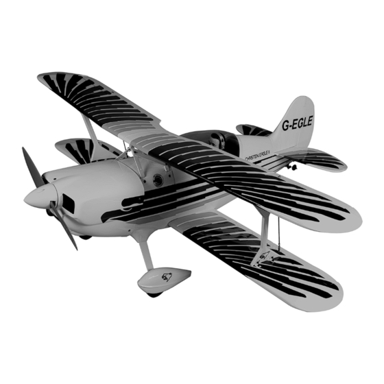
CHRISTEN
ASSEMBLY MANUAL
MS:104
Specifications
Wing span --------------------------------------- 53.9 in ----------------------------- 137cm.
Wing area --------------------------------------- 922.3 sq.in ------------------ 59.5 sq.dm.
Weight -------------------------------------------- 8.4-9.9 lbs --------------------3.8-4.5 kg.
Length -------------------------------------------- 47.4 in --------------------------- 120.5cm.
Recommended engine size ---------- 0.75-.91 cu.in ------------------------- 2-stroke.
ELECTRIC CONVERSION : OPTIONAL.
Radio System required 6 channel with 6 digital servos.
Flying skill level ---------------------Intermediate/advanced.
Kit features.
•
Ready-made—minimal assembly & finishing required.
•
Ready-covered covering.
•
Photo-illustrated step-by-step Assembly Manual.
Made in Vietnam.
EAGLE II
--------------0.91-1.00 -1.25cu.in---------------- 4-stroke.
Advertisement
Table of Contents

Related Manuals for Factory CHRISTEN EAGLE II

Summary of Contents for Factory CHRISTEN EAGLE II
- Page 1 CHRISTEN EAGLE II ASSEMBLY MANUAL MS:104 Specifications Wing span --------------------------------------- 53.9 in ----------------------------- 137cm. Wing area --------------------------------------- 922.3 sq.in ------------------ 59.5 sq.dm. Weight -------------------------------------------- 8.4-9.9 lbs --------------------3.8-4.5 kg. Length -------------------------------------------- 47.4 in --------------------------- 120.5cm. Recommended engine size ---------- 0.75-.91 cu.in ------------------------- 2-stroke. --------------0.91-1.00 -1.25cu.in---------------- 4-stroke.
-
Page 2: Instruction Manual
Thank you for choosing the CHRISTEN EAGLE II ARTF by SEAGULL MODELS. The CHRISTEN EAGLE II was designed with the intermediate/advanced sport flyer in mind. It is a semi scale airplane which is easy to fly and quick to assemble. The airframe is conventionally built using balsa, plywood to make it stronger than the average ARTF , yet the design allows the aeroplane to be kept light . -
Page 3: Hinging The Ailerons
Hinge. gluing! This will ensure proper as- sembly as the CHRISTEN EAGLE II is made from natural materials and minor adjustments may have to be made. The paint and plastic parts used in this kit are fuel proof. -
Page 4: Hinging The Elevators
CHRISTEN EAGLE II Instruction Manual. 6) Using C/A remover/debonder and a LOWER MAIN WING( UPPER SIZE). paper towel, remove any excess C/A glue that may have accumulated on the wing or in the aileron hinge area. 7) Repeat this process with the other wing panel, securely hinging the aileron in place. - Page 5 www.seagullmodels.com UPPER MAIN WING( LOW SIZE). 2 sets. 3x40mm. CONTROL HORN M3 SCREW Epoxy. ALUMINUM WASHER ALUMINUM WASHER M3 LOCK 4 pcs. M3x10mm. 18mm Epoxy. Aileron control horn. Wing bottom. ELEVATOR CONTROL HORN. M3x10mm. M3x10mm. Install the elevator control horn using the same method as with the aileron control horns.
-
Page 6: Rudder Control Horn
CHRISTEN EAGLE II Instruction Manual. CONTROL HORN CONTROL HORN M3 M3 SCREW Aluminum Washer ALUMINUM WASHER Epoxy EPOXY. Horizontal Elevator. Stabilizer. Rudder FUSELAGE Aluminum Washer M3 LOCK NUT ALUMINUM WASHER M3 LOCK NUT Epoxy. Horizontal Stabilizer. EPOXY. Rudder. Fuselage. 16mm... -
Page 7: Installing The Stopper Assembly
www.seagullmodels.com Mark and drill 4 holes for engine mount. Insert 4 blind nuts to firewall. 5.5mm. M3X15mm. Vent tube Fuel pick up tube. M4x30mm. Fuel fill tube INSTALLING THE STOPPER ASSEMBLY. Carefully use a lighter or heat gun to 1) Using a modeling knife, carefully cut permenently set the angle of the vent tube. -
Page 8: Fuel Tank Installation
CHRISTEN EAGLE II Instruction Manual. FUEL TANK INSTALLATION. Vent tube. Glow Engine. You should mark which tube is the vent and which is the fuel pickup when you attach fuel tubing to the tubes in the stopper. Once the tank is installed inside the fuselage, it may be difficult to determine which is which. -
Page 9: Installing The Main Landing Gear
www.seagullmodels.com wheel collar. Axle. Washer. wheel. Locker glue. wheel. wheel collar. Washer. nut. Axle. wheel Pant. 2) A drop of C/A glue on the wheel collar screws will help keep them from coming lose during operation. Repeat the process for the other wheel. Landing Gear. - Page 10 CHRISTEN EAGLE II Instruction Manual. M4 x 20mm.
-
Page 11: Installing The Battery
www.seagullmodels.com C/A glue. M4 x 30mm. Pushrod wire. INSTALLING THE BATTERY. Battery. Pushrod wire. COWLING. Tie wrap. MOUNTING THE ENGINE. M3 x 10mm. Trim and cut. 140mm. Trim and cut. 4.2mm diameter. Trim and cut. - Page 12 CHRISTEN EAGLE II Instruction Manual. M3 x 10mm. Epoxy. 140mm M3 x 10mm. Electric Conversion (Ep Power) (OPTION). Balsa block. Electric motor. Epoxy. 5.2mm diameter. Epoxy.
-
Page 13: Installing The Spinner
www.seagullmodels.com Speed control. INSTALLING THE SPINNER. Install the spinner backplate, propeller and spinner cone. The propeller should not touch any part of the spinner cone. If it does, use a sharp model- ing knife and carefully trim away the spinner cone where the propeller comes in contact with Electric motor. -
Page 14: Installing The Aileron Servos
CHRISTEN EAGLE II Instruction Manual. INSTALLING THE AILERON SERVOS. Wing rib. Wing. Small Weight. Small Weight. String. String. Attach the string to the servo lead and carefully thread it though the wing. Wing. AILERON PUSHROD HORN INSTALLATION 70mm. M3 clevis. -
Page 15: Installing The Horizontal Stabilizer
www.seagullmodels.com THROTTLE SERVO ARM INSTALLATION. Wing. M3 lock nut. ) Install adjustable servo connector in the servo arm as same as picture below: Adjustable Servo connector. Servo arm. Nut. Aileron. Repeat the procedure for the other wing. Throttle servo . Elevator servo . -
Page 16: Installing The Vertical Stabilizer
CHRISTEN EAGLE II Instruction Manual. Epoxy. INSTALLING THE VERTICAL STABILIZER. Trim and cut. Pen. Epoxy. Trim and cut. Epoxy. - Page 17 www.seagullmodels.com Rudder control horn . C/A glue. Hinge. Elevator control horn M2 lock nut. Masking tape. Elevator pushrod . ELEVATOR - RUDDER PUSHROD - CONTROL HORN INSTALLATION. Metal clevis Elevator control horn . M2 clevis. M2 Lock nut. Attach to elevator - rudder control horn. Attach to servo arm in fuselage.
-
Page 18: Mounting The Tail Wheel
CHRISTEN EAGLE II Instruction Manual. Elevator Pushrod. Rudder. servo rudder Throttle. Servo elevator. MOUNTING THE TAIL WHEEL. See picture below. M3 x 12mm. M3 x 12mm. Trim and cut. Epoxy. -
Page 19: Installing The Receiver
www.seagullmodels.com INSTALLING THE RECEIVER. 1) Plug the six servo leads and the switch lead into the receiver. Plug the battery pack Wing bolts. lead into the switch also. 2) Wrap the receiver and battery pack in the protective foam rubber to protect them from vibration. - Page 20 CHRISTEN EAGLE II Instruction Manual. M3 x 10mm. M3 x 20mm. M3 x 10mm. M3 x 10mm.
- Page 21 www.seagullmodels.com...
-
Page 22: Control Throws
Ifthis is not possible or does not correct it, 1) We highly recommend setting up the sticksmall amounts of lead weight on the CHRISTEN EAGLE II using the control throws fuselagesides under the horizontal stabilizer. listed at right. We have listed control throws If the tailof the plane falls, the plane is tail heavy. - Page 23 Do not use the aerobatic settings for initial test flying or sport flying. 2) Check every bolt and every glue joint in the CHRISTEN EAGLE II to ensure that ev- erything is tight and well bonded. 4) By moving the position of the adjust-...
Need help?
Do you have a question about the CHRISTEN EAGLE II and is the answer not in the manual?
Questions and answers