Table of Contents

Subscribe to Our Youtube Channel
Related Manuals for Smith-Root LR-24


Summary of Contents for Smith-Root LR-24
- Page 1 Smith-Root continues to be the leader in effective, safe, and reliable technology for fisheries conservation. Knowledgeable biologists have depended upon Smith-Root equipment since 1964. USER'S MANUAL LR-24 ELECTROFISHER #07288.06...
-
Page 2: Table Of Contents
CONTENTS USER'S MANUAL INTRODUCTION SECTION 4: SAFETY FEATURES The LR-24 Electrofisher ........1 Emergency Shutdown Switch ....19 OVERVIEW Quick Release Packframe ......19 Flashing Red Light ........19 General Information ......... 2-4 Audio Alarm ..........20 SECTION 1: STATUS DISPLAY Anode Switch ..........20 Input ..............5... - Page 3 The restocking fee is figured at 10% of the purchase price but not less than $20.00. Customers receiving equipment in damaged condition will be referred to the shipping company for insurance reimbursement. 07288 User's Manual LR-24, Rev.06 © 2013 Smith-Root, Inc. Vancouver, WA - USA www.smith-root.com...
-
Page 4: Introduction
Taking the time to familiarize yourself with these features will go a long way towards learning how to use the LR-24 in the most efficient manner. ATTENTION! Before getting started electrofishing, make sure... -
Page 5: General Information
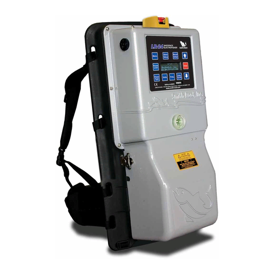
A molded strain relief allows the anode cable to pass through slots on either side of the battery cover. 12- IMMERSION SENSOR This sensor will shut the unit down should the LR-24 be immersed in water. 13- SERIAL NUMBER Unique number to identify the unit for service. -
Page 6: Overview
H - VOLTS KEY Displays and allows the modification of the voltage setting. I - FREQ. KEY LR-24 Key pad with fluorescent display Displays and allows the modification of the output frequency setting. A - MENU KEY J - DUTY CYCLE KEY Displays the system menu options. - Page 7 • Pack suspension system allows for maximum flexibility and comfort. • Precise control over the output helps reduce injuries to fish. • Power limit mode allows the user to set a maximum output power level that the LR-24 will not exceed.
-
Page 8: Input
SECTION 1 USER'S MANUAL SECTION 1: STATUS DISPLAY When first turning on the LR-24, a screen will briefly appear displaying the model number, software version, and Smith-Root, Inc.'s web address. The status display screen will automatically appear after a few seconds. -
Page 9: Status Display
LR-24 BACKPACK ELECTROFISHER SECTION 1: STATUS DISPLAY (CONT.) 3.) WAVEFORM SCREEN A sample waveform screen is shown in Figure 1.3. Output Waveform The first line will have 'Output Waveform', unless dual Store Recall Store Recall Standard Pulse Menu Menu Setup... -
Page 10: Display Panel
60 Hz with 25% duty cycle, an output pulse will occur Fig. 2.2 60 times per second (once each 16.7 mSec) with a pulse width of 0.25 X 16.7 mSec. = 4.2 mSec, and a gap between pulses of 0.75 X 16.7mSec. = 12.5mSec. www.smith-root.com... -
Page 11: Display Panel
Duty Freq. Cycle LR-24 BACKPACK ELECTROFISHER SECTION 2: DISPLAY PANEL (CONT.) DOWN ARROW KEY Decreases the selected setting or scrolls down through a Store Recall menu or scrolls to the next status display. Setup Setup ENTER KEY Selects menu items or enters settings into the selected Enter function and then returns you to the main status display. -
Page 12: System Menus 1-9
30Hz 12% duty cycle and will System Menu adjust the output voltage as necessary to reach 25 watts Run Quick Setup? average power output. While the LR-24 sets its output up Store Recall Menu Menu... - Page 13 This menu item allows the user to select the method for controlling the maximum average output power of the LR-24 (Fig. 2.9). If the user-set power limit is reached, the LR-24 will automatically decrease the output voltage or frequency, as selected by the user, to maintain the output power at that limit.
- Page 14 Limiting on or off (Fig. 2.10). On hot days, when the Enable Thermal Power Foldback? LR-24 is putting out 200 watts or more, it may eventually overheat and shutdown to prevent possible damage to the electronics. Thermal Power Limiting allows the LR-24 to Fig.
- Page 15 When it is finished, the output of the LR-24 will automatically turn off. *1st Test Passed* Connect Electrodes If the LR-24 passes this part of the test this message will to Test Load, Close be displayed. (Fig. 2.18) Pole Switch...
- Page 16 LR-24 (Fig. 2.21). Fig. 2.21 This history file is an aid to troubleshooting if the LR-24 develops a problem. There is a table of error codes in Code:UO3, 6681S Appendix B of this manual (page 51).
-
Page 17: Power Limit
Power Power Enter Enter Enter Limit Limit Limit voltage limit is reached and the power limit is still being Power exceeded, the LR-24 will shutdown its output and an error Power Enter Enter Enter Limit Limit Pulse Duty Pulse Duty... - Page 18 10 pulses of the 400 Hz burst because 400 Hz is only 10 times the cycle frequency of 40 Hz. As a second example, if the LR-24 were set to produce a burst of 5 pulses at 250 Hz and 10% duty cycle at a...
- Page 19 The following example demonstrates how to set up a Burst 150V of Pulses: 1. Press the Pulse Type key on the front of the LR-24. Use the Arrow keys to select Burst of Pulses for the new Fig. 2.26 pulse type. The display will look like Figure 2.25.
- Page 20 Therefore, settings are 150 volts for 5 pulses/burst. The individual burst frequency is 400Hz, whereas the group frequency is 40Hz. Duty Cycle is 25%. www.smith-root.com...
-
Page 21: Battery Compartment
(Fig. 3.2). It mates with an identical connector on the LR-24 battery packs. This connector is color coded and polarized to prevent accidental reverse connections of the battery. For lithium batteries, the provided adapter must be used (Fig. -
Page 22: User's Manual
The large red mushroom switch located on the top of the LR-24 is the Emergency Shutdown Switch, which is also the main on/off switch for the LR-24 (Fig. 4.1). To turn the power on, the user must rotate the switch 90 degrees in the direction of the arrows (clockwise). -
Page 23: Safety Features
2. Don’t continue to above. electrofish if boots or 4. Dual Output mode: In this mode, the LR-24 can oper- gloves get wet inside. ate with a primary or secondary user-specified voltage/ 3. Don’t operate an waveform combination. -
Page 24: Tilt Switch
TILT SWITCH The tilt switch automatically turns off the output of the LR-24 if the LR-24 is tipped too far from vertical in any direction. The maximum forward tilt is 50 degrees, backward tilt is 40 degrees, and side tilt is 45 degrees, all 40°... -
Page 25: Battery Compartment Interlock Switches
The cover of the battery compartment contains an TEMPERATURE interlock mechanism (A) that automatically turns off power to the LR-24 if the cover is opened. When replacing the battery compartment cover, *****ERROR***** adjust it so that it is on the inside of the molded Over Temperature guides (B) of the pack frame. -
Page 26: Peak Current Overload
The LR-24 must then be sent back to Smith-Root Fig. 4.11 for repair. Do not attempt to use the LR-24 if this message appears, as a safety hazard may exist and further use may cause more damage to the LR-24. -
Page 27: Inverter Overload
If the input current measuring circuit does not measure any current, this error message will appear and the power to the LR-24 will have to be turned off and back on to clear the message (Fig. 4.14). This test is included to detect problems in the input current sensing circuit. - Page 28 BASIC SETUP OF THE LR-24: 1. Make sure the power switch on the top of the LR-24 is in Fig. 5.1 the OFF position (pressed DOWN).
- Page 29 If the tilt message Return to upright position to clear. does not appear, do not use the LR-24; send it to Smith- Root for repair. Fig. 5.4 6. Place a dampened cloth on the immersion sensor contacts...
- Page 30 RECOMMENDED ADJUSTMENTS TAXIS AND TETANY There may be some confusion Quick Setup adjusts the LR-24 to produce 30 Hz, 12% between taxis and tetany. Taxis is duty cycle at 25 watts average output power. This an induced swimming action. The...
-
Page 31: Setup
The display will show one setup at a time (Fig. Power Enter Enter 5.9). When the end of the waveform list is reached, the Limit LR-24 will wrap around to the beginning of the list. Duty Pulse Duty Volts Freq. -
Page 32: Factory Default Stored Waveforms
10. Dual output mode waveform: Primary waveform - Burst of three pulses at 4Hz with 25% duty cycle, 1Hz cycle frequency, 100 volts, 400 watt power limit. Secondary waveform - Standard Pulse 30 Hz, 25% duty cycle, 100 volts, 400 watt power limit. www.smith-root.com... -
Page 33: Custom Setup Procedure
32), if this is to be the selected pulse type. Refer to the procedures (1-4) in the setup section (page 25). 1. When you turn on the LR-24, it recalls the waveform setting Voltage that was in use when the LR-24 was previously turned off. - Page 34 NOTE: Duty cycle and frequency can have a huge impact on taxis. In general, lower frequencies are safer for fish than higher frequencies. If you are not getting any response from fish, change the LR-24 settings according to adjustments a, b, and c on page 27. www.smith-root.com...
-
Page 35: Burst Of Pulses Waveforms
In general, lower frequencies are safer for larger 400W fish than higher frequencies. If you are not getting any response from fish, change the LR-24 settings according to adjustments a, b, and c on page 27. Fig. 5.21... -
Page 36: Dual Output Mode
This feature quickly allows the user to change the output of the LR-24. Users may wish to do this if, for example, they are working Pulse Type with juveniles and you suddenly come across an adult. - Page 37 150V In general, lower frequencies are safer for larger fish than higher frequencies. If you are not getting any response from fish, change the LR-24 settings according to adjust- Fig. 5.27 ments a, b, and c on page 27. www.smith-root.com...
-
Page 38: Storing Waveform Settings
100 Volts might work particularly well at different sampling sites. This can simplify setting up the LR-24 when you return to that Fig. 5.28 site later to sample again. This reduces variability caused by slightly different setups used by different crews. -
Page 39: Lr-24 Specifications
LR-24 BACKPACK ELECTROFISHER SECTION 5: SETUP AND OPERATION (CONT.) LR-24 SPECIFICATIONS* Conductivity Range 10-2150 microsiemens per centimeter Input Voltage 24 VDC Nominal Input Current 20 Amps Max. Battery voltage and current plus easy to read fuel Input Monitoring gauge type display for battery voltage Output Voltage 50 to 990 Volts in 5 volt steps Output Current 4 Amps continuous at 100 Volts, 40 Amps peak max. -
Page 40: My Custom Waveforms
Primary waveform and one for the Secondary waveform. If it becomes necessary to send the Electrofisher in for repair, these settings may be lost and would need to be re-entered in the system. Duty Cycle Frequency Storage Pulse Type (DC, Voltage (Burst/No. Location Standard, Burst) (Burst/Cycle) Pulses) www.smith-root.com... -
Page 42: Charger
USER'S MANUAL SECTION 6: BATTERY CARE AND MAINTENANCE The Universal Battery Charger (UBC- 24) is designed to charge lead-acid and lithium batteries for the LR-24, LR-20 Series (and earlier Smith-Root 24V models) Electrofisher Systems. The UBC-24 is a charger tailored for maintenance-free batteries as well as other types of lead-acid batteries. -
Page 43: How To Charge Batteries
LR-24 From AC BACKPACK ELECTROFISHER UBC-24 SECTION 6: BATTERY CARE AND MAINTENANCE (CONT.) Battery Under Test HOW TO CHARGE BATTERIES BAT-01 1. The charger and battery should be placed in a well- ventilated area during charging. 2. Do not connect the charger to the socket before it is connected to the battery. -
Page 44: Available Batteries
Lithium batteries (C above) are only acceptable on ground C. 24V 9.6Ah Lithium Battery ..... 10765 transport and must have adapter (D above) removed. D. Lithium Battery Adapter ....10791 Reference: I.A.T.A. Dangerous Goods Regulations, 35th Edition, Jan 1, 1994 Section 4.4, Special Provisions. www.smith-root.com... -
Page 45: Battery Tips & Precautions
LR-24 BACKPACK ELECTROFISHER SECTION 6: BATTERY CARE AND MAINTENANCE (CONT.) BATTERY TIPS & PRECAUTIONS BATTERY STORAGE INSTRUCTIONS 1. Keep the battery charged! The most frequent cause Fully charge batteries before of battery failure is not recharging after each use. placing in storage. As these 2. -
Page 46: Battery Rating
In cold weather the shocking time will be less and the battery will have less capacity (Figs. 6.3 & 6.4). Fig. 6.3 Effect of temperature on battery life. Fig. 6.4 Effect of temperature on capacity. www.smith-root.com... -
Page 47: Mc-24 Maintenance Charger
It may also be used to accurately test any Smith-Root 24 Volt battery where the battery condition is either unknown or is UBC Charger questionable. -
Page 48: Safety
Cathode is free of wear and burrs and its cable insulation is undamaged. • Poles are free of cracks in fiberglass handle. • Power Supply- check all batteries for damage / leakage (disconnect power supply before transporting and when not in use). • Always purchase electrofishing equipment from an authorized dealer. www.smith-root.com... -
Page 49: Electrofishing Safety
LR-24 BACKPACK ELECTROFISHER SECTION 7: ELECTROFISHING SAFETY (CONT.) PERSONAL PROTECTIVE EQUIPMENT WHAT IS ELECTRICAL SHOCK? • First aid kit. It is the current that passes through the human body that does the • Non-breathable chest waders or non- damage. The voltage is relevant, breathable hip boots with non-slip soles. - Page 50 To prevent electrical shock, all electrical equipment should be carefully inspected before each field operation. With all electrical equipment in good operating condition and all insulation, junction boxes, bonding and connections intact, there is much less danger of receiving an electrical shock. www.smith-root.com...
- Page 51 WARNING: Operating this equipment in a manner not specified in this manual, making modifications, or using accessories not approved by Smith-Root, Inc. may impair the protection offered by the equipment. • Have electrical circuits checked only by qualified technicians.
-
Page 52: Safety
It may be necessary in some circumstances to remove the electrofisher backpack quickly. The LR-24 has an integral quick release pack frame. Just press the latch tabs on the waist belt and shoulder straps and the entire LR-24 falls away. -
Page 53: Appendix A: Glossary Of Terms
Amp. Duty Cycle: Expresses the ratio, in %, of on time for an electrical signal such as an LR-24 output. For example, if an LR-24 output is ON for .25 seconds and OFF for 0.75 seconds, the duty cycle is (0.25/(0.25 + 0.75)) x 100=25%. -
Page 54: Appendix B: Lr-24 Event Codes
USER'S MANUAL APPENDIX B: LR-24 EVENT CODES The following are the event codes that the LR-24 logs in its internal event history. Each entry contains a code followed by the hardware time when the event happened. This time represents total shocking time since the LR-24 was built. -
Page 55: Appendix C: Anode Ring Maintenance
LR-24 BACKPACK ELECTROFISHER APPENDIX C: ANODE RING MAINTENANCE Make sure the Anode ring is kept clean. Anode rings will eventually develop an oxide coating that will give the ring a dull appearance. This coating impairs the transfer of electricity from the electrode to the water and can be removed with fine steel wool. -
Page 56: Factory Default Stored Waveforms
10. Dual output mode waveform: Primary waveform - Burst of three pulses at 4Hz with 25% duty cycle, 1Hz cycle frequency, 100 volts, 400 watt power limit. Secondary waveform - Standard Pulse 30 Hz, 25% duty cycle, 100 volts, 400 watt power limit. www.smith-root.com... -
Page 57: Appendix E: Suspension System
APPENDIX E: SUSPENSION SYSTEM SUSPENSION SYSTEM The LR-24 suspension system has a wide adjustment range to fit most people comfortably. The standard suspension will fit 32” to 40” waists. The suspension system can be adjusted for body length by following instructions in the section entitled Making Suspension System Adjustments on page 55. -
Page 58: Suspension Adjustments
SECTION 8 USER'S MANUAL APPENDIX F: ADJUSTING THE LR-24 SUSPENSION SYSTEM (CONT.) MAKING SUSPENSION SYSTEM ADJUSTMENTS 1. Lay the pack down with the shoulder straps facing up. 2. The back padding is made in 2 sections which meet just above the waist belt. At the point where they meet, lift the bottom part of the upper section and separate the hook and loop fasteners. -
Page 59: Cleaning And Maintenance
Contact Smith-Root, Inc. for additional information: (360) 573-0202. APPENDIX H: MODEL 12 OR 15 SETTING CHART Use this chart to convert settings used with the Model 12 or 15 to settings on the LR-24. Mode Example: If the Mode Switches... -
Page 60: Appendix I: Electrode Testing
If the pole fails any of the tests above, the pole needs to be replaced. If the pole passes all of the tests above, then the problem is in the LR-24 and it should be returned to the factory for repair. -
Page 61: Backpack Electrofishing Illustration
LR-24 BACKPACK ELECTROFISHER APPENDIX J: BACKPACK ELECTROFISHING ILLUSTRATION APPENDIX J An illustration of a typical LR-24 electrofishing setup, with proper safety gloves, non-breathable waders, and cord strain reliefs properly installed on either side of the battery compartment. (Note: This is for illustration purposes only, and no one should ever electrofish alone.)
Need help?
Do you have a question about the LR-24 and is the answer not in the manual?
Questions and answers