
Subscribe to Our Youtube Channel
Related Manuals for Cambium PTP 500 Series


Summary of Contents for Cambium PTP 500 Series
-
Page 1: User Guide
Cambium PTP 500 and PTP 300 Series User Guide System Releases 500-05-03 and 300-05-03... - Page 2 Cambium. License Agreements The software described in this document is the property of Cambium and its licensors. It is furnished by express license agreement only and may be used only in accordance with the terms of such an agreement.
-
Page 3: Safety And Regulatory Information
PIDU Always use the Cambium Power Indoor Unit Plus (PIDU Plus PTP 300/500/600 Series) to power the ODU. Failure to use the Cambium supplied PIDU could result in equipment damage and will invalidate the safety certification and may cause a safety hazard. - Page 4 Safety and regulatory information Alternative DC supplies If an AC supply is not required or an additional back up DC supply is required, the DC supply is connected to the PIDU Plus DC IN terminals. This is the only method of supplying external DC to the ODU.
-
Page 5: Important Regulatory Information
PTP 500. If this is not done, installers and users may be liable to civil and criminal penalties. Contact the Cambium helpdesk if more guidance is required. phn-2511_005v000 (Mar 2013) - Page 6 FCC rules; specifically it must not be possible to disable or modify the radar protection functions that have been demonstrated to the FCC. In order to comply with these FCC requirements, Cambium supplies variants of the PTP 500 for operation in the USA or Canada. These variants are only allowed to operate with license keys and region codes that comply with FCC/IC rules.
- Page 7 PTP 500 and PTP 300 Series User Guide External antennas When using a connectorized version of the product (as compared to the version with an integrated antenna), the conducted transmit power must be reduced to ensure the regulatory limit on transmitter EIRP is not exceeded. The installer must have an understanding of how to compute the effective antenna gain from the actual antenna gain and the feeder cable losses.
- Page 8 Safety and regulatory information phn-2511_005v000 (Mar 2013)
-
Page 9: Table Of Contents
Important safety information ....................I Important regulatory information ..................III About This User Guide ..................... 1 General information ........................2 Contacting Cambium Networks ....................2 Problems and warranty ........................4 Security advice ..........................6 Warnings, cautions, and notes ....................... 7 Caring for the environment ...................... - Page 10 Contents Cabling and lightning protection ....................1-16 PTP and lightning protection ....................1-16 Outdoor connections ......................1-16 Indoor connections ......................1-17 Cable grounding kits ......................1-17 Lightning protection units (LPUs) ..................1-18 Further reading on cabling and lightning protection ............1-18 PTP-SYNC unit ..........................
- Page 11 PTP 500 and PTP 300 Series User Guide System management ......................... 1-42 Management agent ......................1-42 Web server .......................... 1-42 RADIUS authentication ....................... 1-45 SNMP ..........................1-45 Simple Network Time Protocol (SNTP) ................1-46 SNMPv3 security ........................ 1-46 System logging (syslog) ...................... 1-49 AES license ..........................
- Page 12 Contents When to install connectorized units ................... 2-15 Choosing external antennas ....................2-15 Calculating maximum power level for connectorized units ..........2-16 Calculating RF cable length (5.8 GHz FCC only) ............... 2-18 Grounding and lightning protection ..................2-19 The need for power surge protection ................. 2-19 Standards ..........................
- Page 13 GPS receiver installations ....................2-61 E1 or T1 installations ......................2-62 Chapter 3: Legal information ..................3-1 Cambium Networks end user license agreement ..............3-2 Acceptance of this agreement ....................3-2 Definitions ..........................3-2 Grant of license ........................3-2 Conditions of use ........................3-3 Title and restrictions ......................
- Page 14 Contents Syslog message formats ......................4-22 Format of syslog server messages ..................4-22 Configuration and status messages ..................4-22 Event messages ........................4-24 Compliance with safety standards .................... 4-26 Electrical safety compliance ....................4-26 Electromagnetic compatibility (EMC) compliance ............4-26 Human exposure to radio frequency energy ..............
- Page 15 PTP 500 and PTP 300 Series User Guide Mounting and connecting antennas ..................5-8 Weatherproofing an N type connector ................5-11 Installing the drop cable and LPU .................... 5-14 Preparing drop cables ......................5-15 Assembling an RJ45 connector and gland ................5-16 Installing and grounding the main drop cable ..............
- Page 16 Contents Connecting to the PC and powering up ................6-5 Logging into the web interface .................... 6-5 Task 2: Configuring IP and Ethernet interfaces ................ 6-7 Configuring IP and Ethernet attributes ................6-7 Reconnecting to the management PC ................6-10 Task 3: Installing license keys ....................
- Page 17 PTP 500 and PTP 300 Series User Guide Configuring web-based management attributes ..............6-76 Task 11: Aligning antennas ....................... 6-78 Starting up the units ......................6-78 Checking that the units are armed ..................6-79 Aligning antennas ....................... 6-79 Aligning separate antennas for spatial diversity ..............6-81 Monitoring received signal level ..................
- Page 18 Contents Displaying login information ....................7-34 Managing performance ......................7-36 Checking system statistics....................7-36 Checking detailed counters ....................7-42 Using the diagnostics plotter ..................... 7-45 Downloading diagnostic data ..................... 7-46 Diagnostics calculated over time..................7-47 Restoring, upgrading and rebooting ..................7-48 Restoring the system configuration ...................
- Page 19 PTP 500 and PTP 300 Series User Guide ODU LED does not illuminate within 90 seconds .............. 8-13 ODU LED blinks red ......................8-14 GPS LED does not illuminate or blink on clustered units ..........8-14 Testing a telecoms link ......................8-15 Performing a telecoms loopback test .................
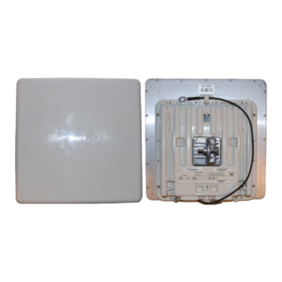
- Page 20 PTP 500 and PTP 300 Series User Guide List of Figures Figure 1 Typical bridge deployment (grounding not shown) ............1-4 Figure 2 Integrated ODU (front and rear views) ................1-7 Figure 3 Connectorized ODU (front and rear views) ..............1-7 Figure 4 ODU interfaces .........................
- Page 21 PTP 500 and PTP 300 Series User Guide Figure 32 PTP 54500 available spectrum in 5 MHz channel bandwidth ........4-11 Figure 33 PTP 58500 available spectrum in 15 MHz channel bandwidth ........4-12 Figure 34 PTP 58500 available spectrum in the 10 MHz channel bandwidth ......4-12 Figure 35 PTP 58500 available spectrum in 5 MHz channel bandwidth ........
- Page 22 List of Figures Figure 69 Webpage Properties page .................... 6-37 Figure 70 RADIUS Authentication page ..................6-38 Figure 71 Disarm Installation page (when unit is armed) ............6-41 Figure 72 Current Installation Summary page (when unit is disarmed) ........6-42 Figure 73 Step 1: Interface Configuration page ................
- Page 23 PTP 500 and PTP 300 Series User Guide Figure 106 System Status page ...................... 7-7 Figure 107 Status page - TDD enabled and synchronized ............7-13 Figure 108 Status page - TDD enabled and not synchronized ............. 7-14 Figure 109 Alarm warning triangle ....................7-15 Figure 110 Syslog local log ......................
- Page 24 PTP 500 and PTP 300 Series User Guide List of Tables Table 1 PTP 500 Series frequency variants ..................1-5 Table 2 Interpretation of existing PTP 300 and PTP 500 licenses ..........1-6 Table 3 ODU interface functions..................... 1-8 Table 4 PIDU interface functions ....................1-12 Table 5 PIDU LED functions ......................
- Page 25 PTP 500 and PTP 300 Series User Guide Table 32 Connectorized ODU physical specifications ..............4-2 Table 33 ODU environmental specifications .................. 4-2 Table 34 PIDU physical specifications .................... 4-3 Table 35 PIDU environmental specifications .................. 4-3 Table 36 PIDU electrical specifications ..................4-3 Table 37 PTP-SYNC unit physical specifications ................
- Page 26 List of Tables Table 69 Throughput: licensed 25 Mbps, link symmetry 1:1, link optimization IP (Mbps) ..4-43 Table 70 Throughput: licensed 25 Mbps, link symmetry 1:1, link optimization TDM (Mbps) ..4-44 Table 71 Throughput: licensed 105 Mbps, link symmetry = adaptive or 3:1 (Mbps) ....4-45 Table 72 Throughput: licensed 105 Mbps, link symmetry 1:1, link optimization IP (Mbps) ..
- Page 27 PTP 500 and PTP 300 Series User Guide Table 106 Email alerts........................7-19 Table 107 Spectrum Management attributes ................7-22 Table 108 Channel states represented in the spectrum management plot ......... 7-26 Table 109 Key metrics represented in the spectrum management plot ........7-26 Table 110 Channel states represented in the spectrum management plot (radar avoidance) ...
- Page 28 List of Tables phn-2511_005v000 (Mar 2013)
-
Page 29: About This User Guide
Series of point-to-point wireless Ethernet bridges. It is intended for use by the system designer, system installer and system administrator. Cambium no longer supplies the following product variants: PTP 300, PTP 500 Lite or PTP 500 Full. However, PTP 300 and PTP 500 System Releases continue to support these discontinued variants. -
Page 30: General Information
003v000 Jul 2012 System releases 500-05-02 and 300-05-02 004v000 Feb 2013 System releases 500-05-03 and 300-05-03 005v000 Mar 2013 System releases 500-05-03 and 300-05-03 (revised) Contacting Cambium Networks Support website: http://www.cambiumnetworks.com/support Main website: http://www.cambiumnetworks.com Sales enquiries: solutions@cambiumnetworks.com Support enquiries: support@cambiumnetworks.com Telephone number list: http://www.cambiumnetworks.com/contact.php... - Page 31 It is recommended that all personnel engaged in such activities be properly trained. Cambium disclaims all liability whatsoever, implied or express, for any risk of damage, loss or reduction in system performance arising directly or indirectly out of the failure of the customer, or anyone acting on the customer's behalf, to abide by the instructions, system parameters, or recommendations made in this document.
-
Page 32: Problems And Warranty
Warranty Cambium’s standard hardware warranty is for one (1) year from date of shipment from Cambium or a Cambium distributor. Cambium warrants that hardware will conform to the relevant published specifications and will be free from material defects in material and workmanship under normal use and service. - Page 33 PTP 500 and PTP 300 Series User Guide Problems and warranty Portions of Cambium equipment may be damaged from exposure to electrostatic discharge. Use precautions to prevent damage. phn-2511_005v000 (Mar 2013)
-
Page 34: Security Advice
Security advice About This User Guide Security advice Cambium Networks systems and equipment provide security parameters that can be configured by the operator based on their particular operating environment. Cambium recommends setting and using these parameters following industry recognized security practices. -
Page 35: Warnings, Cautions, And Notes
Warnings, cautions, and notes Warnings, cautions, and notes The following describes how warnings and cautions are used in this document and in all documents of the Cambium Networks document set. Warnings Warnings precede instructions that contain potentially hazardous situations. Warnings are used to alert the reader to possible hazards that could cause loss of life or physical injury. -
Page 36: Caring For The Environment
Disposal of Cambium equipment European Union (EU) Directive 2002/96/EC Waste Electrical and Electronic Equipment (WEEE) Do not dispose of Cambium equipment in landfill sites. For disposal instructions, refer to http://www.cambiumnetworks.com/doc.php. Disposal of surplus packaging Do not dispose of surplus packaging in landfill sites. In the EU, it is the individual recipient’s responsibility to ensure that packaging materials are collected and recycled... -
Page 37: Chapter 1: Product Description
PTP 500 and PTP 300 Series User Guide Chapter 1: Product description This chapter provides a high level description of the PTP 500 product. It describes in general terms the function of the product, the main product variants and typical deployment. -
Page 38: Overview Of The Ptp 500
PTP 500. Purpose Cambium PTP 500 Series products are designed for Ethernet bridging over point-to-point microwave links in the unlicensed bands 5.4 GHz (ETSI Band B) and 5.8 GHz (ETSI Band C and FCC ISM band). Users must ensure that the links comply with local operating regulations. -
Page 39: Typical Deployment
Typical deployment The PTP 500 Series bridge consists of an identical pair of units deployed one at each end of the link. The radio link operates on a single frequency channel in each direction using Time Division Duplex (TDD). -
Page 40: System Components
Overview of the PTP 500 Chapter 1: Product description Figure 1 Typical bridge deployment (grounding not shown) System components Each end of the link consists of: • Outdoor Unit (ODU): An integrated (or connectorized) outdoor transceiver unit containing all the radio and networking electronics. •... -
Page 41: Product Variants
PTP 500 and PTP 300 Series User Guide Overview of the PTP 500 Product variants The PTP 500 Series is available in the following product variants: • Frequency variants: There is a frequency variant for each license exempt frequency band 5.4 GHz and 5.8 GHz (Table 1). -
Page 42: Support For Discontinued Product Variants
Overview of the PTP 500 Chapter 1: Product description Support for discontinued product variants Cambium no longer supplies the following product variants: • PTP 300 • PTP 500 Lite • PTP 500 Full However, PTP 300 and PTP 500 System Releases continue to support these discontinued variants. -
Page 43: Outdoor Unit (Odu)
PTP 500 and PTP 300 Series User Guide Outdoor unit (ODU) Outdoor unit (ODU) This section describes the PTP 500 ODU and its interfaces. ODU description The ODU is a self-contained unit that houses both radio and networking electronics. The ODU is supplied in two configurations: integrated (attached to its own flat plate antenna, Figure 2) or connectorized (without an antenna,... -
Page 44: Odu Interfaces
Outdoor unit (ODU) Chapter 1: Product description Connectorized variant The connectorized ODU is designed to work with externally mounted antennas that have higher gains than the integrated antenna. Connectorized units can cope with more difficult radio conditions, as described in When to install connectorized units on page 2-15. -
Page 45: Connectorized Odu Antenna Interfaces
PTP 500 and PTP 300 Series User Guide Outdoor unit (ODU) Connectorized ODU antenna interfaces The connectorized ODU also has interfaces to connect to an external antenna (Figure via an N type connector with cable of type LMR100, LMR200, LMR300, LMR400 or LMR600. -
Page 46: Further Reading On The Odu
PTP 500 installation, including the ODU. • Ordering components on page 2-46 lists the components required for PTP 500 installations, including ODUs, with Cambium part numbers. • FCC and IC approved antennas on page 2-53 contains specifications of the antennas that may be used with connectorized ODUs. -
Page 47: Powered Indoor Unit (Pidu)
PTP 500 and PTP 300 Series User Guide Powered indoor unit (PIDU) Powered indoor unit (PIDU) This section describes the PIDU Plus PTP 300/500/600 Series and its interfaces. PIDU description The PIDU generates the ODU supply voltage from the mains supply (or from an external DC source) and injects this supply voltage into the ODU. -
Page 48: Table 4 Pidu Interface Functions
Powered indoor unit (PIDU) Chapter 1: Product description Table 4 PIDU interface functions Interface Function 100-240 V ac Mains power input. 47-63Hz 1.8A DC In Alternative DC power supply input. Refer to Redundancy and alternative powering configurations on page 1-13. DC Out DC power output to a second PIDU. -
Page 49: Redundancy And Alternative Powering Configurations
PTP 500 and PTP 300 Series User Guide Powered indoor unit (PIDU) Redundancy and alternative powering configurations The PTP 500 Series can be powered from an external DC source and can be provided with power supply redundancy as follows: •... -
Page 50: Remote Leds And Recovery Switch
Powered indoor unit (PIDU) Chapter 1: Product description Figure 9 External DC supply and redundant AC supply Remote LEDs and recovery switch The PIDU provides a facility to connect remote LEDs and Recovery switch allowing the PIDU to be mounted inside an enclosure. At the left hand end of the PIDU under the ODU connection cover can be found a PCB header and three jumpers. -
Page 51: Further Reading On The Pidu
PIDU. • Ordering components on page 2-46 lists the components required for PTP 500 installations, including PIDU units, with Cambium part numbers. • PIDU specifications on page contains specifications of the PIDU such as dimensions, weight, environmental and electrical requirements. -
Page 52: Cabling And Lightning Protection
Cabling and lightning protection Chapter 1: Product description Cabling and lightning protection This section describes the cabling and lightning protection components of PTP 500 installations. PTP and lightning protection The PIDU meets the low level static discharge specifications identified in Electromagnetic compatibility (EMC) compliance on page... -
Page 53: Indoor Connections
PTP 500 and PTP 300 Series User Guide Cabling and lightning protection Indoor connections The Cat5e cable that connects the PIDU to the network equipment must meet the following requirements: • Screening: Must be either foil screen (FTP) or braided screen (STP) cable. •... -
Page 54: Lightning Protection Units (Lpus)
Cabling and lightning protection Chapter 1: Product description Lightning protection units (LPUs) One LPU single end kit (Figure 12) is required for each ODU drop cable. If GPS is installed (for PTP-SYNC), one additional LPU kit is required for the GPS drop cable. The LPU is installed near the point at which the drop cable enters the building. -
Page 55: Ptp-Sync Unit
PTP 500 and PTP 300 Series User Guide PTP-SYNC unit PTP-SYNC unit This section describes the (optional) PTP-SYNC unit and its interfaces. This unit may be used to implement TDD synchronization. PTP-SYNC unit description The PTP-SYNC unit (Figure 13) is an optional component. It is required when TDD synchronization is implemented using PTP-SYNC. -
Page 56: Ptp-Sync Unit Interfaces
Input from GPS receiver or from the daisy-chained SYNC OUT signal of another PTP-SYNC. SYNC OUT Output to daisy-chained PTP-SYNC units. UPGRADE Input for software upgrades. Contact Cambium for instructions. 1PPS IN Coaxial alternative to GPS/SYNC IN. Peak input voltage must not exceed 5 V. -
Page 57: Further Reading On Ptp-Sync
• Ordering components on page 2-46 lists the components required for PTP 500 installations, including PTP-SYNC and GPS units, with Cambium part numbers. • PTP-SYNC specifications on page contains specifications of the PTP-SYNC unit that is supplied by Cambium for PTP 500 installations. -
Page 58: Wireless Operation
Wireless operation Chapter 1: Product description Wireless operation This section describes how PTP 500 wireless links are operated, including modulation modes, power control and security. Time division duplexing TDD cycle PTP 500 links operate using Time Division Duplexing (TDD). They use a TDD cycle in which the ODUs alternately transmit and receive TDD bursts. -
Page 59: Figure 15 Tdd Cycle
Figure 15 TDD cycle Channel selection The PTP 500 Series links are capable of transmitting and receiving on the same channel or on different channels. In other words, the slave-master direction may use a different channel from the master-slave direction. Independent selection of transmit and receive frequencies can be useful in planned networks or for countering interference. -
Page 60: Link Mode Optimization
(for example voice over IP data). TDM mode is selected automatically when Telecom interfaces are enabled. Link symmetry The PTP 500 Series provides four configuration options for apportioning the available capacity between the two link directions. • Symmetric: The Master and Slave have equal capacity. The system achieves this by allocating an equal Burst Duration for the Master and the Slave. -
Page 61: Ofdm And Channel Bandwidth
PTP 500 and PTP 300 Series User Guide Wireless operation • Adaptive: The capacity allocated to a given link direction is dependent on the offered level of network traffic in both link directions. If the level of offered traffic in both directions is equally high or equally low, the system will allocate equal capacity to both directions. -
Page 62: Spectrum Management Measurements
Wireless operation Chapter 1: Product description Spectrum management measurements The system performs two mean signal measurements per TDD cycle, per channel. This mean measurement represents the mean received signal power for the measurement period (40 microseconds). The Spectrum Management algorithm collects measurements equally from all channels. This process is called the Channel Availability Check (hereafter referred to by the acronym CAC). -
Page 63: Adaptive Modulation
PTP 500 and PTP 300 Series User Guide Wireless operation Fixed frequency mode is not available in regions where radar detection is required by the regulations. Adaptive modulation The PTP 500 can transport data over the wireless link using a number of different modulation modes ranging from 64QAM 0.83 to BPSK 0.50. -
Page 64: Dynamic Spectrum Optimization
Wireless operation Chapter 1: Product description • Single Payload: As the radio channel becomes more challenging, the system has the ability to detect this and switch to a mode which transmits the same data stream on both vertical and horizontal channels. This provides polar diversity and is another key feature which allows the system to operate in challenging non- line of sight radio channels. -
Page 65: Security
PTP 500 and PTP 300 Series User Guide Wireless operation • This compulsory channel scan will mean that there is at least 60 seconds service outage every time radar is detected and that the installation time is extended by at least 60 seconds even if there is found to be no radar on the channel •... -
Page 66: Ptp Networks
Using several different channels • Separating units located on the same mast • Using high performance (directional) external antennas For help with planning networks, refer to Chapter 2: Planning considerations, or contact your Cambium distributor or re-seller. phn-2511_005v000 (Mar 2013) 1-30... -
Page 67: Tdd Synchronization
PTP 500 and PTP 300 Series User Guide Wireless operation Synchronized networks TDD synchronization can be used to relax constraints on the frequency planning of PTP 500 networks. Synchronization has the following benefits: • Allows tighter frequency re-use, and thus wider channel bandwidth. •... - Page 68 Wireless operation Chapter 1: Product description Timing references for use with PTP-SYNC PTP-SYNC requires an external timing reference in all but the simplest networks. Up to ten PTP-SYNCs can be connected in a chain to share the timing signal from one timing reference.
-
Page 69: Further Reading On Wireless Operation
PTP 500 and PTP 300 Series User Guide Wireless operation • The GPS receiver can be located anywhere with a clear view of the sky, offering additional flexibility in the installation. • The PTP-SYNC solution is compatible with standard 1 Hz interfaces, allowing an operator to take advantage of alternative timing references that may be already present at the site. -
Page 70: Ethernet Bridging
Ethernet bridging Chapter 1: Product description Ethernet bridging This section describes how the PTP 500 controls Ethernet data, in both the customer and system management networks. Customer network Transparent Ethernet service The PTP 500 provides an Ethernet service between the Ethernet port at a local ODU and the Ethernet port at an associated remote ODU. -
Page 71: Management Network
PTP 500 and PTP 300 Series User Guide Ethernet bridging Quality of service for bridged Ethernet traffic The PTP 500 supports eight traffic classes for Ethernet frames queued for transmission over the wireless link. Ethernet frames are classified by inspection of the Ethernet priority code point in the outermost VLAN tag. -
Page 72: Back-To-Back Links
Ethernet bridging Chapter 1: Product description In-band management In the in-band management mode, the management agent can be reached from the Ethernet port at the local ODU, and (assuming that the wireless link is established) the Ethernet port at the remote ODU. Management frames in the customer network are processed by the management agent if (a) destination MAC address in the frame matches the CMU MAC address, and (b) the VLAN ID in the frame matches the VLAN configuration of the management agent. -
Page 73: Protocol Model
PTP 500 and PTP 300 Series User Guide Ethernet bridging Protocol model Ethernet bridging behavior at each end of the wireless link is equivalent to a two-port, managed, transparent MAC bridge where the two ports are: • Ethernet Port • Wireless Port Frames are transmitted at the Wireless port over a proprietary point-to-point circuit-mode link layer between ends of the link. -
Page 74: Further Reading On Ethernet Bridging
Ethernet bridging Chapter 1: Product description Figure 17 Protocol layers between external interfaces and the management agent Further reading on Ethernet bridging For more information on Ethernet bridging, refer to the following: • Data network planning on page 2-35 describes factors to be considered when planning PTP 500 data networks. - Page 75 PTP 500 and PTP 300 Series User Guide Ethernet bridging • Reviewing system configuration attributes on page 6-87 describes how to review the IP and Ethernet attributes of the PTP 500. phn-2511_005v000 (Mar 2013) 1-39...
-
Page 76: Telecoms Circuits
Telecoms circuits Chapter 1: Product description Telecoms circuits This section describes how telecoms traffic (E1 or T1) may be carried over PTP 500 links. PTP 500 does not allow TDD synchronization to be enabled when telecoms (E1 or T1) is enabled. -
Page 77: Further Reading On Telecoms Circuits
PTP 500 and PTP 300 Series User Guide Telecoms circuits Fixed frequency operation is not available when radar detection requirements exist in the frequency band. Channel barring is allowed in radar regions, but it is unwise to bar all channels except one, as any radar signals detected on that channel will drop the link for up to 30 minutes. -
Page 78: System Management
System management Chapter 1: Product description System management This section introduces the PTP 500 management system, including the web interface, installation, configuration, alerts and upgrades. Management agent PTP 500 equipment is managed through an embedded management agent. Management workstations, network management systems or PCs can be connected to this agent using standard management protocols multiplexed with user traffic at the Ethernet data port. -
Page 79: Web Pages
Details of the security material needed for HTTPS/TLS are provided in Security planning on page 2-37. The PTP 500 has no default public key certificate, and Cambium is not able to generate private keys or public key certificates for specific network applications. phn-2511_005v000 (Mar 2013) -
Page 80: User Account Management
System management Chapter 1: Product description User account management PTP 500 allows a network operator to configure a policy for login attempts, the period of validity of passwords and the action taken on expiry of passwords. See Configuring local user accounts on page 6-30 for further details. -
Page 81: Radius Authentication
PTP 500 and PTP 300 Series User Guide System management RADIUS authentication PTP 500 supports remote authentication for users of the web interface using the Remote Authentication Dial-In User Service (RADIUS) with one of the following authentication methods: • Challenge-Handshake Authentication Protocol (CHAP). •... -
Page 82: Snmp Engine Id
System management Chapter 1: Product description • PTP 500 Series proprietary MIB. Simple Network Time Protocol (SNTP) The clock supplies accurate date and time information to the system. It can be set to run with or without a connection to a network time server (SNTP). It can be configured to display local time by setting the time zone and daylight saving in the Time web page. - Page 83 PTP 500 and PTP 300 Series User Guide System management View-based access control model PTP 500 supports the SNMPv3 view-based access control model (VACM) with a single context. The context name is the empty string. The context table is read-only, and cannot be modified by users.
- Page 84 System management Chapter 1: Product description The default user is created with a view of the entire MIB, requiring authentication initial for SET operations. There is no access for template users. VACM grants access for requests sent with more than the configured security level. The default user will have read/write access to the whole of the MIB.
-
Page 85: System Logging (Syslog)
PTP 500 and PTP 300 Series User Guide System management • SNMPv3 Security Management is changed from MIB-based to web-based. Additionally, all SNMP user accounts are disabled when the authentication protocol, the privacy protocol, or the security level is changed. Downgrade of the license key A possible lockout condition exists if a user downgrades the license key so as to disable the AES capability when SNMPv3 users are configured with AES privacy and VACM is... -
Page 86: Aes License
PTP 500 provides optional encryption using the Advanced Encryption Standard (AES). Encryption is not available in the standard system. AES upgrades are supplied as an access key purchased from your Cambium Point-to-Point distributor or solutions provider. The access key authorizes AES operation for one ODU. -
Page 87: Critical Security Parameters
• From 25 Mbps to 105 Mbps A capacity upgrade is supplied as an access key purchased from your Cambium Point-to- Point distributor or solutions provider. The upgrade is applied by entering an access key together with the MAC address of the target ODU into the PTP License Key Generator web... -
Page 88: Software Upgrade
SNMP interface. PTP 500 software images are digitally signed, and the ODU will accept only images that contain a valid Cambium PTP digital signature. The ODU always requires a reboot to complete a software upgrade. Obtain the application software and this user guide from the support website BEFORE warranty expires. -
Page 89: Further Reading On System Management
PTP 500 and PTP 300 Series User Guide System management • When a checksum error occurs for the main application software image. • When the PIDU recovery button is pressed at the same time as the ODU is rebooted or power cycled. - Page 90 System management Chapter 1: Product description phn-2511_005v000 (Mar 2013) 1-54...
-
Page 91: Chapter 2: Planning Considerations
PTP 500 links to operate in secure mode. • Ordering components on page 2-46 describes how to select components for a planned PTP 500 link (as an alternative to PTP LINKPlanner). It specifies Cambium part numbers for PTP 500 components. phn-2511_005v000 (Mar 2013) -
Page 92: Regulatory Planning
Examples of regulatory limits on page 4-31. Many countries impose EIRP limits (Allowed EIRP) on products operating in the bands used by the PTP 500 Series. For example, in the 5.4 GHz and 5.8 GHz bands, these limits are calculated as follows: •... -
Page 93: Available Spectrum
PTP 500 and PTP 300 Series User Guide Regulatory planning • When installing 5.4 GHz links in the USA, it may be necessary to avoid frequencies used by Terminal Doppler Weather Radar (TDWR) systems. For more information, refer Avoidance of weather radars (USA only) on page 2-5. -
Page 94: Channel Bandwidth
Regulatory planning Chapter 2: Planning considerations Channel bandwidth Select the required channel bandwidth for the link. The selection depends upon the frequency variant and region code, as specified in Examples of regulatory limits on page The wider the channel bandwidth, the greater the capacity. As narrower channel bandwidths take up less spectrum, selecting a narrow channel bandwidth may be a better choice when operating in locations where the spectrum is very busy. -
Page 95: Avoidance Of Weather Radars (Usa Only)
PTP 500 and PTP 300 Series User Guide Regulatory planning • DFS with DSO: In addition to switching channels on detection of radar, the unit will also switch to a channel which has a significantly lower level of interference than the current channel of operation. -
Page 96: Site Planning
Site planning Chapter 2: Planning considerations Site planning This section describes factors to be taken into account when choosing sites for the ODU, PIDU and PTP-SYNC unit (if installed). ODU site selection When selecting a site for the ODU, consider the following factors: •... -
Page 97: Maximum Cable Lengths
PTP 500 and PTP 300 Series User Guide Site planning Maximum cable lengths When PTP-SYNC is not installed, the maximum permitted length of the copper Ethernet interface cable is 100 m (330 ft) from ODU to network terminating equipment. When PTP-SYNC is installed, the maximum permitted lengths of each section of the copper Ethernet interface cable are as specified in (Figure 18). -
Page 98: Wind Loading
Site planning Chapter 2: Planning considerations Wind loading Ensure that the site will not be prone to excessive wind loading. Antennas and equipment mounted on towers or buildings will subject the mounting structure to significant lateral forces when there is appreciable wind. Antennas are normally specified by the amount of force (in pounds) for specific wind strengths. -
Page 99: Table 9 Lateral Force - Us
Capabilities of the PTP 500 Series The structure and mounting brackets of the ODU are capable of withstanding wind speeds up to 242 kph (151 mph). Ensure that the structure to which the ODU is fixed to is also capable of withstanding the prevalent wind speeds and loads. -
Page 100: Link Planning
This section describes factors to be taken into account when planning links, such as range, obstacles path loss and throughput. PTP LINKPlanner is recommended. PTP LINKPlanner Cambium Networks provide a free tool to help plan your PTP links. Download your copy of LinkPlanner from the support website (see Contacting Cambium Networks on page 2). -
Page 101: Ptp Linkplanner For Synchronized Networks
PTP 500 and PTP 300 Series User Guide Link planning LoS links in radar regions When planning an LoS link to operate in a radar detection region, ensure that receiver signal level is low enough to allow the PTP 500 to detect radar signals: •... -
Page 102: Table 10 Parameters That Influence Modulation Mode Selection
Link planning Chapter 2: Planning considerations Adaptive modulation Adaptive modulation ensures that the highest throughput that can be achieved instantaneously will be obtained, taking account of propagation and interference. When the link has been installed, web pages provide information about the link loss currently measured by the equipment, both instantaneously and averaged. -
Page 103: System Threshold, Output Power And Link Loss
PTP 500 and PTP 300 Series User Guide Link planning System threshold, output power and link loss For details of the system threshold, output power and link loss for each frequency variant in all modulation modes for all available channel bandwidths, refer to System threshold, output power and link loss on page 4-14. - Page 104 Link planning Chapter 2: Planning considerations Calculation example Suppose that the link characteristics are: • Licensed capacity = 105 Mbps • Link Symmetry = 1:1 • Link Mode Optimization = TDM • Modulation Mode = 64QAM 0.83 Dual • Channel Bandwidth = 10 MHz •...
-
Page 105: Planning For Connectorized Units
PTP 500 and PTP 300 Series User Guide Planning for connectorized units Planning for connectorized units This section describes factors to be taken into account when planning to use connectorized ODUs with external antennas in PTP 500 links. When to install connectorized units The majority of radio links can be successfully deployed with the integrated PTP 500. -
Page 106: Calculating Maximum Power Level For Connectorized Units
Planning for connectorized units Chapter 2: Planning considerations Under Industry Canada regulations, this radio transmitter may only operate using an antenna of a type and maximum (or lesser) gain approved for the transmitter by Industry Canada. To reduce potential radio interference to other users, the antenna type and its gain should be so chosen that the equivalent isotropically radiated power (EIRP) is not more than that necessary for successful communication. -
Page 107: Table 11 Normal Eirp Limits With Operating Channel Bandwidth
0.5 dB cable loss and the highest gain antennas per size of which Cambium are aware. At these operating frequencies, feeder losses even with short cables are unlikely ever to be below 0.5 dB for practical installations and cable diameters. -
Page 108: Calculating Rf Cable Length (5.8 Ghz Fcc Only)
Planning for connectorized units Chapter 2: Planning considerations Antenna Gain and Cable Loss must be entered correctly in the Installation Wizard, as they are used by the software to impose an automatic constaint on Maximum Power Level. For more information, see Step 2: Wireless configuration on page 6-46. -
Page 109: Grounding And Lightning Protection
The actual degree of protection required depends on local conditions and applicable local regulations. Cambium recommends that PTP 500 installation is contracted to a professional installer. -
Page 110: Lightning Protection Zones
Grounding and lightning protection Chapter 2: Planning considerations Lightning protection zones The ‘rolling sphere method’ (Figure 19) is used to determine where it is safe to mount equipment. An imaginary sphere, typically 50 meters in radius, is rolled over the structure. -
Page 111: Basic Requirements
PTP 500 and PTP 300 Series User Guide Grounding and lightning protection General protection requirements To adequately protect a PTP 500 installation, both ground bonding and transient voltage surge suppression are required. Basic requirements The following basic protection requirements must be implemented: •... -
Page 112: Protection Requirements For A Mast Or Tower Installation
Grounding and lightning protection Chapter 2: Planning considerations Figure 20 Grounding cable minimum bend radius and angle Protection requirements for a mast or tower installation If the ODU is to be mounted on a metal tower or mast, then in addition to the general protection requirements (above), the following requirements must be observed: •... -
Page 113: Figure 21 Grounding And Lightning Protection On Mast Or Tower
PTP 500 and PTP 300 Series User Guide Grounding and lightning protection Figure 21 Grounding and lightning protection on mast or tower phn-2511_005v000 (Mar 2013) 2-23... -
Page 114: Protection Requirements For A Wall Installation
Grounding and lightning protection Chapter 2: Planning considerations Protection requirements for a wall installation If the ODU is to be mounted on the wall of a building, then in addition to the general protection requirements (above), the following requirements must be observed: •... -
Page 115: Protection Requirements On A High Rise Building
PTP 500 and PTP 300 Series User Guide Grounding and lightning protection Protection requirements on a high rise building If the ODU is to be mounted on a high rise building, it is likely that cable entry is at roof level (Figure 23) and the equipment room is several floors below... -
Page 116: Figure 23 Grounding And Lightning Protection On Building
Grounding and lightning protection Chapter 2: Planning considerations Figure 23 Grounding and lightning protection on building phn-2511_005v000 (Mar 2013) 2-26... -
Page 117: Figure 24 Grounding And Lightning Protection Inside High Building
PTP 500 and PTP 300 Series User Guide Grounding and lightning protection Protection inside a high rise building The following protection requirements must be observed inside multi-story or high rise buildings (Figure 24): • The drop cable shield must be bonded to the building grounding system at the entry point to the building. -
Page 118: Configuration Options For Tdd Synchronization
Configuration options for TDD synchronization Chapter 2: Planning considerations Configuration options for TDD synchronization This section describes the different configuration options that may be used for implementing TDD synchronization in the PTP 500. Schematic diagrams are included. The PTP 500 supports the following TDD synchronization configurations: •... -
Page 119: Cluster With Ptp-Sync And Gps Receiver
PTP 500 and PTP 300 Series User Guide Configuration options for TDD synchronization Figure 25 TDD synchronization configuration – single link with PTP-SYNC Cluster with PTP-SYNC and GPS receiver Each link requires one PTP-SYNC unit. Each site requires one compatible GPS receiver. Collocated PTP-SYNC units are connected together in a daisy-chain. -
Page 120: Cluster With Ptp-Sync And No Gps Receiver
Configuration options for TDD synchronization Chapter 2: Planning considerations Figure 26 TDD synchronization configuration – cluster with PTP-SYNC and GPS Cluster with PTP-SYNC and no GPS receiver Each link requires one PTP-SYNC unit. PTP-SYNC units are connected together in a daisy- chain. -
Page 121: Figure 27 Tdd Synchronization Configuration - Cluster With Ptp-Sync And No Gps
PTP 500 and PTP 300 Series User Guide Configuration options for TDD synchronization Figure 27 TDD synchronization configuration – cluster with PTP-SYNC and no GPS phn-2511_005v000 (Mar 2013) 2-31... -
Page 122: Mounting Options For The Ptp-Sync Gps Receiver
Mounting options for the PTP-SYNC GPS receiver Chapter 2: Planning considerations Mounting options for the PTP-SYNC GPS receiver This section describes the requirements of the (optional) GPS receiver for PTP-SYNC. If PTP-SYNC is to be installed with a GPS receiver as the timing reference source, then the GPS receiver must be mounted as described in this section. -
Page 123: Figure 28 Grounding And Lightning Protection For Gps Receiver On Building
PTP 500 and PTP 300 Series User Guide Mounting options for the PTP-SYNC GPS receiver Figure 28 Grounding and lightning protection for GPS receiver on building phn-2511_005v000 (Mar 2013) 2-33... -
Page 124: Mounting The Gps Receiver Module On A Metal Tower Or Mast
Mounting options for the PTP-SYNC GPS receiver Chapter 2: Planning considerations Mounting the GPS receiver module on a metal tower or mast If mounting the GPS receiver module on a metal tower or mast (Figure 29), select a position that meets the following requirements: •... -
Page 125: Data Network Planning
PTP 500 and PTP 300 Series User Guide Data network planning Data network planning This section describes factors to be considered when planning PTP 500 data networks. VLAN membership Decide if the IP interface of the ODU management agent will be connected in a VLAN. If so, decide if this is a standard (IEEE 802.1Q) VLAN or provider bridged (IEEE 802.1ad) VLAN, and select the VLAN ID for this VLAN. -
Page 126: Back To Back Links
Data network planning Chapter 2: Planning considerations Ethernet priority information is coded in the Ethernet VLAN tag and differentiated quality of service is therefore not available in a network based on untagged Ethernet frames. Back to back links Avoid the use of direct cabled connections between two PIDUs. Where two or more links are deployed in a chain, always use an Ethernet switch or router to interconnect the links at a relay point. -
Page 127: Security Planning
PTP 500 and PTP 300 Series User Guide Security planning Security planning This section describes how to plan for PTP 500 links to operate in secure mode. Planning for SNTP operation Before starting to configure Simple Network Time Protocol (SNTP): •... -
Page 128: Supported Mibs
Security planning Chapter 2: Planning considerations Item Description Quantity required User Defined Security notices to users of the system. Use text Normally one per link. Security that is appropriate to the network security policy. This depends upon Banner network policy. Entropy Input This must be of size 512 bits (128 hexadecimal Two per link. - Page 129 RFC-3826. SNMP-USM-AES-MIB • RFC-4293 IP-MIB • PTP 500 Series proprietary MIBs The proprietary MIBs are provided in the PTP 500 Series software download files in the support webpage (see Contacting Cambium Networks on page 2). Supported alarms PTP 500 supports the following diagnostic alarms: •...
-
Page 130: Enabling Snmp
Security planning Chapter 2: Planning considerations The web-based interface may be used to enable or disable generation of each supported SNMP notification or diagnostic alarm. Enabling SNMP Enable the SNMP interface for use by configuring the following attributes in the Remote Management page: •... - Page 131 PTP 500 and PTP 300 Series User Guide Security planning Web-based management of SNMPv3 security Initial configuration of SNMPv3 security is available only to HTTP or HTTPS/TLS user accounts with security role of Security Officer. Identify the minimum security role of HTTP or HTTPS/TLS user accounts that will be permitted access for web-based management of SNMPv3 security.
-
Page 132: Table 15 Permitted Character Set For Snmpv3 Passphrases
Security planning Chapter 2: Planning considerations If authentication or authentication and privacy protocols are required, identify passphrases for each protocol for each SNMP user. It is considered good practice to use different passphrases for authentication and privacy. Passphrases must have length between 8 and 32 characters, and may contain any of the characters listed in Table Table 15 Permitted character set for SNMPv3 passphrases... -
Page 133: Table 16 Default Snmpv3 Users
PTP 500 and PTP 300 Series User Guide Security planning SNMPv3 default configuration (MIB-based) When SNMPv3 MIB-based Security Mode is enabled, the default configuration for the table is based on one initial user and four template users as listed in Table usmUserTable Table 16 Default SNMPv3 users... -
Page 134: Radius Attributes
Security planning Chapter 2: Planning considerations Planning for RADIUS operation Configure RADIUS where remote authentication is required for users of the web-based interface. Remote authentication has the following advantages: • Control of passwords can be centralized. • Management of user accounts can be more sophisticated For example, users can be prompted by email to change passwords at regular intervals. -
Page 135: Table 17 Definition Of Auth-Role Vendor Specific Attributes
PTP 500 and PTP 300 Series User Guide Security planning If the vendor-specific auth-role attribute is absent, but the standard service-type (Type 6) attribute is present, PTP 500 selects the role for the authenticated user according to service-type. The supported values of service-type are as follows: •... -
Page 136: Ordering Components
Chapter 2: Planning considerations Ordering components This section describes describes how to select components for a planned PTP 500 link (as an alternative to PTP LINKPlanner). It specifies Cambium part numbers for PTP 500 components. PTP 500 kits The PTP 500 is supplied as a “Link Complete” or an “End Complete” kit. A Link Complete kit contains components for both ends of a link (including two ODUs and two PIDU units). -
Page 137: Table 19 Ptp 54500 Kit Part Numbers
PTP 500 and PTP 300 Series User Guide Ordering components Frequency band Region Regional variant 5.8 GHz Eire ETSI/RoW 5.8 GHz FCC USA, Canada, Taiwan, Brazil FCC/IC 5.8 GHz Full Power ETSI/RoW 5.8 GHz Full Power + Radar + RTTT ETSI/RoW 5.8 GHz Germany... -
Page 138: Table 20 Ptp 58500 Kit Part Numbers
Ordering components Chapter 2: Planning considerations Table 20 PTP 58500 kit part numbers Frequency Regional Integrated or Link or Part variant variant Connectorized End Complete number PTP 58500 ETSI/RoW Integrated Link Complete C058050B005 PTP 58500 ETSI/RoW Integrated End Complete C058050B006 PTP 58500 ETSI/RoW Connectorized... - Page 139 PTP 500 and PTP 300 Series User Guide Ordering components Item Notes PIDU End Complete kit contains one PIDU unit. Link Complete kit contains two PIDU units. Mounting bracket assembly End Complete kit contains one bracket. Link Complete kit contains two brackets. Choice of mains leads (US, UK and EU) End Complete kit contains one US, one UK and one EU lead.
-
Page 140: Other Standard Components
Table 22 Additional inventory for standard installations Item Notes Outdoor drop cable Superior Essex BBDGe cable is supplied by Cambium with the following lengths and part numbers (other lengths are available from Superior Essex): ‘1000 ft Reel Outdoor Copper Clad CAT5E’. Cambium part number Always use Cat5e cable that is gel-filled WB3175. - Page 141 Notes Cable grounding kits One kit is required per drop cable grounding point. ‘Cable Grounding Kits For 1/4" And 3/8" Cable’. Cambium part number 01010419001. Kit contents: grounding cable, self- amalgamating tape, PVC tape, tie- wraps, bolts, washers and nuts.
-
Page 142: Components Required With Connectorized Odus
For connecting the ODU to the antenna. May be cable of type LMR100, LMR200, LMR300, LMR400 or LMR600. LMR400 is supplied by Cambium: ‘50 Ohm Braided Coaxial Cable - 75 meter’. Cambium part number 30010194001. ‘50 Ohm Braided Coaxial Cable - 500 meter’. Cambium part number 30010195001. - Page 143 ‘RF CONNECTOR,N,MALE,STRAIGHT FOR CNT-400 CABLE’. Cambium part number 09010091001. For the antenna end of the RF cable, refer to the antenna manufacturer’s instructions.
-
Page 144: Table 24 Allowed Antennas For Deployment In Usa/Canada - 5.4 Ghz
Ordering components Chapter 2: Planning considerations This radio transmitter ( IC certification number 109AO-5X250 ) has been approved by Industry Canada to operate with the antenna types listed below with the maximum permissible gain and required antenna impedance for each antenna type indicated. Antenna types not included in this list, having a gain greater than the maximum gain indicated for that type, are strictly prohibited for use with this device. - Page 145 PTP 500 and PTP 300 Series User Guide Ordering components Manufacturer Antenna Type Gain Parabolic (dBi) Dish Gabriel Gabriel 4-foot Standard QuickFire Parabolic, 34.8 QF4-52-N Gabriel Gabriel 4-foot Standard QuickFire Parabolic, 34.8 QF4-52-N-RK Gabriel Gabriel 2-foot Standard Dual QuickFire 28.4 Parabolic, QFD2-52-N Gabriel Gabriel 2.5-foot Standard Dual QuickFire...
-
Page 146: Table 25 Allowed Antennas For Deployment In Usa/Canada - 5.8 Ghz
Ordering components Chapter 2: Planning considerations Manufacturer Antenna Type Gain Parabolic (dBi) Dish RFS 4-foot HP Parabolic, SDF4-52AN or SDFX4- 33.9 52AN (33.9 dBi) Table 25 Allowed antennas for deployment in USA/Canada – 5.8 GHz Manufacturer Antenna Type Gain Flat Parabolic (dBi) Plate... - Page 147 PTP 500 and PTP 300 Series User Guide Ordering components Manufacturer Antenna Type Gain Flat Parabolic (dBi) Plate Dish Gabriel Gabriel 2-foot Standard QuickFire 28.5 Parabolic, QF2-52-N Gabriel Gabriel 2-foot Standard QuickFire 28.5 Parabolic, QF2-52-N-RK Gabriel Gabriel 2.5-foot Standard QuickFire 31.2 Parabolic, QF2.5-52-N Gabriel...
- Page 148 Ordering components Chapter 2: Planning considerations Manufacturer Antenna Type Gain Flat Parabolic (dBi) Plate Dish RadioWaves Radio Waves 3-foot Parabolic, SP3- 31.4 5.2 (31.4 dBi) RadioWaves Radio Waves 4-foot Dual-Pol 34.4 Parabolic, SPD4-5.2 (34.4 dBi) RadioWaves Radio Waves 4-foot Parabolic, SP4- 34.8 5.2 (34.8 dBi) RadioWaves...
-
Page 149: Table 26 Sectored Antennas For Deployment In Usa/Canada - 5.8 Ghz
PTP 500 and PTP 300 Series User Guide Ordering components Table 26 Sectored antennas for deployment in USA/Canada – 5.8 GHz Manufacturer Antenna Type Gain Beamwidth (dBi) RadioWaves SEC-55V-60-17 60° SEC-55H-60-17 SEC-55D-60-17 RadioWaves SEC-55V-90-16 90° SEC-55H-90-16 SEC-55D-90-16 phn-2511_005v000 (Mar 2013) 2-59... -
Page 150: Ptp-Sync Installations
1 x Cat5e cable (length 1 meter) Installation guide PTP-SYNC rack mount Required for rack-mounted PTP-SYNC units. ‘PTP800 CMU / PTP-SYNC 19” rack mount installation kit’. Cambium part number WB3486. Kit contents: 1 x rack bracket 8 x M3 washers 8 x M3 screws... -
Page 151: Gps Receiver Installations
Table 28 Additional inventory for GPS receiver installations Item Notes GPS receiver ‘Trimble Acutime™Gold GPS receiver’. Cambium part number WB3903. GPS adapter cable kit (optional) Avoids the need to fit a 12 way circular connector to the GPS drop cable. ‘PTP-SYNC <-> Trimble Adapter Cable’. -
Page 152: E1 Or T1 Installations
E1 or T1 installations require the additional components listed in Table Table 30 Additional inventory for E1 or T1 installations Item Notes PTP 300/500 Series E1/T1 Splitter ‘PTP 300/500 Series E1/T1 Splitter (per end)’ Cambium part number WB3476. E1 or T1 network cable Purchase separately. phn-2511_005v000 (Mar 2013) 2-62... -
Page 153: Chapter 3: Legal Information
Any such modifications could void the user’s authority to operate the equipment and will void the manufacturer’s warranty. The following topics are described in this chapter: • Cambium Networks end user license agreement on page • Hardware warranty on page 3-22 •... -
Page 154: Cambium Networks End User License Agreement
Acceptance of this agreement In connection with Cambium’s delivery of certain proprietary software or products containing embedded or pre-loaded proprietary software, or both, Cambium is willing to license this certain proprietary software and the accompanying documentation to you only on the condition that you accept all the terms in this End User License Agreement (“Agreement”). -
Page 155: Conditions Of Use
1 copy, which then may not be copied. With regard to the copy made for backup or archival purposes, you agree to reproduce any Cambium copyright notice, and other proprietary legends appearing thereon. Such copyright notice(s) may appear in any of several forms, including machine-readable form, and you agree to reproduce such notice in each form in which it appears, to the extent it is physically possible to do so. -
Page 156: Title And Restrictions
Software and Documentation and any copies made by you remain with Cambium and its licensors. You will not, and will not permit others to: (i) modify, translate, decompile, bootleg, reverse engineer, disassemble, or extract the inner workings of the Software or Documentation, (ii) copy the look-and-feel or functionality of the Software or Documentation;... -
Page 157: Right To Use Cambium's Name
Except as required in “Conditions of use”, you will not, during the term of this Agreement or thereafter, use any trademark of Cambium Networks, or any word or symbol likely to be confused with any Cambium Networks trademark, either alone or in any combination with another word or words. -
Page 158: Disclaimer
Limitation of liability IN NO EVENT SHALL CAMBIUM NETWORKS BE LIABLE TO YOU OR ANY OTHER PARTY FOR ANY DIRECT, INDIRECT, GENERAL, SPECIAL, INCIDENTAL, CONSEQUENTIAL, EXEMPLARY OR OTHER DAMAGE ARISING OUT OF THE USE OR... -
Page 159: U.s. Government
Agreement by you. Within 30 days after termination of this Agreement, you will certify to Cambium in writing that through your best efforts, and to the best of your knowledge, the original and all copies, in whole or in part, in any form, of the Software and all related material and Documentation, have been destroyed, except that, with prior written consent from Cambium, you may retain one copy for archival or backup purposes. -
Page 160: Survival Of Provisions
Entire agreement This agreement contains the parties’ entire agreement regarding your use of the Software and may be amended only in writing signed by both parties, except that Cambium may modify this Agreement as necessary to comply with applicable laws. - Page 161 PTP 500 and PTP 300 Series User Guide Cambium Networks end user license agreement Permission to use, copy, modify and distribute this software and its documentation for any purpose and without fee is hereby granted, provided that the above copyright notice...
- Page 162 Cambium Networks end user license agreement Chapter 3: Legal information Redistribution and use in source and binary forms, with or without modification, are permitted provided that the following conditions are met: • Redistributions of source code must retain the above copyright notice, this list of conditions and the following disclaimer.
- Page 163 PTP 500 and PTP 300 Series User Guide Cambium Networks end user license agreement THIS SOFTWARE IS PROVIDED BY THE COPYRIGHT HOLDERS AND CONTRIBUTORS “AS IS” AND ANY EXPRESS OR IMPLIED WARRANTIES, INCLUDING, BUT NOT LIMITED TO, THE IMPLIED WARRANTIES OF MERCHANTABILITY AND FITNESS FOR A PARTICULAR PURPOSE ARE DISCLAIMED.
- Page 164 Cambium Networks end user license agreement Chapter 3: Legal information Redistribution and use in source and binary forms, with or without modification, are permitted provided that the following conditions are met: • Redistributions of source code must retain the above copyright notice, this list of conditions and the following disclaimer.
- Page 165 PTP 500 and PTP 300 Series User Guide Cambium Networks end user license agreement THIS SOFTWARE IS PROVIDED BY THE COPYRIGHT HOLDER “AS IS” AND ANY EXPRESS OR IMPLIED WARRANTIES, INCLUDING, BUT NOT LIMITED TO, THE IMPLIED WARRANTIES OF MERCHANTABILITY AND FITNESS FOR A PARTICULAR PURPOSE ARE DISCLAIMED.
- Page 166 Cambium Networks end user license agreement Chapter 3: Legal information THIS SOFTWARE IS PROVIDED BY THE OpenSSL PROJECT “AS IS” AND ANY EXPRESSED OR IMPLIED WARRANTIES, INCLUDING, BUT NOT LIMITED TO, THE IMPLIED WARRANTIES OF MERCHANTABILITY AND FITNESS FOR A PARTICULAR PURPOSE ARE DISCLAIMED.
- Page 167 PTP 500 and PTP 300 Series User Guide Cambium Networks end user license agreement The word ‘cryptographic’ can be left out if the routines from the library being used are not cryptographic related. 4. If you include any Windows specific code (or a derivative thereof) from the apps directory (application code) you must include an acknowledgement: “This product includes software written by Tim Hudson (tjh@cryptsoft.com)”...
- Page 168 Cambium Networks end user license agreement Chapter 3: Legal information Libpng libpng versions 1.2.6, August 15, 2004, through 1.2.35, February 14, 2009, are Copyright © 2004, 2006-2008 Glenn Randers-Pehrson, and are distributed according to the same disclaimer and license as libpng-1.2.5 with the following individual added to the list of...
- Page 169 PTP 500 and PTP 300 Series User Guide Cambium Networks end user license agreement libpng versions 0.5, May 1995, through 0.88, January 1996, are Copyright © 1995, 1996 Guy Eric Schalnat, Group 42, Inc. For the purposes of this copyright and license, “Contributing Authors” is defined as the...
- Page 170 Cambium Networks end user license agreement Chapter 3: Legal information Bzip2 This program, "bzip2", the associated library "libbzip2", and all documentation, are copyright (C) 1996-2007 Julian R Seward. All rights reserved. Redistribution and use in source and binary forms, with or without modification, are permitted provided that the following conditions are met: 1.
- Page 171 PTP 500 and PTP 300 Series User Guide Cambium Networks end user license agreement Redistribution and use in source and binary forms, with or without modification, are permitted provided that the following conditions are met: 1. Redistributions of source code must retain the above copyright notice, this list of conditions and the following disclaimer.
- Page 172 Cambium Networks end user license agreement Chapter 3: Legal information THIS SOFTWARE IS PROVIDED BY THE AUTHOR AND CONTRIBUTORS ``AS IS'' AND ANY EXPRESS OR IMPLIED WARRANTIES, INCLUDING, BUT NOT LIMITED TO, THE IMPLIED WARRANTIES OF MERCHANTABILITY AND FITNESS FOR A PARTICULAR PURPOSE ARE DISCLAIMED.
- Page 173 PTP 500 and PTP 300 Series User Guide Cambium Networks end user license agreement THIS SOFTWARE IS PROVIDED "AS IS" WITHOUT WARRANTY OF ANY KIND, EITHER EXPRESS OR IMPLIED, INCLUDING WITHOUT LIMITATION WARRANTIES OF MERCHANTABILITY AND FITNESS FOR A PARTICULAR PURPOSE. THE REGENTS OF THE UNIVERSITY OF MICHIGAN AND MERIT NETWORK, INC.
-
Page 174: Hardware Warranty
Chapter 3: Legal information Hardware warranty Cambium’s standard hardware warranty is for one (1) year from date of shipment from Cambium or a Cambium Point-To-Point Distributor. Cambium warrants that hardware will conform to the relevant published specifications and will be free from material defects in material and workmanship under normal use and service. -
Page 175: Limit Of Liability
PTP 500 and PTP 300 Series User Guide Limit of liability Limit of liability IN NO EVENT SHALL CAMBIUM NETWORKS BE LIABLE TO YOU OR ANY OTHER PARTY FOR ANY DIRECT, INDIRECT, GENERAL, SPECIAL, INCIDENTAL, CONSEQUENTIAL, EXEMPLARY OR OTHER DAMAGE ARISING OUT OF THE USE OR... - Page 176 Limit of liability Chapter 3: Legal information phn-2511_005v000 (Mar 2013) 3-24...
- Page 177 PTP 500 and PTP 300 Series User Guide Chapter 4: Reference information This chapter describes the reference information and regulatory notices that apply to the PTP 500. The following topics are described in this chapter: • Equipment specifications on page contains specifications of the ODU, PIDU and other equipment required for PTP 500 installations.
-
Page 178: Chapter 4: Reference Information
Equipment specifications Chapter 4: Reference information Equipment specifications This section contains specifications of the ODU, PIDU and other equipment required for PTP 500 installations. ODU specifications The ODU conforms to the specifications listed in Table Table 32 Table Table 31 Integrated ODU physical specifications Category Specification Dimensions... -
Page 179: Pidu Specifications
PTP 500 and PTP 300 Series User Guide Equipment specifications PIDU specifications The PIDU conforms to the specifications listed in Table Table 35 Table Table 34 PIDU physical specifications Category Specification Dimensions 250 mm x 40 mm x 80 mm (9.75 ins x 1.5 ins x 3 ins) Weight 0.864 Kg (1.9 lbs) -
Page 180: Ptp-Sync Specifications
Equipment specifications Chapter 4: Reference information PTP-SYNC specifications The PTP-SYNC unit conforms to the specifications listed in Table 37, Table 38 Table Table 37 PTP-SYNC unit physical specifications Category Specification Dimensions Width excluding ears 174 mm (6.69 in) Width including ears 196 mm (7.54 in) Height 31.5 mm (1.21 in) Depth 79 mm (3.04 in) Weight... -
Page 181: Table 40 Ptp-Sync Unit Timing Specifications - Gps/Sync In (Rj-45)
PTP 500 and PTP 300 Series User Guide Equipment specifications There are two timing inputs to the PTP-SYNC unit: GPS/SYNC IN (RJ-45) (Table 40) and 1PPS IN (SMA) (Table 41). Table 40 PTP-SYNC unit timing specifications - GPS/SYNC IN (RJ-45) Category Specification Signal type... -
Page 182: Table 42 Gps/Sync In Port Pinouts
Equipment specifications Chapter 4: Reference information The pinouts of the PTP-SYNC unit GPS/SYNC IN port are specified in Table Table 42 GPS/SYNC IN port pinouts Pin no. Connector pinout Signal description signal name Pin 1 12VGPS 12 V output to GPS receiver module, 250 mA max Pin 2 Ground Pin 3... -
Page 183: Wireless Specifications
PTP 500 and PTP 300 Series User Guide Wireless specifications Wireless specifications This section contains specifications of the PTP 500 wireless interface. These specifications include RF bands, channel bandwidth, spectrum settings, maximum power and link loss. General wireless specifications Table 43 contains radio system specifications for the PTP 54500. -
Page 184: Table 44 Ptp 58500 Rf Specifications
Wireless specifications Chapter 4: Reference information Radio Technology Specification Weather Sensitivity Sensitivity at higher modes may be reduced during high winds through trees due to Adaptive Modulation Threshold changes Error Correction Table 44 PTP 58500 RF specifications Radio Technology Specification RF Band 5.725-5.850 GHz Channel Selection... -
Page 185: Ptp 54500 Available Spectrum Settings
PTP 500 and PTP 300 Series User Guide Wireless specifications Radio Technology Specification Weather Sensitivity Sensitivity at higher modes may be reduced during high winds through trees due to Adaptive Modulation Threshold changes Error Correction Available spectrum settings This section shows how the spectrum available to each PTP 500 frequency variant is divided into radio channels. -
Page 186: Figure 30 Ptp 54500 Available Spectrum In 15 Mhz Channel Bandwidth
Wireless specifications Chapter 4: Reference information Figure 30 PTP 54500 available spectrum in 15 MHz channel bandwidth Figure 31 PTP 54500 available spectrum in 10 MHz channel bandwidth phn-2511_005v000 (Mar 2013) 4-10... -
Page 187: Figure 32 Ptp 54500 Available Spectrum In 5 Mhz Channel Bandwidth
PTP 500 and PTP 300 Series User Guide Wireless specifications Figure 32 PTP 54500 available spectrum in 5 MHz channel bandwidth PTP 58500 available spectrum settings The available spectrum settings for the PTP 58500 are illustrated in this section. Adjustment of the lower center frequency allows the operator to slide the available frequency settings up and down the 5.8 GHz band in steps of 2 MHz. -
Page 188: Figure 33 Ptp 58500 Available Spectrum In 15 Mhz Channel Bandwidth
Wireless specifications Chapter 4: Reference information Figure 33 PTP 58500 available spectrum in 15 MHz channel bandwidth Figure 34 PTP 58500 available spectrum in the 10 MHz channel bandwidth phn-2511_005v000 (Mar 2013) 4-12... -
Page 189: Figure 35 Ptp 58500 Available Spectrum In 5 Mhz Channel Bandwidth
PTP 500 and PTP 300 Series User Guide Wireless specifications Figure 35 PTP 58500 available spectrum in 5 MHz channel bandwidth Transmit power reduction at the 5.8 GHz band edges Operation at or near the 5.8 GHz band edges can results in a lower maximum transmit power. -
Page 190: System Threshold, Output Power And Link Loss
Wireless specifications Chapter 4: Reference information Channel Channel width (MHz) 5740 - 5838 5839 5840 5841 5842 5843 5844 5845 System threshold, output power and link loss PTP 54500 system threshold, output power and maximum link loss are given in the following tables: •... -
Page 191: Table 46 Ptp 54500 Thresholds - Ip Mode (15 Mhz Bandwidth)
PTP 500 and PTP 300 Series User Guide Wireless specifications Table 46 PTP 54500 thresholds - IP mode (15 MHz bandwidth) Modulation mode System threshold Vector Output power Max link (dBm) error (dB) (dBm) loss (dB) 64QAM 0.83 dual -70.2 -21.1 +21.0 137.2... -
Page 192: Table 48 Ptp 54500 Thresholds - Ip Mode (10 Mhz Bandwidth)
Wireless specifications Chapter 4: Reference information Table 48 PTP 54500 thresholds - IP mode (10 MHz bandwidth) Modulation mode System threshold Vector Output Max link (dBm) error (dB) power (dBm) loss (dB) 64QAM 0.83 dual -72.7 -21.1 +21.0 139.7 64QAM 0.67 dual -76.2 -18.8 +22.0... -
Page 193: Table 50 Ptp 54500 Thresholds - Ip Mode (5 Mhz Bandwidth)
PTP 500 and PTP 300 Series User Guide Wireless specifications Table 50 PTP 54500 thresholds - IP mode (5 MHz bandwidth) Modulation mode System Vector Output power Max link threshold (dBm) error (dB) (dBm) loss (dB) 64QAM 0.83 dual -74.8 -21.1 +21.0 141.8... -
Page 194: Table 52 Ptp 58500 Thresholds - Ip Mode (15 Mhz Bandwidth)
Wireless specifications Chapter 4: Reference information Table 52 PTP 58500 thresholds - IP mode (15 MHz bandwidth) Modulation mode System threshold Vector Output power Max link (dBm) error (dB) (dBm) loss (dB) 64QAM 0.83 dual -70.2 -21.1 +21.0 137.2 64QAM 0.67 dual -74.0 -18.8 +22.0... -
Page 195: Table 54 Ptp 58500 Thresholds - Ip Mode (10 Mhz Bandwidth)
PTP 500 and PTP 300 Series User Guide Wireless specifications Table 54 PTP 58500 thresholds - IP mode (10 MHz bandwidth) Modulation mode System threshold Vector Output power Max link (dBm) error (dB) (dBm) loss (dB) 64QAM 0.83 dual -72.8 -21.1 +21.0 139.8... -
Page 196: Table 56 Ptp 58500 Thresholds - Ip Mode (5 Mhz Bandwidth)
Wireless specifications Chapter 4: Reference information Table 56 PTP 58500 thresholds - IP mode (5 MHz bandwidth) Modulation mode System threshold Vector Output power Max link (dBm) error (dB) (dBm) loss (dB) 64QAM 0.83 dual -75.0 -21.1 +21.0 142.0 64QAM 0.67 dual -78.5 -18.8 +22.0... -
Page 197: Data Network Specifications
PTP 500 and PTP 300 Series User Guide Data network specifications Data network specifications This section contains specifications of the PTP 500 Ethernet and telecoms interfaces. Ethernet interfaces The PTP 500 Ethernet ports conform to the specifications listed in Table 58 Table Table 58 Ethernet bridging specifications Ethernet Bridging... -
Page 198: Syslog Message Formats
Syslog message formats Chapter 4: Reference information Syslog message formats This section describes the format and content of syslog messages. Format of syslog server messages PTP 500 generates syslog messages in this format: SP = “ ” = %x20 CO = “:” = %x3A SC = “;”... - Page 199 PTP 500 and PTP 300 Series User Guide Syslog message formats This is an example of a status message: PTP500: status; Data Port Status; was=Down; now=Up; phn-2511_005v000 (Mar 2013) 4-23...
-
Page 200: Table 60 Event Messages
Syslog message formats Chapter 4: Reference information Event messages Event messages are listed in Table 60. Definition of abbreviations: SC = ";" SP = " " This is an example of an event message: PTP500: event; auth_login; web user=MarkT; from=169.254.1.1; port=80;... - Page 201 PTP 500 and PTP 300 Series User Guide Syslog message formats Facility Severity Identifier Message content security(4) warning(4) snmpv3_auth "Authentication failure" SC local6(22) warning(4) snmpv3_decryption "Decryption failure" SC local6(22) warning(4) snmpv3_engine_id "Unknown engine ID" SC local6(22) warning(4) snmpv3_sec_level "Unknown security level" SC kernel(0) warning(4) sys_reboot...
-
Page 202: Compliance With Safety Standards
Compliance with safety standards Chapter 4: Reference information Compliance with safety standards This section lists the safety specifications against which the PTP 500 has been tested and certified. It also describes how to keep RF exposure within safe limits. Electrical safety compliance The PTP 500 hardware has been tested for compliance to the electrical safety specifications listed in Table... -
Page 203: Power Density Exposure Limit
PTP 500 and PTP 300 Series User Guide Compliance with safety standards Human exposure to radio frequency energy Standards Relevant standards (USA and EC) applicable when working with RF equipment are: • ANSI IEEE C95.1-1991, IEEE Standard for Safety Levels with Respect to Human Exposure to Radio Frequency Electromagnetic Fields, 3 kHz to 300 GHz. -
Page 204: Calculated Distances And Power Compliance Margins
Compliance with safety standards Chapter 4: Reference information Calculation of power density The following calculation is based on the ANSI IEEE C95.1-1991 method. as that provides a worst case analysis. Details of the assessment to EN50383:2002 can be provided, if required. -
Page 205: Table 63 Power Compliance Margins
PTP 500 and PTP 300 Series User Guide Compliance with safety standards C – compliance factor Table 63 Power compliance margins Band Antenna Tx burst 5.4 GHz Integrated 0.005 0.004 0.07 External 4ft Dish 0.00035 0.00028 2884 0.07 ETSI Integrated 0.02 0.016 0.14... -
Page 206: Compliance With Radio Regulations
Compliance with radio regulations This section describes how the PTP 500 complies with the radio regulations that are in force in various countries. Changes or modifications not expressly approved by Cambium could void the user’s authority to operate the system. Type approvals This system has achieved Type Approval in various countries around the world. -
Page 207: Fcc And Etsi Compliance Testing (Without Ptp-Sync)
A Class B Digital Device is a device that is marketed for use in a residential environment, notwithstanding use in commercial, business and industrial environments. Notwithstanding that Cambium has designed (and qualified) the PTP 500 products to generally meet the Class B requirement to minimize the potential for interference, the PTP 500 product ranges are not marketed for use in a residential environment. -
Page 208: Table 65 Regulatory Limits For Ptp 54500
Compliance with radio regulations Chapter 4: Reference information It is the responsibility of the user to ensure that the PTP product is operated in accordance with local regulatory limits. Examples of the regulatory limits that apply in typical regions of operation are in the following tables: •... -
Page 209: Table 66 Regulatory Limits For Ptp 58500
PTP 500 and PTP 300 Series User Guide Compliance with radio regulations Region License or Frequencies Channel Max transmit code regulation (*1) bandwidth power Vietnam 5470 - 5725 MHz 5 MHz 23 dBm EIRP 10 MHz 26 dBm EIRP 15 MHz 28 dBm EIRP (*1) DFS column: ‘Yes’... - Page 210 Compliance with radio regulations Chapter 4: Reference information Region License or Frequencies Channel Max transmit code regulation (*4) bandwidth power 5815 - 5855 MHz 10 MHz 32 dBm EIRP 15 MHz 33 dBm EIRP Korea 5725 - 5825 MHz 15 MHz 30 dBm EIRP Indonesia 5725 - 5825 MHz...
-
Page 211: Table 67 Default And Alternative Region Codes For Ptp 500 Variants
PTP 500 and PTP 300 Series User Guide Compliance with radio regulations (*3) Region code 5: maximum transmit power is limited to 20 dBm EIRP in links that were installed before system release 500-04-00. This limit still applies when these units are upgraded to system release 500-04-00 or later. -
Page 212: Type Approval Status
Type approval status Chapter 4: Reference information Type approval status The PTP 500 complies with the regulations that are in force in the USA, Canada and Europe. The relevant notifications are specified in this section. PTP 54500 FCC and IC status U.S. -
Page 213: Ptp 54500 European Union Status
Hereby, Cambium declares that the PTP 54500 products comply with the essential requirements and other relevant provisions of Directive 1999/5/EC. The declaration of... -
Page 214: Ptp 58500 Fcc And Ic Status
Type approval status Chapter 4: Reference information PTP 58500 FCC and IC status This system has achieved Type Approval in various countries around the world. This means that the system has been tested against various local technical regulations and found to comply. -
Page 215: Figure 38 Fcc And Ic Certifications On 5.8 Ghz Product Label
PTP 500 and PTP 300 Series User Guide Type approval status Industry Canada (IC) notice This Class B digital apparatus complies with Canadian ICES-003. Cet appareil numérique de la classe B conforme á la norme NMB-003 du Canada. RSS-GEN issue 3 (7.1.3) Licence-Exempt Radio Apparatus: This device complies with Industry Canada license-exempt RSS standard(s). -
Page 216: Ptp 58500 European Union Notification
Hereby, Cambium declares that the PTP 58500 products comply with the essential requirements and other relevant provisions of Directive 1999/5/EC. The declaration of... -
Page 217: Data Throughput Tables
PTP 500 and PTP 300 Series User Guide Data throughput tables Data throughput tables This section contains tables and graphs to support calculation of the data rate capacity that can be provided by PTP 500 configurations, as follows: • Data throughput capacity on page 4-41 •... -
Page 218: Table 68 Throughput: Licensed 25 Mbps, Link Symmetry = Adaptive Or 3:1 (Mbps)
Data throughput tables Chapter 4: Reference information Table 68 Throughput: licensed 25 Mbps, link symmetry = adaptive or 3:1 (Mbps) LOS disabled: 15 MHz 10 MHz 5 MHz Mod mode Both Both Both 64QAM 0.83 Dual 19.37 6.40 25.77 19.44 6.30 25.74 Not supported... -
Page 219: Table 69 Throughput: Licensed 25 Mbps, Link Symmetry 1:1, Link Optimization Ip (Mbps)
PTP 500 and PTP 300 Series User Guide Data throughput tables Table 69 Throughput: licensed 25 Mbps, link symmetry 1:1, link optimization IP (Mbps) LOS disabled: 15 MHz 10 MHz 5 MHz Mod mode Both Both Both 64QAM 0.83 Dual 12.97 12.97 25.93... -
Page 220: Table 70 Throughput: Licensed 25 Mbps, Link Symmetry 1:1, Link Optimization Tdm (Mbps)
Data throughput tables Chapter 4: Reference information Table 70 Throughput: licensed 25 Mbps, link symmetry 1:1, link optimization TDM (Mbps) LOS disabled: 15 MHz 10 MHz 5 MHz Mod mode Both Both Both 64QAM 0.83 Dual 12.39 12.39 24.78 12.29 12.29 24.59 6.30... -
Page 221: Table 71 Throughput: Licensed 105 Mbps, Link Symmetry = Adaptive Or 3:1 (Mbps)
PTP 500 and PTP 300 Series User Guide Data throughput tables Table 71 Throughput: licensed 105 Mbps, link symmetry = adaptive or 3:1 (Mbps) Mod mode 15 MHz 10 MHz 5 MHz Both Both Both 64QAM 0.83 Dual 77.48 25.60 103.08 51.84 16.81... -
Page 222: Table 72 Throughput: Licensed 105 Mbps, Link Symmetry 1:1, Link Optimization Ip (Mbps)
Data throughput tables Chapter 4: Reference information Table 72 Throughput: licensed 105 Mbps, link symmetry 1:1, link optimization IP (Mbps) Mod mode 15 MHz 10 MHz 5 MHz Both Both Both 64QAM 0.83 Dual 51.86 51.86 103.72 34.33 34.33 68.66 16.79 16.79 33.58... -
Page 223: Table 73 Throughput: Licensed 105 Mbps, Link Symmetry 1:1, Link Optimization Tdm (Mbps)
PTP 500 and PTP 300 Series User Guide Data throughput tables Table 73 Throughput: licensed 105 Mbps, link symmetry 1:1, link optimization TDM (Mbps) Mod Mode 15 MHz 10 MHz 5 MHz Both Both Both 64QAM 0.83 Dual 49.56 49.56 99.12 32.78 32.78... -
Page 224: Figure 40 Ptp 500 Range Adjustment For Data Rates, Curve A
Data throughput tables Chapter 4: Reference information Figure 40 PTP 500 range adjustment for data rates, curve A Figure 41 PTP 500 range adjustment for data rates, curve B phn-2511_005v000 (Mar 2013) 4-48... -
Page 225: Chapter 5: Installation
PTP 500 and PTP 300 Series User Guide Chapter 5: Installation This chapter describes how to install the PTP 500 hardware. To install the equipment at each PTP 500 link end, perform these tasks: • Preparing for installation on page describes the checks to be performed before proceeding with the installation. -
Page 226: Preparing For Installation
Preparing for installation Chapter 5: Installation Preparing for installation This section describes the checks to be performed before proceeding with the installation. Unit pre-configuration It is common practice to pre-configure the units during staging before site installation by performing the following tasks from Chapter 6: Configuration and alignment: from... -
Page 227: Preparing Personnel
Preparing for installation Preparing personnel In no event shall Cambium Networks be liable for any injury or damage caused during the installation of the Cambium PTP 500. Ensure that only qualified personnel undertake the installation of a PTP 500 link. -
Page 228: Installing The Odu
Installing the ODU Chapter 5: Installation Installing the ODU Perform this task to install the ODU (integrated or connectorized) on the supporting structure. This task consists of the following procedures: • Checks and safety precautions on page • Selecting a position for the ODU (connectorized) on page •... -
Page 229: Selecting A Position For The Odu (Connectorized)
PTP 500 and PTP 300 Series User Guide Installing the ODU Check that the ODU is pre-fitted with a mounting bracket (designed to ease installation) and with a ground cable (Figure 43). Figure 43 Checking the ODU before mounting Selecting a position for the ODU (connectorized) If the ODU is connectorized, select a mounting position that gives it maximum protection from the elements, but still allows easy access for connecting and weatherproofing the cables. -
Page 230: Mounting The Odu
Installing the ODU Chapter 5: Installation Mounting the ODU To mount the ODU, proceed as follows: Attach the ODU bracket strap to the pole using M8 x 40 mm or M8 x 70 mm bolts, M8 flat washers and M8 coil washers. Tighten to ensure the assembly grips, but can be adjusted on the pole. - Page 231 PTP 500 and PTP 300 Series User Guide Installing the ODU Connect the ODU ground cable to the to the supporting structure grounding point, within 0.3 meters (1 ft) of the ODU bracket and on the same metal (if necessary, remove paint and apply anti-oxidant compound first). Do not attach grounding cables to the ODU mounting bracket bolts, as this arrangement will not provide full protection.
-
Page 232: Installing Connectorized Antennas
Installing connectorized antennas Chapter 5: Installation Installing connectorized antennas If the ODU is connectorized, perform this task to install separate antenna(s). Preparing for connectorized installations Before proceeding with the installation, perform the following checks: • Check that the correct components are available, as described in Ordering components on page 2-46. - Page 233 PTP 500 and PTP 300 Series User Guide Installing connectorized antennas If the ODU is to be mounted indoors, assemble the Polyphaser LSXL-ME or LSXL as shown: If the ODU is to be mounted indoors, install lightning arrestors at the building entry point and connect the lighting arrestors to the master ground bar of the building: phn-2511_005v000 (Mar 2013)
- Page 234 Ground the antenna cables to the supporting structure at the correct points. They should be grounded within 0.3 meters (1 foot) of the ODU and antennas using the Cambium grounding kit (part number 01010419001): A mast or tower may require additional grounding points, as specified in Protection requirements for a mast or tower installation on page 2-22.
-
Page 235: Weatherproofing An N Type Connector
PTP 500 and PTP 300 Series User Guide Installing connectorized antennas Dress the antenna cables and attach them to the supporting structure using site approved methods. Ensure that no undue strain is placed on the ODU or antenna connectors. Ensure that the cables do not flap in the wind, as flapping cables are prone to damage and induce unwanted vibrations in the supporting structure. - Page 236 Installing connectorized antennas Chapter 5: Installation Smooth tape edges: Cut a 125mm (5 inches) length of rubber tape (self amalgamating): Expand the width of the tape by stretching it so that it will wrap completely around the connector and cable: Press the tape edges together so that there are no gaps.
- Page 237 PTP 500 and PTP 300 Series User Guide Installing connectorized antennas Wrap a layer of 50 mm (2 inch) PVC tape from bottom to top, starting from 25 mm (1 inch) below the edge of the self-amalgamating tape, overlapping at half width. Repeat with a further four layers of 19 mm (0.75 inch) PVC tape, always overlapping at half width.
-
Page 238: Installing The Drop Cable And Lpu
Installing the drop cable and LPU Chapter 5: Installation Installing the drop cable and LPU Perform this task to install the drop cable from the ODU to the PIDU, and to provide grounding and lightning protection for the installation. This task consists of the following procedures: •... -
Page 239: Preparing Drop Cables
Perform this task to prepare the Cat5e cables that connect the ODU to the PIDU. Always use Cat5e cable that is gel-filled and shielded with copper-plated steel. Alternative types of cable are not supported by Cambium. The maximum permitted lengths of Cat5e cables are specified in Maximum cable lengths on page 2-7. -
Page 240: Safety Precautions
Installing the drop cable and LPU Chapter 5: Installation Assembling an RJ45 connector and gland Perform this task to prepare the outdoor Cat5e cable with connectors and glands. Safety precautions The metal screen of the drop cable is very sharp and may cause personal injury. When preparing the drop cable, take the following safety precautions: •... -
Page 241: Figure 44 Correct Cable Preparation For Drop Cable Of The Supported Type
PTP 500 and PTP 300 Series User Guide Installing the drop cable and LPU Figure 44 Correct cable preparation for drop cable of the supported type Check that the crimp tool matches the RJ45 connector being used, otherwise the cable or connector may be damaged. -
Page 242: Installing And Grounding The Main Drop Cable
Installing the drop cable and LPU Chapter 5: Installation Figure 45 Drop cable with RJ45 and gland Installing and grounding the main drop cable Perform this procedure to install the main drop cable, connect it to the ODU, and ground it to the supporting structure. -
Page 243: Connecting An Rj45 And Gland To A Unit
PTP 500 and PTP 300 Series User Guide Installing the drop cable and LPU Connecting an RJ45 and gland to a unit Perform this task to connect the drop cable to an ODU or LPU. This procedure contains illustrations of an ODU, but it applies in principle to both the ODU and the LPU. To connect the drop cable with a gland to a unit (LPU or ODU), proceed as follows: Insert the RJ45 plug into the socket in the unit, making sure that the locking tab snaps home. -
Page 244: Disconnecting An Rj45 And Gland From A Unit
Installing the drop cable and LPU Chapter 5: Installation When the gland body has been fitted, tighten the gland back shell. Do not over-tighten the gland back shell, as the internal seal and structure may be damaged. The following example shows correctly tightened and over- tightened gland back shells: Disconnecting an RJ45 and gland from a unit Perform this task to disconnect the drop cable from an ODU or LPU. -
Page 245: Making A Drop Cable Ground Point
Ground cables must be installed without drip loops and pointing down towards the ground, otherwise they may not be effective. To ground the drop cable to a metal structure using the Cambium grounding kit (part number 01010419001), proceed as follows: Remove 60 mm (2.5 inches) of the drop cable outer sheath. - Page 246 Installing the drop cable and LPU Chapter 5: Installation Cut 38mm (1.5 inches) of rubber tape (self amalgamating) and fit to the ground cable lug. Wrap the tape completely around the lug and cable. Fold the ground wire strap around the drop cable screen and fit cable ties. Tighten the cable ties with pliers.
- Page 247 PTP 500 and PTP 300 Series User Guide Installing the drop cable and LPU Cut a 38mm (1.5 inches) section of self-amalgamating tape and wrap it completely around the joint between the drop and ground cables. Use the remainder of the self-amalgamating tape to wrap the complete assembly. Press the tape edges together so that there are no gaps.
- Page 248 Installing the drop cable and LPU Chapter 5: Installation Repeat with a further four layers of PVC tape, always overlapping at half width. Wrap the layers in alternate directions: Second layer: top to bottom. Third layer: bottom to top. Fourth layer: top to bottom. Fifth layer: bottom to top.
-
Page 249: Installing And Grounding The Drop Cable At Building Entry
PTP 500 and PTP 300 Series User Guide Installing the drop cable and LPU Installing and grounding the drop cable at building entry Perform this procedure to install and ground the drop cable and LPU at the building (or cabinet) entry point (Figure 46). - Page 250 Installing the drop cable and LPU Chapter 5: Installation Cut any surplus length from the bottom end of the main drop cable and fit an RJ45 connector and gland, as described in Assembling an RJ45 connector and gland page 5-16. Connect the main drop cable to the LPU, as described in Connecting an RJ45 and gland to a unit...
-
Page 251: Installing The Pidu
PTP 500 and PTP 300 Series User Guide Installing the PIDU Installing the PIDU Perform this task to install the PIDU and connect it to the ODU and network cables. This task consists of the following procedures: • Mounting the PIDU on page 5-27 •... - Page 252 Installing the PIDU Chapter 5: Installation To connect the PIDU to the cable from the ODU, proceed as follows: Form a drip loop on the PIDU end of the LPU-PIDU drop cable. The drip loop ensures that any moisture that runs down the cable into the cabinet or enclosure cannot enter the PIDU.
-
Page 253: Preparing The Pidu To Lan Cable
PTP 500 and PTP 300 Series User Guide Installing the PIDU Preparing the PIDU to LAN cable Prepare the Cat5e cable that will connect the PIDU to the network equipment. This cable must meet the following requirements: • Use either foil screen (FTP) or braided screen (STP) cable. •... -
Page 254: Installing A Ptp-Sync Unit
Installing a PTP-SYNC unit Chapter 5: Installation Installing a PTP-SYNC unit If PTP-SYNC is required, then perform this task to install a PTP-SYNC unit. This task consists of the following procedures: • Preparing for PTP-SYNC installation on page 5-30 • Mounting the PTP-SYNC unit on page 5-31... -
Page 255: Rack Mounting
PTP 500 and PTP 300 Series User Guide Installing a PTP-SYNC unit Mounting the PTP-SYNC unit Install the PTP-SYNC unit in the equipment building, either in a rack or on a wall. Rack mounting If the PTP-SYNC is to be in a rack, fix it to the rack mount using the M3 screws from the rack mount installation kit (Figure 47). -
Page 256: Connecting Up The Ptp-Sync Unit
Installing a PTP-SYNC unit Chapter 5: Installation Connecting up the PTP-SYNC unit To connect the PTP-SYNC to the PIDU, ODU, GPS receiver (if fitted), and LPU (if fitted), proceed as follows: Disconnect the power supply from the PIDU. If using GPS, connect the cable from the GPS unit to the GPS/SYNC IN port. To link clustered PTP-SYNC units, connect the SYNC OUT port of the first PTP- SYNC to the GPS/SYNC IN port of the second PTP-SYNC in the chain. - Page 257 PTP 500 and PTP 300 Series User Guide Installing a PTP-SYNC unit Connect the cable from the PIDU to the PIDU IN port. A suitable 1 meter cable is included in the PTP-SYNC kit. Connect the cable from the ODU to the ODU OUT port. Use a grounding cable to connect the ground stud of the PTP-SYNC to the master ground bar of the building, or to the rack ground bar.
-
Page 258: Powering Up The Ptp-Sync Installation
Installing a PTP-SYNC unit Chapter 5: Installation Powering up the PTP-SYNC installation To power up the installation, proceed as follows: Ensure that all cables are connected to the correct interfaces of the PTP-SYNC unit and the GPS receiver (if used). Ensure that the installation is correctly grounded. Failure to do so may result in damage to the equipment. -
Page 259: Installing A Gps Receiver For Ptp-Sync
PTP 500 and PTP 300 Series User Guide Installing a GPS receiver for PTP-SYNC Installing a GPS receiver for PTP-SYNC If PTP-SYNC is to be installed with a GPS receiver as the timing reference source, then perform this task to install a GPS receiver. This task consists of the following procedures: •... -
Page 260: Preparing Gps Drop Cables
Perform this task to prepare the Cat5e cables that connect the GPS to the PTP-SYNC. Always use Cat5e cable that is gel-filled and shielded with copper-plated steel. Alternative types of cable are not supported by Cambium. The maximum permitted lengths of Cat5e cables are specified in Maximum cable lengths on page 2-7. -
Page 261: Assembling An Rj45 Plug And Housing For Gps
RJ45 plug housing. The plug housing should be assembled over the end of the drop cable to provide a sealed connection to the adapter cable. These instructions are for the preparation of the Cambium-supplied drop cable type (Superior Essex BBDGE). Other types of cable may need different preparation methods. - Page 262 Installing a GPS receiver for PTP-SYNC Chapter 5: Installation Install the RJ45 crimp plug. Start with tails over-length to assist insertion into load bar, then trim them to 5 mm (T). Connect the RJ45 pins to the following conductors (Superior Essex BBDGe colors): Assemble plug housing: Depress the RJ45 locking tab (A).
-
Page 263: Assembling A 12 Way Circular Connector
PTP 500 and PTP 300 Series User Guide Installing a GPS receiver for PTP-SYNC Check the assembly. This is an exampled of an assembled plug housing on the end of a drop cable: Assembling a 12 way circular connector This procedure is only performed when a GPS adapter cable kit is NOT available. A 12 way circular connector must be connected to the top end of the main GPS drop cable. -
Page 264: Figure 49 Inserting Rj45 Pins Into The 12 Way Circular Connector
Installing a GPS receiver for PTP-SYNC Chapter 5: Installation Function Cat5e wire color PTP- PTP-SYNC RxA+ TxA- DC Ground Orange Orange TxA+ Tx1PPS+ Green/White Light Green GPS_1PPSA Tx1PPS- Green Green GPS_1PPSB Figure 49 Inserting RJ45 pins into the 12 way circular connector phn-2511_005v000 (Mar 2013) 5-40... - Page 265 PTP 500 and PTP 300 Series User Guide Installing a GPS receiver for PTP-SYNC To connect the drop cable to the 12 way circular connector, proceed as follows: Prepare the drop cable end as follows: Bare back the cable outer and copper screen to 50mm. Bare back the cable inner to 17mm.
- Page 266 Installing a GPS receiver for PTP-SYNC Chapter 5: Installation Fit four ‘dummy’ contacts into the unused 12 way circular connector locations (6, 7, 8 and 10), to provide strength and sealing. Push the contacts in from the pin insertion side. Pin insertion side: Plug mating side: Insert the eight RJ45 contact pins into the pin insertion side of the 12 way circular...
-
Page 267: Installing The Gps Drop Cable
PTP 500 and PTP 300 Series User Guide Installing a GPS receiver for PTP-SYNC Fit the strain relief clip. Installing the GPS drop cable Perform this procedure to install the main GPS drop cable, connect it to the GPS, and ground it to the supporting structure. -
Page 268: Grounding The Gps Drop Cable
Installing a GPS receiver for PTP-SYNC Chapter 5: Installation If a GPS adapter cable is not available, connect the main GPS drop cable to the GPS unit via a 12 way circular connector. Weatherproof the connection as follows: Wrap a layer of self-amalgamating tape, starting 25mm below the bared back outer of the cable and finishing at the GPS housing. -
Page 269: Figure 50 Grounding And Weatherproofing Requirements For Gps Adapter Cable
PTP 500 and PTP 300 Series User Guide Installing a GPS receiver for PTP-SYNC Figure 50 Grounding and weatherproofing requirements for GPS adapter cable Follow the procedure described in Making a drop cable ground point on page 5-21, but observe the following differences: •... -
Page 270: Installing The Gps Drop Cable At Building Entry
Installing a GPS receiver for PTP-SYNC Chapter 5: Installation Check that the joint between the GPS adapter cable, drop cable and ground cable is fully weatherproofed (Figure 53). Figure 53 Grounding and weatherproofing example for GPS adapter cable Installing the GPS drop cable at building entry Install and ground the main GPS drop cable and LPU at the building (or cabinet) entry point, and install the LPU-PTP-SYNC drop cable, as described in Installing and grounding... -
Page 271: Installing An E1 Or T1 Interface
PTP 500 and PTP 300 Series User Guide Installing an E1 or T1 interface Installing an E1 or T1 interface Perform this task to install an optional E1 or T1 interface. This task consists of the following procedures: • Connecting the E1/T1 cable to the PIDU on page 5-47 •... -
Page 272: Testing The E1/T1 Installation
Installing an E1 or T1 interface Chapter 5: Installation The E1/T1 splitter output pin connections are specified in Table Table 75 E1/T1 splitter output pin connections Port Pin Number Connection Ethernet E1/T1 Rx Ring Rx Tip Tx Ring Tx Tip Testing the E1/T1 installation Test the telecoms links by performing loopback connection tests as described in Testing a... -
Page 273: Chapter 6: Configuration And Alignment
PTP 500 and PTP 300 Series User Guide Chapter 6: Configuration and alignment This chapter describes all configuration and alignment tasks that are performed when a PTP 500 link is deployed. Before proceeding with unit configuration and antenna alignment, observe the precautions described in Preparing for configuration and alignment on page 6-2. -
Page 274: Preparing For Configuration And Alignment
Preparing for configuration and alignment Chapter 6: Configuration and alignment Preparing for configuration and alignment This section describes the checks to be performed before proceeding with unit configuration and antenna alignment. Safety precautions during configuration and alignment All national and local safety standards must be followed while configuring the units and aligning the antennas. -
Page 275: Task 1: Connecting To The Unit
PTP 500 and PTP 300 Series User Guide Task 1: Connecting to the unit Task 1: Connecting to the unit Perform this task to connect a management PC to the unit, power it up and open the web interface. This task consists of the following procedures: •... - Page 276 Task 1: Connecting to the unit Chapter 6: Configuration and alignment Enter an IP address that is valid for the 169.254.X.X network, avoiding: 169.254.0.0 and 169.254.1.1 and 169.254.1.2 A good example is 169.254.1.3: Enter a subnet mask of 255.255.0.0. Leave the default gateway blank. phn-2511_005v000 (Mar 2013)
-
Page 277: Connecting To The Pc And Powering Up
PTP 500 and PTP 300 Series User Guide Task 1: Connecting to the unit Connecting to the PC and powering up To connect the ODU to the PC and power up the unit, proceed as follows: Check that the ODU and PIDU are correctly connected. Connect the PC Ethernet port to the LAN port of the PIDU using a standard (not crossed) Ethernet cable. - Page 278 Task 1: Connecting to the unit Chapter 6: Configuration and alignment To log into the web interface as a system administrator, proceed as follows: Start the web browser from the management PC. Type the IP address of the unit into the address bar. The factory default IP address will be either 169.254.1.1 or 169.254.1.2.
-
Page 279: Task 2: Configuring Ip And Ethernet Interfaces
PTP 500 and PTP 300 Series User Guide Task 2: Configuring IP and Ethernet interfaces Task 2: Configuring IP and Ethernet interfaces This task consists of the following procedures: • Configuring IP and Ethernet attributes on page • Reconnecting to the management PC on page 6-10 •... -
Page 280: Table 76 Lan Configuration Attributes
Task 2: Configuring IP and Ethernet interfaces Chapter 6: Configuration and alignment Select Submit Updated System Configuration. The reboot verification page is displayed: Select Reboot Wireless Unit and then OK to confirm the reboot. Table 76 LAN Configuration attributes Attribute Meaning IP Address Internet protocol (IP) address. - Page 281 PTP 500 and PTP 300 Series User Guide Task 2: Configuring IP and Ethernet interfaces Attribute Meaning Data Port Auto ‘Enabled’ means that configuration is automatically negotiated. Negotiation This is the default setting. ‘Disabled’ means that configuration is forced. Use the same setting for both ends of the link. The configuration should only be forced if problems are experienced with auto-negotiation.
-
Page 282: Reconnecting To The Management Pc
Task 2: Configuring IP and Ethernet interfaces Chapter 6: Configuration and alignment Reconnecting to the management PC If the IP Address, Subnet Mask and Gateway IP Address of the unit have been updated to meet network requirements, then reconfigure the local management PC to use an IP address that is valid for the network. -
Page 283: Task 3: Installing License Keys
PTP 500 and PTP 300 Series User Guide Task 3: Installing license keys Task 3: Installing license keys This task consists of the following procedures: • Checking licensed capabilities on page 6-11 • Generating a new license key on page 6-13 •... -
Page 284: Table 77 Capability Summary Attributes
Task 3: Installing license keys Chapter 6: Configuration and alignment Table 77 Capability summary attributes Attribute Meaning Product Name The name of the product variant. MAC Address The MAC address of the ODU. Region Code A code identifying the region in which the wireless unit is allowed to operate. -
Page 285: Generating A New License Key
Generating a new license key To generate a new license key with new licensed capabilities, proceed as follows: Purchase the required new capabilities from the Cambium authorized Point-To- Point dealer who supplied the link. The dealer will supply one or more access keys. -
Page 286: Starting The Full Capacity Trial
Task 3: Installing license keys Chapter 6: Configuration and alignment Starting the full capacity trial The full capacity trial period allows an ODU that has a Licensed Capacity of 25 Mbps or 52 Mbps to operate with full transmit capacity (105 Mbps) during a trial period of duration 60 days, reverting to the Licensed Capacity when the trial period expires. -
Page 287: Task 4: Upgrading Software Version
Select menu option Status. The System Status page is displayed. Note the installed Software Version (near the top of the page): Go to the support webpage (see Contacting Cambium Networks on page 2) and find Point-to-Point software updates. Check that the latest software version (for example 500-04-01) is the same as the installed Software Version. -
Page 288: Upgrading To A New Software Version
Save the pre-upgrade system configuration as described in Saving the system configuration on page 6-94. Go to the support webpage (see Contacting Cambium Networks on page 2) and find Point-to-Point software updates. Download and save the required software image (for example PTP500-04-01.DLD2 Select menu option System, Software Upgrade. - Page 289 PTP 500 and PTP 300 Series User Guide Task 4: Upgrading software version Select Upload Software Image. The Software Upgrade Confirmation page is displayed: Select Program Software Image into Non-Volatile Memory. The Progress Tracker page is displayed: The upgrade process should not be interrupted, as this can result in a corrupt main software image, which will result in the recovery image being booted at the next reset cycle.
- Page 290 Task 4: Upgrading software version Chapter 6: Configuration and alignment The reboot process will take up to 120 seconds. During this time it will not be possible to communicate with the unit. After the reboot, check that the required software image is loaded and running.
-
Page 291: Task 5: Configuring Security
PTP 500 and PTP 300 Series User Guide Task 5: Configuring security Task 5: Configuring security Perform this task to configure the PTP 500 in accordance with the network operator’s security policy. Choose from the following procedures: • Configuring AES encryption on page 6-19: to configure AES link encryption without HTTPS/TLS. - Page 292 Task 5: Configuring security Chapter 6: Configuration and alignment Select Submit Updated System Configuration. The reboot confirmation dialog is displayed: Select Reboot Wireless Unit and then OK to confirm. Configuring AES encryption in an operational link Configuring link encryption over an operational link will necessitate a service outage. Therefore, the configuration process should be scheduled during a period of low link utilization.
-
Page 293: Configuring Https/Tls
PTP 500 and PTP 300 Series User Guide Task 5: Configuring security Configuring HTTPS/TLS Perform this procedure if the unit is required to operate in HTTPS/TLS mode. For more information, refer to Planning for HTTPS/TLS operation on page 2-37. To configure HTTPS/TLS, proceed as follows: Ensure that the following cryptographic material has been generated: Key Of Keys TLS Private Key and Public Certificates (for the correct IP address) -
Page 294: Figure 57 Security Configuration Wizard Page
Task 5: Configuring security Chapter 6: Configuration and alignment Starting Security Wizard Select menu option Security. The Security Configuration Wizard page is displayed (Figure 57). Review the summary. If any updates are required, select Continue to Security Wizard. Figure 57 Security Configuration Wizard page phn-2511_005v000 (Mar 2013) 6-22... -
Page 295: Figure 58 Step 1: Enter Key Of Keys Page
PTP 500 and PTP 300 Series User Guide Task 5: Configuring security Step 1: Enter key of keys Erasing or changing the key of keys erases all critical security parameters (CSPs). The Step 1: Enter Key of Keys page is displayed (Figure 58). -
Page 296: Figure 59 Step 2: Tls Private Key And Public Certificate Page
Task 5: Configuring security Chapter 6: Configuration and alignment Figure 59 Step 2: TLS Private Key and Public Certificate page Step 3: User defined security banner The Step 3: User Security Banner page is displayed (Figure 60). Update the User Defined Security Banner field. -
Page 297: Figure 61 Step 4: Login Information Settings Page
PTP 500 and PTP 300 Series User Guide Task 5: Configuring security Step 4: Login information settings The Step 4: Login Information Settings page is displayed (Figure 61). Set Display Login Information to ‘No’ or ‘Yes’. Select Next. Figure 61 Step 4: Login Information Settings page phn-2511_005v000 (Mar 2013) 6-25... -
Page 298: Figure 62 Step 5: Random Number Entropy Input Page
Task 5: Configuring security Chapter 6: Configuration and alignment Step 5: Random number entropy input The Step 5: Random Number Entropy Input page is displayed (Figure 62). The entropy input is used to seed the TLS random number generator. If valid entropy input exists, then an SHA-1 thumbprint of the input is displayed. If this input is correct, then take no action. -
Page 299: Figure 64 Step 7: Http And Telnet Settings Page
PTP 500 and PTP 300 Series User Guide Task 5: Configuring security Step 7: HTTP and Telnet settings The Step 7: HTTP and Telnet Settings page is displayed (Figure 64). The PTP 500 can be remotely managed in four ways: HTTPS, HTTP, Telnet or SNMP. Review and update the 78). - Page 300 ‘Enabled’ means that both HTTP and Telnet can be controlled remotely via SNMP. Debug Access ‘Yes’ means that Cambium Technical Support is allowed to access Enabled the system to investigate faults. If HTTP, Telnet and SNMP are all disabled, the secure web server becomes the only management tool for the ODU web interface.
-
Page 301: Figure 65 Step 8: Commit Security Configuration Page
PTP 500 and PTP 300 Series User Guide Task 5: Configuring security Step 8: Commit security configuration Review all changes that have been made in the Security Wizard (Figure 65). To ensure that the changes take effect, select Commit Security Configuration. The unit reboots and the changes take effect. -
Page 302: Configuring Local User Accounts
Task 5: Configuring security Chapter 6: Configuration and alignment If the Key of keys is entered or modified in the Security Wizard, user accounts are reset when Commit Security Configuration is selected. It is then necessary to reconfigure them. Configuring local user accounts Perform this task to ensure that user access to the web-based management interface is controlled in accordance with the network operator’s security policy. -
Page 303: Figure 66 Local User Accounts Page (Identity-Based User Accounts Not Shown)
PTP 500 and PTP 300 Series User Guide Task 5: Configuring security Figure 66 Local User Accounts page (identity-based user accounts not shown) phn-2511_005v000 (Mar 2013) 6-31... -
Page 304: Table 79 Local User Account Management Attributes
Task 5: Configuring security Chapter 6: Configuration and alignment Table 79 Local User account management attributes Attribute Meaning Identity Based When this is disabled, access to the web interface is controlled by a User Accounts single system administration password. When this is enabled, the identity-based user account attributes are enabled. -
Page 305: Table 80 Password Complexity Configuration Attributes
PTP 500 and PTP 300 Series User Guide Task 5: Configuring security Setting password complexity Complete this task to configure password complexity rules for the web-based management interface. If identity-based user accounts are enabled, this task may only be performed by a Security Officer. - Page 306 Task 5: Configuring security Chapter 6: Configuration and alignment Attribute Meaning Best practice Maximum The maximum number of consecutive lowercase, Consecutive uppercase and numeric characters permitted in Characters of a passwords. Certain Type For example, if all values are set to 5, then ‘ALFRED’, ‘neuman’...
-
Page 307: Figure 67 Identity-Based User Accounts
PTP 500 and PTP 300 Series User Guide Task 5: Configuring security Creating or updating identity-based users Perform this task to allow multiple users (from one to ten) to access the ODU with different levels of access. There are three defined levels of access: Security Officer, System Administrator and Read Only. -
Page 308: Changing Own User Password
Task 5: Configuring security Chapter 6: Configuration and alignment Changing own user password A security officer can change the passwords of other users using the User Accounts page, as described in Creating or updating identity-based users on page 6-35. Select menu option Change Password. The Change Password page is displayed (Figure 68). -
Page 309: Configuring Radius Authentication
PTP 500 and PTP 300 Series User Guide Task 5: Configuring security Figure 69 Webpage Properties page Configuring RADIUS authentication This task is only performed when the PTP 500 link requires RADIUS authentication. RADIUS authentication is only available when PTP 500 is configured for Identity-based User Accounts and when RADIUS servers are connected to the network. -
Page 310: Figure 70 Radius Authentication Page
Task 5: Configuring security Chapter 6: Configuration and alignment Figure 70 RADIUS Authentication page phn-2511_005v000 (Mar 2013) 6-38... -
Page 311: Table 82 Radius Authentication Attributes
PTP 500 and PTP 300 Series User Guide Task 5: Configuring security Table 82 RADIUS Authentication attributes Attribute Meaning RADIUS Client ‘Enabled’ means that PTP 500 users may be authenticated via the Enabled RADIUS servers. ‘Disabled’ may only be selected if at least one user with Security Officer privileges exists. -
Page 312: Task 6: Configuring Wireless And Telecoms Interfaces
Task 6: Configuring wireless and telecoms interfaces Chapter 6: Configuration and alignment Task 6: Configuring wireless and telecoms interfaces The wireless and telecoms interfaces are configured using the installation wizard. The installation wizard may also be used to re-configure the Ethernet interface if required. The installation wizard consists of the following procedures: •... -
Page 313: Figure 71 Disarm Installation Page (When Unit Is Armed)
PTP 500 and PTP 300 Series User Guide Task 6: Configuring wireless and telecoms interfaces Figure 71 Disarm Installation page (when unit is armed) phn-2511_005v000 (Mar 2013) 6-41... -
Page 314: Figure 72 Current Installation Summary Page (When Unit Is Disarmed)
Task 6: Configuring wireless and telecoms interfaces Chapter 6: Configuration and alignment Figure 72 Current Installation Summary page (when unit is disarmed) phn-2511_005v000 (Mar 2013) 6-42... -
Page 315: Step 1: Interface Configuration
PTP 500 and PTP 300 Series User Guide Task 6: Configuring wireless and telecoms interfaces Step 1: Interface configuration Step 1 of the Installation wizard is for updating the interface configuration (Figure 73 Figure 74). The attributes are described in Table 83. -
Page 316: Figure 74 Step 1: Interface Configuration Page With T1 Enabled
Task 6: Configuring wireless and telecoms interfaces Chapter 6: Configuration and alignment Figure 74 Step 1: Interface Configuration page with T1 enabled Table 83 Step 1: Interface Configuration standard attributes Attribute Meaning IP Address Updated in Configuring IP and Ethernet attributes on page 6-7. - Page 317 PTP 500 and PTP 300 Series User Guide Task 6: Configuring wireless and telecoms interfaces Attribute Meaning VLAN Only displayed when Use VLAN for Management Interfaces is Management VID enabled. Updated in Configuring IP and Ethernet attributes Validation page 6-7. Telecoms This allows the activation of the telecoms interface.
-
Page 318: Step 2: Wireless Configuration
Task 6: Configuring wireless and telecoms interfaces Chapter 6: Configuration and alignment Step 2: Wireless configuration Step 2 of the Installation wizard is for updating the wireless configuration (Figure 75 Figure 76). The attributes are described in Table 84. Update the attributes as required and select Next. -
Page 319: Figure 76 Step 2: Wireless Configuration Page For Connectorized Odus
PTP 500 and PTP 300 Series User Guide Task 6: Configuring wireless and telecoms interfaces Figure 76 Step 2: Wireless Configuration page for connectorized ODUs phn-2511_005v000 (Mar 2013) 6-47... -
Page 320: Table 84 Step 2: Wireless Configuration Attributes
The last six characters of the serial number are the last three bytes of the unit’s MAC address. A PTP 500 Series system is shipped as a pair of units with pre- loaded correct MAC addresses. Target MAC addresses will only need to be entered if an existing unit has to be replaced in the field or the unit configuration has been erased. - Page 321 PTP 500 and PTP 300 Series User Guide Task 6: Configuring wireless and telecoms interfaces Attribute Meaning Master Slave The Master unit is the controlling unit with respect to the Mode point-to-point link and its maintenance. The master transmits until the link is made, while the Slave listens for its peer and only transmits when the peer has been identified.
- Page 322 Task 6: Configuring wireless and telecoms interfaces Chapter 6: Configuration and alignment Attribute Meaning Link Symmetry (Master only) Values of "Adaptive", "3 to 1", "1 to 1" and "1 to 3" can be selected. The adaptive setting allows link symmetry to vary dynamically in response to offered traffic load.
- Page 323 PTP 500 and PTP 300 Series User Guide Task 6: Configuring wireless and telecoms interfaces Attribute Meaning Lower Center Not displayed when Spectrum Management Control is set to ‘Fixed Frequency Frequency’. The software allows a user to optionally adjust the channel center frequencies.
-
Page 324: Figure 77 Step 2: Wireless Configuration Page (Extract) For Fixed Frequency
Task 6: Configuring wireless and telecoms interfaces Chapter 6: Configuration and alignment Attribute Meaning Installation Tones ‘Disabled’ means that audio tones will not be emitted during antenna alignment. ‘Enabled’ means that audio tones will be emitted during antenna alignment (the recommended option). Figure 77 Step 2: Wireless Configuration page (extract) for fixed frequency phn-2511_005v000 (Mar 2013) 6-52... -
Page 325: Step 3: Tdd Synchronization (Optional)
PTP 500 and PTP 300 Series User Guide Task 6: Configuring wireless and telecoms interfaces Step 3: TDD synchronization (optional) PTP 500 does not allow TDD synchronization to be enabled when telecoms (E1 or T1) is enabled. To enable TDD Synchronization in a PTP 500 link, set the TDD Synchronization Mode attribute to ‘Enabled’... -
Page 326: Table 85 Step 3: Tdd Synchronization Attributes
Task 6: Configuring wireless and telecoms interfaces Chapter 6: Configuration and alignment Table 85 Step 3: TDD Synchronization attributes Attribute Meaning Cluster Master ‘Cluster Master’ is the first ODU in the synchronization chain. Slave ‘Cluster Slave’ is the second or subsequent ODU in the chain. PTP-SYNC Site ‘Internal’... -
Page 327: Step 3 Or 4: Confirm Installation Configuration
PTP 500 and PTP 300 Series User Guide Task 6: Configuring wireless and telecoms interfaces Step 3 or 4: Confirm installation configuration Step 3 of the Installation wizard is provided for reviewing and confirming the wireless configuration parameters (Figure 79) (this becomes Step 4 if TDD Synchronization is enabled). -
Page 328: Figure 79 Step 3: Confirm Installation Configuration Page
Task 6: Configuring wireless and telecoms interfaces Chapter 6: Configuration and alignment Figure 79 Step 3: Confirm Installation Configuration page Figure 80 Reboot confirmation pop up phn-2511_005v000 (Mar 2013) 6-56... -
Page 329: Barring Channels
PTP 500 and PTP 300 Series User Guide Task 6: Configuring wireless and telecoms interfaces Barring channels To ensure that units operating within the FCC do not interfere with TDWR radars, certain channels may need to be barred from operation. To comply with FCC rules, bar any channels that may interfere with TDWR radars. -
Page 330: Task 7: Setting Up Snmp Agent
Task 7: Setting up SNMP agent Chapter 6: Configuration and alignment Task 7: Setting up SNMP agent If SNMP is enabled, when an event occurs, the SNMP agent on the unit sends a trap to whatever SNMP trap receivers have been configured. Depending upon which SNMP version is required, choose one of the following procedures: •... -
Page 331: Figure 82 Step 1: Snmp Configuration Page (For Snmpv3)
PTP 500 and PTP 300 Series User Guide Task 7: Setting up SNMP agent Step 1: SNMP configuration (for SNMPv3) When the Step 1: SNMP Configuration page is displayed, set SNMP State to ‘Enabled’ and set SNMP Version to ‘v3’. The page is redisplayed with SNMPv3 attributes (Figure 82). -
Page 332: Figure 83 Step 1: Snmp Mib-Ii System Objects Page
Task 7: Setting up SNMP agent Chapter 6: Configuration and alignment Attribute Meaning SNMP Send All ‘Disabled’ means that SNMP notifications are transmitted at Traps At Startup start-up only for those enabled diagnostic alarms that are in an abnormal state. ‘Enabled’... -
Page 333: Figure 84 Step 2: Snmp User Policy Configuration Page (For Snmpv3)
PTP 500 and PTP 300 Series User Guide Task 7: Setting up SNMP agent Step 3: SNMP user policy configuration (for SNMPv3) The Step 3: SNMP User Policy Configuration page is displayed (Figure 84). If the chosen SNMP Security Mode is ‘Web-based’, then SNMP user accounts must be configured to access the unit. - Page 334 Task 7: Setting up SNMP agent Chapter 6: Configuration and alignment Attribute Meaning Authentication The authentication protocol to be used to access the system via Protocol SNMP. This is disabled when Security Level is set to ‘No Auth No Priv’. ‘MD5’...
-
Page 335: Figure 85 Step 4: Snmp User Accounts Configuration Page (For Snmpv3)
PTP 500 and PTP 300 Series User Guide Task 7: Setting up SNMP agent Figure 85 Step 4: SNMP User Accounts Configuration page (for SNMPv3) Table 89 Step 3: SNMP User Accounts Configuration attributes (for SNMPv3) Attribute Meaning Name Name to be used by the SNMP user to access the system. Role Selects which of the two web-based security profiles are applied to this user: ‘System administrator’... -
Page 336: Figure 86 Step 5: Snmp Trap Configuration Page (For Snmpv3)
Task 7: Setting up SNMP agent Chapter 6: Configuration and alignment Step 5: SNMP trap configuration (for SNMPv3) The Step 5: SNMP Trap Configuration page is displayed (Figure 86). If the chosen SNMP Security Mode is ‘Web-based’, then SNMP traps must be configured. Update the attributes 90) and select Next. - Page 337 PTP 500 and PTP 300 Series User Guide Task 7: Setting up SNMP agent Attribute Meaning SNMP Trap Port The server 1 port at which SNMP traps are received. Number 1 SNMP Trap User The user name (and associated protocols) to use when sending Account 1 SNMP traps to server 1.
-
Page 338: Figure 87 Confirm Snmp Configuration Page (For Snmpv3)
Task 7: Setting up SNMP agent Chapter 6: Configuration and alignment Figure 87 Confirm SNMP Configuration page (for SNMPv3) phn-2511_005v000 (Mar 2013) 6-66... -
Page 339: Configuring Snmpv1/2C Agent
PTP 500 and PTP 300 Series User Guide Task 7: Setting up SNMP agent Configuring SNMPv1/2c agent Perform this task to enable the system to generate Simple Network Management Protocol version 1 or 2c (SNMPv1 or SNMPv2c) traps. Start SNMP wizard To start the SNMP wizard, select menu option Management, SNMP. -
Page 340: Figure 89 Step 3: Snmp Trap Configuration Page (For Snmpv1/2C)
Task 7: Setting up SNMP agent Chapter 6: Configuration and alignment Attribute Meaning SNMP Send All ‘Disabled’ means that SNMP notifications are transmitted at Traps At Startup start-up only for those enabled diagnostic alarms that are in an abnormal state. ‘Enabled’... -
Page 341: Table 92 Step 3: Snmp Trap Configuration Attributes (For Snmpv1/2C)
PTP 500 and PTP 300 Series User Guide Task 7: Setting up SNMP agent Table 92 Step 3: SNMP Trap Configuration attributes (for SNMPv1/2c) Attribute Meaning SNMP Trap Version Select the SNMP protocol version to use for SNMP traps: ‘v1’ or ‘v2c’. -
Page 342: Figure 90 Confirm Snmp Configuration Page (For Snmpv1/2C)
Task 7: Setting up SNMP agent Chapter 6: Configuration and alignment Figure 90 Confirm SNMP Configuration page (for SNMPv1/2c) phn-2511_005v000 (Mar 2013) 6-70... -
Page 343: Task 8: Configuring Alarms And Messages
PTP 500 and PTP 300 Series User Guide Task 8: Configuring alarms and messages Task 8: Configuring alarms and messages This task consists of the following procedures: • Configuring generation of diagnostics alarms on page 6-71 • Configuring generation of email messages on page 6-72 Configuring generation of diagnostics alarms... -
Page 344: Configuring Generation Of Email Messages
Task 8: Configuring alarms and messages Chapter 6: Configuration and alignment Configuring generation of email messages To enable the system to generate Simple Mail Transfer Protocol (SMTP) email messages to notify the system administrator when certain events occur, proceed as follows: Select menu option Management, Email. -
Page 345: Table 93 Email Configuration Attributes
PTP 500 and PTP 300 Series User Guide Task 8: Configuring alarms and messages Table 93 Email Configuration attributes Attribute Meaning SMTP Email Alert Controls the activation of the SMTP client. SMTP Enabled The SMTP Enabled Messages attribute controls which email alerts Messages the unit will send. -
Page 346: Task 9: Configuring Syslog
Task 9: Configuring syslog Chapter 6: Configuration and alignment Task 9: Configuring syslog This task is only performed when system logging is required. For more information on syslog, refer to Managing event notification messages on page Configuring system logging (syslog) Only users with ‘Security Officer’... -
Page 347: Table 94 Syslog Configuration Attributes
PTP 500 and PTP 300 Series User Guide Task 9: Configuring syslog Table 94 Syslog Configuration attributes Attribute Meaning Syslog State ‘Enabled’ means that system logging is enabled. ‘Disabled’ means that system logging is disabled. Syslog Client ‘Enabled’ means that event messages are logged. ‘Disabled’... -
Page 348: Task 10: Configuring Remote Access
Task 10: Configuring remote access Chapter 6: Configuration and alignment Task 10: Configuring remote access Configuring web-based management attributes The HTTP and Telnet interfaces should be disabled if the HTTPS interface is configured. Configuring HTTPS/TLS page 6-21. If the HTTP, HTTPS, Telnet and SNMP interfaces are all disabled, then it will be necessary to use the Recovery image to reset IP &... -
Page 349: Table 95 Web-Based Management Attributes
‘Enabled’ means that software can be downloaded via TFTP, as described in Upgrading software on page 7-49. Debug Access ‘Yes’ means that Cambium Technical Support is allowed to access Enabled the system to investigate faults. Cross Site Request ‘Enabled’ means that the PTP 500 is protected against Cross-Site Forgery Protection Request Forgery (CSRF) attacks. -
Page 350: Task 11: Aligning Antennas
Task 11: Aligning antennas Chapter 6: Configuration and alignment Task 11: Aligning antennas Before performing this task, check that hardware installation is complete (apart from the network connections) at both the Master and Slave sites. This task consists of the following procedures: •... -
Page 351: Checking That The Units Are Armed
PTP 500 and PTP 300 Series User Guide Task 11: Aligning antennas Checking that the units are armed Select menu option Home. The System Summary page is displayed. Check that the Install Arm State is set to ‘Armed’ (Figure 94); this confirms that the units are ready for alignment. - Page 352 Task 11: Aligning antennas Chapter 6: Configuration and alignment The action of tightening the mounting bolts can alter antenna alignment. This can be helpful when fine-tuning alignment, but it can also lead to misalignment. To prevent misalignment, continue to monitor receive signal level during final tightening of the bolts. To align the antennas, proceed as follows: At each end of the link, adjust the antenna to point at the other end of the link.
-
Page 353: Aligning Separate Antennas For Spatial Diversity
PTP 500 and PTP 300 Series User Guide Task 11: Aligning antennas Aligning separate antennas for spatial diversity If a connectorized ODU is installed at either site with two separate antennas for spatial diversity, proceed as follows: Connect the horizontal polarization antenna to the ODU, disconnect the vertical polarization antenna, then perform Aligning antennas on page 6-79. -
Page 354: Table 96 Odu Installation Tones
Task 11: Aligning antennas Chapter 6: Configuration and alignment Method #1: ODU installation tones This is the first of three methods that may be used to monitor receive signal level during antenna alignment. The ODU emits audible tones during installation to assist with alignment. The pitch of the alignment tone is proportional to the received power of the wireless signals. - Page 355 PTP 500 and PTP 300 Series User Guide Task 11: Aligning antennas During alignment, the installation tones should exhibit the following behavior: • Band scan: When first started up and from time to time, the Master unit will carry out a band scan to determine which channels are not in use.
-
Page 356: Figure 95 Using Dvm For Alignment
Task 11: Aligning antennas Chapter 6: Configuration and alignment Method #2: digital voltmeter (DVM) This is the second of three methods that may be used to monitor receive signal level during antenna alignment. The BNC connector at the ODU provides an analogue voltage which is proportional to the receive signal strength. -
Page 357: Figure 96 Graphical Installation Page
PTP 500 and PTP 300 Series User Guide Task 11: Aligning antennas Method #3: graphical install This is the third of three methods that may be used to monitor receive signal level during antenna alignment. Select menu option Installation, Graphical Install. The Graphical Install page is displayed (Figure 96). -
Page 358: Disarming The Units
Task 11: Aligning antennas Chapter 6: Configuration and alignment Disarming the units When antenna alignment is complete, both units in the link must be disarmed in order to: • Turn off the audible alignment aid. • Enable adaptive modulation. • Fully enable spectrum management features (such as DSO, if configured). -
Page 359: Task 12: Updating System Configuration
PTP 500 and PTP 300 Series User Guide Task 12: Updating system configuration Task 12: Updating system configuration Reviewing system configuration attributes When antenna alignment is complete and the units have been disarmed, the system configuration should be reviewed and updated as necessary. To update the system configuration, select menu option System, Configuration. - Page 360 Task 12: Updating system configuration Chapter 6: Configuration and alignment Attribute Meaning Link Mode Read only. Updated in Step 2: Wireless configuration on page 6-46. Optimization Channel Read only. Updated in Step 2: Wireless configuration on page 6-46. Bandwidth Max Receive The maximum mode the unit will use as its adaptive modulation.
-
Page 361: Task 13: Checking Wireless Performance
PTP 500 and PTP 300 Series User Guide Task 13: Checking wireless performance Task 13: Checking wireless performance Comparing actual to predicted performance For at least one hour of operation after disarming, the link should be monitored to check that it is achieving predicted levels of performance. To check performance, select menu option System, Statistics. -
Page 362: Task 14: Configuring Quality Of Service
Task 14: Configuring quality of service Chapter 6: Configuration and alignment Task 14: Configuring quality of service Configuring quality of service To assign priority encoded Ethernet frames to eight traffic classes, select menu option System, Configuration, QoS Configuration. The QoS Configuration page is displayed (Figure 99). -
Page 363: Task 15: Connecting Link To The Network
PTP 500 and PTP 300 Series User Guide Task 15: Connecting link to the network Task 15: Connecting link to the network This task consists of the following procedures: • Connecting to the network on page 6-91 • Setting the real-time clock on page 6-91 •... -
Page 364: Figure 100 Time Configuration Page (Sntp Disabled)
Task 15: Connecting link to the network Chapter 6: Configuration and alignment • If an SNTP server connection is available, the clock can be set to synchronize with the server time at regular intervals. Setting the real-time clock manually To set the clock to keep time without connecting to a networked time server, select menu option Management, Time. -
Page 365: Figure 101 Time Configuration Page (Sntp Enabled)
PTP 500 and PTP 300 Series User Guide Task 15: Connecting link to the network Setting the real-time clock to synchronize using SNTP To set the clock to synchronize with a networked time server, select menu option Management, Time. The Time Configuration page is displayed. Set the SNTP State attribute to Enabled. -
Page 366: Saving The System Configuration
Task 15: Connecting link to the network Chapter 6: Configuration and alignment Attribute Meaning System Clock This displays the local time, allowing for the Time Zone and Daylight Saving settings. Time Zone Set the time zone offset from Greenwich Mean Time (GMT). Daylight Saving ‘Disabled’... -
Page 367: Figure 102 Save & Restore Configuration Page
PTP 500 and PTP 300 Series User Guide Task 15: Connecting link to the network Figure 102 Save & Restore Configuration page The configuration file format is: MAC-mm-mm-mm_IP-iii-iii-iii-iii.cfg Where: mm-mm-mm MAC address of unit iii-iii-iii-iii IP address of unit. phn-2511_005v000 (Mar 2013) 6-95... - Page 368 Task 15: Connecting link to the network Chapter 6: Configuration and alignment phn-2511_005v000 (Mar 2013) 6-96...
-
Page 369: Chapter 7: Operation
PTP 500 and PTP 300 Series User Guide Chapter 7: Operation This chapter provides instructions for operators of the PTP 500 web user interface. The following topics are described in this chapter: • Web-based management on page describes the layout and the main menu options of the PTP 500 web-based management interface. -
Page 370: Accessing The Web Interface
Web-based management Chapter 7: Operation Web-based management This section describes the layout and the main menu options of the PTP 500 web-based management interface. The following topics are covered: • Accessing the web interface on page • Using the menu options on page •... -
Page 371: Figure 104 Menu And System Summary Page (Wireless Link Up)
PTP 500 and PTP 300 Series User Guide Web-based management Figure 104 Menu and System Summary page (wireless link up) phn-2511_005v000 (Mar 2013) -
Page 372: Table 101 Procedures Performed From Each Menu Option
Web-based management Chapter 7: Operation Using the menu options All web pages contain the menu navigation bar on the left hand side. The menu is used to navigate to other web pages. The currently selected option is always highlighted with a light blue background. - Page 373 PTP 500 and PTP 300 Series User Guide Web-based management Menu option Procedures Entering a new license key on page 6-13 Upgrading to a new software version on page 6-16 Rebooting or reviewing reboot reasons on page 7-52 Starting installation wizard on page 6-40 Disarming the units...
-
Page 374: Viewing The System Summary
Web-based management Chapter 7: Operation Viewing the system summary To display the System Summary page, select menu option Home. The System Summary page (Figure 105) contains a high level summary of the status of the wireless link and associated equipment. Figure 105 System Summary page The System Summary page displays any uncleared system alarms below the System Clock attribute. -
Page 375: Viewing The System Status
PTP 500 and PTP 300 Series User Guide Web-based management Viewing the system status To display the System Status page, select menu option Status. The System Status page (Figure 106) gives the user a detailed view of the operation of the system from both the wireless and network perspectives. -
Page 376: Table 103 System Status Attributes
The region code is encoded in the product license key. If the operator wishes to change region code, a new license key must be obtained from Cambium or the local point-to-point distributor or system integrator. Elapsed Time... - Page 377 PTP 500 and PTP 300 Series User Guide Web-based management Attribute Meaning Ethernet Speed The negotiated speed and duplex setting of the Ethernet interface. and Duplex The speed setting is specified in Mbps. Full Duplex data transmission means that data can be transmitted in both directions on a signal carrier at the same time.
- Page 378 Web-based management Chapter 7: Operation Attribute Meaning Telecoms Status Indicate the current status of the telecoms channel. Channels which are disabled during installation are marked as such. Correctly operating channels display "Up" on a green background, but alarm conditions (described in Managing alarms on page 7-15) have a red background.
- Page 379 PTP 500 and PTP 300 Series User Guide Web-based management Attribute Meaning Transmit Power The maximum, mean, minimum and latest measurements of Transmit Power (dBm). See Diagnostics calculated over time page 7-47. Receive Power The maximum, mean, minimum and latest measurements of Receive Power (dBm).
- Page 380 Web-based management Chapter 7: Operation Attribute Meaning Receive Data Rate The maximum, mean, minimum and latest measurements of Receive Data Rate (Mbps). See Diagnostics calculated over time page 7-47. Expected data rates can be calculated using the method described Data throughput tables on page 4-41.
-
Page 381: Figure 107 Status Page - Tdd Enabled And Synchronized
PTP 500 and PTP 300 Series User Guide Web-based management Attribute Meaning Receive This supplies the user with information regarding the receive Modulation Mode modulation mode in use. Possible values are: Detail ‘Running at maximum receive mode’ ‘Running at user-configured Max Modulation Mode’ ‘Restricted due to byte errors on the wireless link or local Ethernet Tx Fifo Drops’... -
Page 382: Logging Out
Web-based management Chapter 7: Operation Figure 108 Status page - TDD enabled and not synchronized Logging out To maintain security, always log out at the end of a session by selecting menu option Logout. Alternatively, the unit will log out automatically, but this depends upon the setting of Auto Logout Period in the Webpage Properties page (Figure 69). -
Page 383: Managing Alarms And Events
PTP 500 and PTP 300 Series User Guide Managing alarms and events Managing alarms and events This section describes how to manage PTP 500 system alarms and events. This section contains the following procedures: • Managing alarms on page 7-15. •... -
Page 384: Table 104 System Alarms
Managing alarms and events Chapter 7: Operation Table 104 System alarms Alarm Meaning Region Code The region code prohibits the wireless unit from operating outside the regulated limits. An invalid region code indicates a corrupted license key. Note that a change of state may generate an SNMP trap and/or SMTP email alert. - Page 385 PTP 500 and PTP 300 Series User Guide Managing alarms and events Alarm Meaning Data Port The detection of Ethernet fragments (runt packets) when the link is Configuration in full duplex is an indication of an auto-negotiation or forced Mismatch configuration mismatch.
- Page 386 Managing alarms and events Chapter 7: Operation Alarm Meaning Telecoms Channel The loopback status of the telecoms channel. This is intended for Loopback installation testing and should be set to 'None' for normal operation. The wire connections to a unit can be tested by applying a 'Copper' loopback to the local unit.
-
Page 387: Managing Email Alerts
PTP 500 and PTP 300 Series User Guide Managing alarms and events Table 105 Telecoms channel alarm conditions Alarm Condition Meaning No Signal (Local) There is no telecoms signal present at the connection to the ODU at the local end. No Signal (Remote) There is an absence of telecoms data across the wireless link. -
Page 388: Managing Event Notification Messages
Managing alarms and events Chapter 7: Operation Managing event notification messages When system logging is enabled, log entries are added to the internal log and (optionally) transmitted as UDP messages to one or two syslog servers. For more information about system logging, refer to: •... -
Page 389: Managing Spectrum
Before attempting to improve the performance of the spectrum management algorithm by changing the default configuration, consulting the Cambium Point-to-Point distributor or one of the system field support engineers. The default channelization can be modified by varying the lower center frequency attribute... -
Page 390: Figure 111 Spectrum Management As Seen From The Master
Managing spectrum Chapter 7: Operation Figure 111 Spectrum Management as seen from the Master Table 107 Spectrum Management attributes Attribute Meaning Page Refresh The page refreshes automatically according to the setting entered Period here (in seconds). Hopping Margin Spectrum Management uses this margin when making a channel hop decision. - Page 391 PTP 500 and PTP 300 Series User Guide Managing spectrum Attribute Meaning Asymmetric DFS Only displayed in non-radar regions when DSO is enabled. The default configuration of symmetric operation constrains the link to operate symmetrically, using the same transmit and receive channels.
-
Page 392: Viewing Spectrum Usage At The Slave
Managing spectrum Chapter 7: Operation Viewing spectrum usage at the slave To view spectrum usage at the slave, log into the slave ODU for the link. Select menu option System, Spectrum Management. The Spectrum Management page is displayed (Figure 112). If necessary, update the Page Refresh Period and select Submit configuration changes. -
Page 393: Interpreting The Spectrum Management Plots
PTP 500 and PTP 300 Series User Guide Managing spectrum Interpreting the spectrum management plots The Spectrum Management pages at the master and slave (Figure 111 Figure 112) display two graphical plots: • Local Receive Channel Spectrum • Peer Receive Channel Spectrum A more detailed example of one of these plots is shown in Figure 113. -
Page 394: Table 108 Channel States Represented In The Spectrum Management Plot
Managing spectrum Chapter 7: Operation Table 108 Channel states represented in the spectrum management plot State Meaning Active The channel is currently in use, hosting the Point-to-Point wireless link. Interference The channel has interference above the interference threshold . The channel has an interference level below the interference threshold Available and is considered by the Spectrum Management algorithm suitable for hosting the Point-to-Point link. - Page 395 PTP 500 and PTP 300 Series User Guide Managing spectrum Metric Description How represented 99.9% The value of mean interference measurement Top of the colored Percentile of which 99.9% of all mean measurements fall bar. the Means below, during the quantization period. The 99.9% percentile metric is useful for detecting short duration repetitive interference that by its very nature has a minimal effect of the...
-
Page 396: Figure 114 Spectrum Management Fixed Frequency Mode Page
Managing spectrum Chapter 7: Operation Figure 114 Spectrum Management Fixed Frequency Mode page Channel barring is disabled in fixed frequency mode; it is not required as dynamic channel hopping is prohibited in this mode. The only controls available to the master are the Page Refresh Period and Interference Threshold attributes. -
Page 397: Figure 115 Spectrum Management Page With Radar Avoidance - Master
PTP 500 and PTP 300 Series User Guide Managing spectrum Spectrum management in radar avoidance mode When the link is operating in radar avoidance mode, the Spectrum Management page (Figure 115 Figure 116) contains the following additional information: • The main page title has the ‘Radar Avoidance’ suffix. •... -
Page 398: Figure 116 Spectrum Management Page With Radar Avoidance - Slave
Managing spectrum Chapter 7: Operation Figure 116 Spectrum Management page with radar avoidance - slave phn-2511_005v000 (Mar 2013) 7-30... -
Page 399: Table 110 Channel States Represented In The Spectrum Management Plot (Radar Avoidance)
PTP 500 and PTP 300 Series User Guide Managing spectrum Table 110 Channel states represented in the spectrum management plot (radar avoidance) State and Meaning color Active This channel is currently in use hosting the Point-to-Point wireless link. Interference This channel has interference above the interference threshold This channel has an interference level below the interference threshold Available and is considered by the Spectrum Management algorithm suitable for... -
Page 400: Viewing The Active Channel History
Managing spectrum Chapter 7: Operation Viewing the active channel history The active channel history is a time series display of the channels used by the PTP 500 over the last 25 hours. To view the active channel history, select the Active Channel History hyperlink from the Spectrum Management page. -
Page 401: Viewing Historic Spectrum Management Metrics
PTP 500 and PTP 300 Series User Guide Managing spectrum Viewing historic spectrum management metrics The results of previous measurement quantization periods can be viewed from both the master and slave Spectrum Management pages. To view these results, hold down the shift key and click the appropriate channel on the Local Receive Channel Separation plot. -
Page 402: Managing Security
Managing security Chapter 7: Operation Managing security This section contains the following procedure: • Zeroizing critical security parameters on page 7-34 • Displaying login information on page 7-34 Other security configuration procedures are described in Task 5: Configuring security page 6-19. Zeroizing critical security parameters Critical security parameters (CSPs) are as follows: •... -
Page 403: Figure 119 Login Information Page
PTP 500 and PTP 300 Series User Guide Managing security Figure 119 Login Information page phn-2511_005v000 (Mar 2013) 7-35... -
Page 404: Managing Performance
Managing performance Chapter 7: Operation Managing performance This section describes how to manage the performance of the PTP 500 link. This section contains the following procedures: • Checking system statistics on page 7-36 • Checking detailed counters on page 7-42 •... -
Page 405: Figure 120 System Statistics Page
PTP 500 and PTP 300 Series User Guide Managing performance Figure 120 System Statistics page phn-2511_005v000 (Mar 2013) 7-37... -
Page 406: Table 112 System Histograms Attributes In The System Statistics Page
Managing performance Chapter 7: Operation System histograms The System Histograms attributes (Table 112) are presented as arrays of four elements. These elements represent the maximum, mean, minimum and latest values respectively. To understand how these values are calculated, refer to Diagnostics calculated over time page 7-47. - Page 407 PTP 500 and PTP 300 Series User Guide Managing performance Attribute Meaning Aggregate Data The maximum, mean, minimum and latest measurements of Rate Aggregate Data Rate (Mbps). Aggregate Data Rate is the sum of Transmit Data Rate and Receive Data Rate. Expected data rates can be calculated using the method described Data throughput tables on page 4-41.
-
Page 408: Table 113 Data Port Counter Attributes In The System Statistics Page
Managing performance Chapter 7: Operation Table 113 Data Port Counter attributes in the System Statistics page Attribute Meaning Ethernet Tx This displays the total number of good packets the bridge has sent Packets for transmission by the local Ethernet interface. Ethernet Rx This displays the number of good and bad packets received from Packets... - Page 409 PTP 500 and PTP 300 Series User Guide Managing performance Attribute Meaning Transmit The modulation mode currently being used on the transmit channel. Modulation The number in brackets after the modulation mode and coding rate Mode string is the effective data rate available to all MAC layer protocols. List of all the modulation modes can be found in Data throughput tables...
-
Page 410: Checking Detailed Counters
Managing performance Chapter 7: Operation Other attributes The System Statistics page contains two other attributes (Table 116). After updating the Statistics Page Refresh Period field, select Submit Page Refresh Period. Table 116 Other attributes in the System Statistics page Attribute Meaning Elapsed Time Elapsed time since the last system reboot. -
Page 411: Table 117 Detailed Counters Attributes
PTP 500 and PTP 300 Series User Guide Managing performance Figure 121 Detailed Counters page Table 117 Detailed Counters attributes Attribute Meaning Tx & Rx Octets Total number of octets (bytes) transmitted or received over the interface. Rx Drops Total number of frames dropped due to the lack of sufficient capacity in the receive buffer. - Page 412 Managing performance Chapter 7: Operation Attribute Meaning Rx Packets Total number of packets received by the interface. This includes both good and bad packets. Rx Broadcasts Total number of good broadcast packets. Rx Multicasts Total number of good multicast packets. Rx CRC and Align Total number of packets with CRC or frame alignment errors.
-
Page 413: Using The Diagnostics Plotter
PTP 500 and PTP 300 Series User Guide Managing performance Attribute Meaning Detailed Counters The statistics page refreshes automatically according to the setting Page Refresh entered here (in seconds). Period Counter The time over which the system counters were collected. Measurement Period Using the diagnostics plotter... -
Page 414: Downloading Diagnostic Data
Managing performance Chapter 7: Operation Changing the diagnostics refresh period The default refresh period is 3600 seconds (1 hour). If a much shorter refresh period is selected, for example 60 seconds, it is possible to monitor the performance of an operational PTP 500 link in real time. -
Page 415: Diagnostics Calculated Over Time
PTP 500 and PTP 300 Series User Guide Managing performance Diagnostics calculated over time The System Status page (Figure 106) contains six diagnostic attributes that are calculated over time and presented as arrays of four elements (Figure 123). These attributes are defined in Table 103. -
Page 416: Restoring, Upgrading And Rebooting
Restoring, upgrading and rebooting Chapter 7: Operation Restoring, upgrading and rebooting This section describes how to restore the system configuration, upgrade the software and reboot the unit. This section contains the following procedures: • Restoring the system configuration on page 7-48 •... -
Page 417: Upgrading Software
PTP 500 and PTP 300 Series User Guide Restoring, upgrading and rebooting Attributes excluded from save and restore Most of the configuration can be restored from the backup. However, certain attributes that were part of the configuration are not saved or restored automatically. Use the web interface to reconfigure the following attributes: •... -
Page 418: Table 118 Setting Tftp Attributes
Restoring, upgrading and rebooting Chapter 7: Operation Table 118 Setting tFTP attributes Attribute Meaning tFTPServerIPAddress The IP address of the TFTP server from which the TFTP software upgrade file Name will be retrieved. For example, to set the TFTP server IP address for unit 10.10.10.10 to 10.10.10.1, enter this command: snmpset_d.exe -v 2c -c public 10.10.10.10... -
Page 419: Table 119 Monitoring Tftp Attributes
PTP 500 and PTP 300 Series User Guide Restoring, upgrading and rebooting Table 119 Monitoring tFTP attributes Attribute Meaning tFTPSoftwareUpgradeStatus This is the current status of the TFTP software upgrade process. Values: idle(0) uploadinprogress(1) uploadsuccessfulprogrammingFLASH(2) upgradesuccessfulreboottorunthenewsoftwareimag e(3) upgradefailed(4). For example, enter this command: snmpget_d.exe -v 2c -c public 10.10.10.10 .iso.3.6.1.4.1.17713.1.9.9.0... -
Page 420: Rebooting Or Reviewing Reboot Reasons
Restoring, upgrading and rebooting Chapter 7: Operation Rebooting or reviewing reboot reasons To reboot the ODU or view a list of previous reboot reasons, select menu option System, Reboot. The Reboot Wireless Unit page is displayed (Figure 124). Use the drop-down list to view the Previous Reasons For Reset/Reboot. -
Page 421: Using Recovery Mode
Using recovery mode Using recovery mode The Cambium PTP 500 point-to-point wireless Ethernet bridges have a special mode of operation that allows the user to recover a unit from configuration errors or software image corruption. This section describes how to enter recovery mode and how to recover the unit. -
Page 422: Selecting A Recovery Option
Using recovery mode Chapter 7: Operation Selecting a recovery option To select a recovery option when the unit is in recovery mode, access the web interface by entering the default IP address 169.254.1.1. The Recovery Image Warning page is displayed (Figure 127). -
Page 423: Table 120 Recovery Options Attributes
PTP 500 and PTP 300 Series User Guide Using recovery mode Table 120 Recovery Options attributes Attribute Meaning Software Version The software version of the recovery operating system permanently installed during manufacture. Recovery Reason The reason the unit is operating in Recovery mode, for example ‘Recovery button active’... -
Page 424: Upgrading Software Image
Using recovery mode Chapter 7: Operation Upgrading software image To restore a working software image from the Recovery Options page (Figure 128), proceed as follows: Select Browse. Navigate to the required software image. This may be the most recent image if software corruption is suspected, or an older image if an incorrect image has just been loaded. -
Page 425: Resetting Ip & Ethernet Configuration
PTP 500 and PTP 300 Series User Guide Using recovery mode Resetting IP & Ethernet configuration To reset IP and Ethernet configuration back to factory defaults from the Recovery Options page (Figure 128), proceed as follows: Select Reset IP & Ethernet Configuration back to factory defaults. The reset pop up box is displayed: Record the IP address, as it will be needed to log into the unit after recovery. -
Page 426: Erasing Configuration
Using recovery mode Chapter 7: Operation Erasing configuration To erase the entire configuration of the unit from the Recovery Options page (Figure 128), proceed as follows: Select Erase Configuration. The erase pop up box is displayed: Select OK. The erase confirmation page is displayed: Select Reboot. -
Page 427: Rebooting The Unit From Recovery Mode
PTP 500 and PTP 300 Series User Guide Using recovery mode Rebooting the unit from recovery mode To reboot the unit from the Recovery Options page (Figure 128), select Reboot. When the ‘Are you sure?’ pop up box is displayed, select OK. The unit will now reboot. - Page 428 Using recovery mode Chapter 7: Operation phn-2511_005v000 (Mar 2013) 7-60...
-
Page 429: Chapter 8: Troubleshooting
PTP 500 and PTP 300 Series User Guide Chapter 8: Troubleshooting This section contains procedures for identifying and correcting faults in a PTP 500 link. These procedures can be performed either on a newly installed link, or on an operational link if communication is lost, or after a lightning strike. -
Page 430: Testing Link End Hardware
Testing link end hardware Chapter 8: Troubleshooting Testing link end hardware This section describes how to test the link end hardware when it fails on startup or during operation. Before testing link end hardware, confirm that all outdoor drop cables, that is those that connect the ODU or GPS receiver (if installed) to equipment inside the building, are of the supported type, as defined in Ordering components... -
Page 431: Power Led Is Off
If the Power LED does not illuminate, confirm that the mains power supply is working, for example, check the plug and fuse (if fitted). If the power supply is working, report a suspected PIDU fault to Cambium. • If the Power LED does illuminate, perform... -
Page 432: Ethernet Led Is Off
Testing link end hardware Chapter 8: Troubleshooting Use the LPU (if installed) to check that power is available on the cable to the ODU. Access the connections by rotating the LPU lid as shown: Slacken the lid nut but do not remove it. Test that test point P1 on the LPU PCB corresponds to pin 1 on the RJ45. -
Page 433: Ethernet Led Blinks Irregularly
PTP 500 and PTP 300 Series User Guide Testing link end hardware Ethernet LED blinks irregularly Meaning: If the Ethernet LED blinks irregularly, for example there is a short blink followed by a long blink, this indicates that the ODU has booted in recovery mode. The causes may be installation wiring or a corrupt ODU software load. -
Page 434: Figure 129 Ethernet Packet Test Test Flowchart
Testing link end hardware Chapter 8: Troubleshooting Figure 129 Ethernet packet test test flowchart phn-2511_005v000 (Mar 2013) -
Page 435: Test Ethernet Packet Errors Reported By Odu
PTP 500 and PTP 300 Series User Guide Testing link end hardware Test Ethernet packet errors reported by ODU Log in to the unit and select Administration, Statistics, Detailed Counters. Select Reset System Counters at the bottom of the page and wait until the Ethernet Rx Packets counter has reached 1 million (the count will only update when the page is refreshed). -
Page 436: Testing Resistance In The Odu Cable
(Figure 130) to make testing easier. This can be ordered from the support webpage (see Contacting Cambium Networks on page 2) by selecting Order Cable Tester and completing the order form. The values printed on the PTP drop cable tester are example values and should only be used for guidance. -
Page 437: Table 122 Rj45 Cable Resistance Tests At The Pidu End
PTP 500 and PTP 300 Series User Guide Testing link end hardware If PTP-SYNC is not installed, unplug the drop cable from the ODU port of the PIDU. If PTP- SYNC is installed, unplug the drop cable from the ODU OUT port of the PTP-SYNC unit. Connect the drop cable tester to the end of the drop cable. -
Page 438: Testing The Radio Link
If there are no faults found in the configuration and there is absolutely no wireless signal, retry the installation procedure. If this does not work then report a suspected ODU fault to Cambium. Some activity If there is some activity but the link is unreliable or does not achieve the data rates required, proceed as follows: Check that the interference has not increased using the DSO measurements. -
Page 439: Radio And Television Interference
Increase the separation between the affected equipment and antenna. • Connect the ODU and PoE power supply into a power outlet on a circuit different from that to which the receiver is connected. • Contact Cambium for assistance. phn-2511_005v000 (Mar 2013) 8-11... -
Page 440: Testing Ptp-Sync
Testing PTP-SYNC Chapter 8: Troubleshooting Testing PTP-SYNC Checking the PTP-SYNC LEDs If a fault is suspected in the PTP-SYNC or GPS hardware, check the PTP-SYNC LED states and use Table 7 to choose the correct test procedure. Table 123 PTP-SYNC indicator LED states State Description and test procedure No GPS satellite data being received at the GPS/SYNC IN port. -
Page 441: Leds Do Not Illuminate
PTP 500 and PTP 300 Series User Guide Testing PTP-SYNC LEDs do not illuminate Meaning: The PTP-SYNC unit is not powered up. Action: Ensure that there is a cable connection between the PIDU ‘ODU’ interface and the ‘PIDU IN’ interface of the PTP-SYNC unit. Confirm that the PIDU is powered up. STATUS LED is on steady Meaning: There is power but no satellite lock. -
Page 442: Odu Led Blinks Red
Testing PTP-SYNC Chapter 8: Troubleshooting ODU LED blinks red Meaning: Error in communication with ODU. Possible causes are: fault in the ODU or PIDU cable, or maximum recommended cable lengths exceeded. Action: Confirm that the ODU and PIDU cables are not too long: see Maximum cable lengths on page 2-7. -
Page 443: Testing A Telecoms Link
PTP 500 and PTP 300 Series User Guide Testing a telecoms link Testing a telecoms link If an E1 or T1 link has been installed, it may be helpful to test the link by performing a loopback test. This task consists of the following procedure: •... -
Page 444: Figure 131 Telecoms Page
Testing a telecoms link Chapter 8: Troubleshooting Figure 131 Telecoms page Table 125 Telecoms Loopback values Value Meaning None This is the required setting for an operational link. Copper Connects the received data on a given telecoms interface to the transmit interface. -
Page 445: Glossary
PTP 500 and PTP 300 Series User Guide Glossary Term Definition Address Resolution Protocol ATPC Automatic Transmit Power Control BPSK Binary Phase Shift Keying Critical Security Parameter Direct Current Distinguished Encoding Rules Dynamic Frequency Selection EIRP Equivalent Isotropic Radiated Power ETSI European Telecommunications Standards Institute Frequently Asked Question... - Page 446 Glossary Term Definition NMEA National Marine Electronics Association Outdoor Unit OFDM Orthogonal Frequency Division Multiplex IBM Compatible Personal Computer PIDU Powered Indoor Unit (PIDU Plus PTP 300/500/600 Series) PING ICMP Echo Request Point-to-Point Quadrature Amplitude Modulation Random Access Memory Radio Frequency RSSI Received Signal Strength Indication SELV...
Need help?
Do you have a question about the PTP 500 Series and is the answer not in the manual?
Questions and answers