Table of Contents
Advertisement
Quick Links
Advertisement
Table of Contents

Related Manuals for Cambium PTP 700 Series


Summary of Contents for Cambium PTP 700 Series
-
Page 1: User Guide
Cambium PTP 700 Series User Guide System Release 700-01-00... -
Page 2: Chapter 7: Operation
Networks assumes no liability resulting from any inaccuracies or omissions in this document, or from use of the information obtained herein. Cambium reserves the right to make changes to any products described herein to improve reliability, function, or design, and reserves the right to revise this document and to make changes from time to time in content hereof with no obligation to notify any person of revisions or changes. -
Page 3: Table Of Contents
In EU countries ..........................10 In non-EU countries ........................10 Chapter 1: Product description ....................... 1-1 Overview of the PTP 700 Series ......................1-2 Purpose ............................1-2 Key features ..........................1-2 Frequency bands ......................... 1-3 Typical bridge deployment ......................1-4 Hardware overview ........................ - Page 4 Contents OFDM and channel bandwidth ....................1-10 Spectrum management ......................1-11 Adaptive modulation ........................ 1-12 MIMO ............................1-13 Dynamic spectrum optimization ....................1-13 Radar avoidance ........................1-14 Encryption ..........................1-15 License keys and regulatory bands ..................1-15 PTP networks ..........................1-16 TDD synchronization (PTP-SYNC) ...................
- Page 5 Contents Chapter 2: System hardware ......................2-1 Outdoor unit (ODU) ........................... 2-2 ODU description .......................... 2-2 PTP 700 Connectorized ODU ...................... 2-3 PTP 700 Connectorized+Integrated ODU .................. 2-5 ODU capability upgrades......................2-8 ODU accessories ......................... 2-9 ODU mounting brackets ......................2-9 ODU interfaces ..........................
- Page 6 Contents NIDU specifications ........................2-52 Chapter 3: System planning ......................3-1 Typical deployment ........................... 3-2 ODU with POE interface to PSU ....................3-2 E1 or T1 interfaces ........................3-4 SFP and Aux Ethernet interfaces ....................3-6 GPS receiver interfaces....................... 3-9 Site planning.............................
- Page 7 Data throughput capacity tables ..................... 3-71 TDM traffic load ........................3-116 Chapter 4: Legal and regulatory information ................4-1 Cambium Networks end user license agreement ................4-2 Definitions ............................ 4-2 Acceptance of this agreement ....................4-2 Grant of license ........................... 4-2 Conditions of use ........................
- Page 8 Contents Electrical safety compliance ..................... 4-22 Electromagnetic compatibility (EMC) compliance ..............4-22 Human exposure to radio frequency energy ................4-22 Hazardous location compliance ....................4-27 Compliance with radio regulations ....................4-28 Type approvals .......................... 4-29 FCC/IC compliance ........................4-30 European Union compliance ....................4-38 Chapter 5: Installation ........................
- Page 9 Contents Mounting the GPS receiver ...................... 5-30 Preparing the GPS drop cable ....................5-30 Assembling an RJ45 plug and housing for GPS ..............5-31 Assembling a 12 way circular connector ................5-33 Connecting the GPS drop cable ....................5-37 Top grounding point for GPS adapter cable................5-38 Installing and connecting the GPS LPU ..................
- Page 10 Contents LAN Configuration page ......................6-34 QoS Configuration page ......................6-44 SFP Configuration page ......................6-47 TDM Configuration page ......................6-50 Save and Restore Configuration page ..................6-52 Reset Configuration page ......................6-53 Further reading .......................... 6-54 Software Upgrade page......................6-55 Management menu ..........................
- Page 11 Contents Checking that the unit is in the FIPS 140-2 operational state ..........6-106 Aligning antennas .......................... 6-108 Starting up the units ....................... 6-108 Checking that the units are armed ..................6-108 Aligning antennas ........................6-109 Aligning separate antennas for spatial diversity ..............6-110 ODU installation tones ......................
- Page 12 Contents SFP Port Counters page ......................7-56 SyncE Status page ........................7-57 Diagnostics Plotter page ......................7-59 Generate Downloadable Diagnostics page................7-60 Recovery mode ..........................7-62 Entering recovery mode ......................7-62 Upgrading software image....................... 7-64 Resetting IP & Ethernet configuration ..................7-65 Resetting all configuration data ....................
-
Page 13: About This User Guide
About This User Guide This guide describes the planning, installation, configuration and operation of the Cambium PTP 700 Series of point-to-point wireless Ethernet bridges. It is intended for use by the system designer, system installer and system administrator. For radio network design, refer to the following chapters: •... -
Page 14: Cross References
About This User Guide Important regulatory information Cambium disclaims all liability whatsoever, implied or express, for any risk of damage, loss or reduction in system performance arising directly or indirectly out of the failure of the customer, or anyone acting on the customer's behalf, to abide by the instructions, system parameters, or recommendations made in this document. -
Page 15: Important Regulatory Information
FCC. In order to comply with these FCC requirements, Cambium supplies variants of the PTP 700 for operation in the USA or Canada. These variants are only allowed to operate with license keys that comply with FCC/IC rules. -
Page 16: Renseignements Specifiques Aux Usa Et Au Canada
été démontrés de la FCC. Afin de se conformer à ces exigences de la FCC, Cambium fournit des variantes du PTP 700 exclusivement pour les Etats-Unis ou au Canada. Ces variantes sont autorisés à fonctionner avec des clés de licence qui sont conformes aux règles de la FCC / IC. -
Page 17: Avoidance Of Weather Radars
About This User Guide Important regulatory information Avoidance of weather radars The installer must be familiar with the requirements in FCC KDB 443999. Essentially, the installer must be able to: • Access the FCC data base of weather radar location and channel frequencies. •... -
Page 18: Lightning Protection
About This User Guide Important regulatory information Lightning protection To protect outdoor radio installations from the impact of lightning strikes, the installer must be familiar with the normal procedures for site selection, bonding and grounding. Installation guidelines for the PTP 700 can be found in Chapter 2: System hardware Chapter 5: Installation. -
Page 19: Problems And Warranty
Cambium shall within this time, at its own option, either repair or replace the defective product within thirty (30) days of receipt of the defective product. -
Page 20: Security Advice
About This User Guide Security advice Security advice Cambium Networks systems and equipment provide security parameters that can be configured by the operator based on their particular operating environment. Cambium recommends setting and using these parameters following industry recognized security practices. -
Page 21: Warnings, Cautions, And Notes
Warnings, cautions, and notes Warnings, cautions, and notes The following describes how warnings and cautions are used in this document and in all documents of the Cambium Networks document set. Warnings Warnings precede instructions that contain potentially hazardous situations. Warnings are used to alert the reader to possible hazards that could cause loss of life or physical injury. -
Page 22: Caring For The Environment
Cambium equipment in EU countries. Disposal of Cambium equipment European Union (EU) Directive 2002/96/EC Waste Electrical and Electronic Equipment (WEEE) Do not dispose of Cambium equipment in landfill sites. For disposal instructions, refer to http://www.cambiumnetworks.com/support/weee-compliance Disposal of surplus packaging Do not dispose of surplus packaging in landfill sites. In the EU, it is the individual recipient’s responsibility to ensure that packaging materials are collected and recycled according to the requirements of EU environmental law. -
Page 23: Chapter 1: Product Description
Chapter 1: Product description This chapter provides a high level description of products in the PTP 700 series. It describes in general terms the function of the product, the main product variants and the main hardware components. The following topics are described in this chapter: •... -
Page 24: Overview Of The Ptp 700 Series
The third port accepts either a twisted pair or fibre GE SFP module. The PTP 700 Series supports an optional TDM adaptor that allows E1 or T1 telecoms circuits to be bridged over the wireless link. -
Page 25: Frequency Bands
Chapter 1: Product description Overview of the PTP 700 Series Table 1 Main characteristics of the PTP 700 Series Characteristic Value Topology Wireless link condition LOS, near LOS or non-LOS Range Up to 200 km Duplexing TDD (symmetric and asymmetric) -
Page 26: Typical Bridge Deployment
Chapter 1: Product description Overview of the PTP 700 Series Typical bridge deployment The PTP 700 is an “all outdoor” solution consisting of a wireless bridge between two sites. Each site installation consists of a PTP 700 Connectorized outdoor unit (ODU) or a PTP 700... -
Page 27: Hardware Overview
Chapter 1: Product description Overview of the PTP 700 Series Hardware overview The main hardware components of the PTP 700 are as follows: • Outdoor unit (ODU): The ODU is a self-contained transceiver unit that houses both radio and networking electronics. The PTP 700 ODU is supplied in two configurations: A PTP 700 Connectorized ODU intended to work with separately mounted external antennas. -
Page 28: Wireless Operation
Chapter 1: Product description Wireless operation Wireless operation This section describes how the PTP 700 wireless link is operated, including modulation modes, power control and security. Time division duplexing TDD cycle PTP 700 links operate using Time Division Duplexing (TDD). They use a TDD cycle in which the ODUs alternately transmit and receive TDD bursts. -
Page 29: Channel Selection
Figure 2 TDD cycle Channel selection The PTP 700 series links are capable of transmitting and receiving on the same channel or on different channels. In other words, the slave-master direction may use a different channel from the master-slave direction. Independent selection of transmit and receive frequencies can be useful in planned networks or for countering interference. -
Page 30: Link Mode Optimization
5:1 – The capacity in the direction Master to Slave is five times that of the direction Slave to Master. The PTP 700 series achieves this by setting the Burst Duration of the Master to five times that of the Slave •... - Page 31 1:5 – The capacity in the direction Slave to Master is five times that of the direction Master to Slave. The PTP 700 series achieves this by setting the Burst Duration of the Slave to five times that of the Master.
-
Page 32: Ofdm And Channel Bandwidth
6-111 OFDM and channel bandwidth The PTP 700 series transmits using Orthogonal Frequency Division Multiplexing (OFDM). This wideband signal consists of many equally spaced sub-carriers. Although each sub carrier is modulated at a low rate using conventional modulation schemes, the resultant data rate from the sub-carriers is high. -
Page 33: Spectrum Management
Spectrum management measurements The PTP 700 Series performs two mean signal measurements per TDD cycle, per channel. This mean measurement represents the mean received signal power for the 40 microsecond measurement period. -
Page 34: Adaptive Modulation
Wireless operation Adaptive modulation The PTP 700 series can transport data over the wireless link using a number of different modulation modes ranging from 256QAM 0.81 to BPSK 0.63. For a given channel bandwidth and TDD frame structure, each modulation mode transports data at a fixed rate. Also, the receiver requires a minimum signal to noise ratio in order to successfully demodulate a given modulation mode. -
Page 35: Mimo
7-13 Dynamic spectrum optimization The PTP 700 series uses an interference mitigation technique known as Dynamic Spectrum Optimization (DSO). Both the Master and Slave continually monitor for interference on all channels and then select the best frequency of operation. This is a dynamic process where the PTP 700 can continually move channels in response to changes in interference. -
Page 36: Radar Avoidance
Chapter 1: Product description Wireless operation • Second mode: the frequency of operation can be determined independently for each direction. This mode is not permitted in radar regions. Further reading For information about… Refer to… Using DSO in PTP networks Using Dynamic Spectrum Optimization on page 1-16... -
Page 37: Encryption
Chapter 1: Product description Wireless operation For information about… Refer to… Planning for mandatory radar detection Frequency selection on page 3-23 Radar avoidance when aligning antennas ODU installation tones on page 6-111 Effect of radar detection on spectrum Spectrum Expert page in radar avoidance mode management on page... -
Page 38: Ptp Networks
Wireless operation The country of operation (and thus the supported regulatory bands) can be changed by generating a new license key at the License Key Generator page of the Cambium web-site, and entering the new license key using the Installation Wizard. -
Page 39: Tdd Synchronization (Ptp-Sync)
How to plan networks Chapter 3: System planning, or contact your Cambium distributor or re-seller. TDD synchronization (PTP-SYNC) Additional hardware is needed to synchronize PTP 700 links. One PTP-SYNC unit is required for each master ODU. The PTP-SYNC unit is connected in line in the drop cable between the PSU and the ODU, and is collocated with the PSU. - Page 40 Chapter 1: Product description Wireless operation Timing references for use with PTP-SYNC PTP-SYNC requires an external timing reference in all but the simplest networks. Up to ten PTP-SYNCs can be connected in a chain to share the timing signal from one timing reference. In the majority of applications, one reference is required for each site that contains PTP 700 master ODUs.
- Page 41 Chapter 1: Product description Wireless operation For information about… Refer to… How to install a PTP-SYNC unit Installing a PTP-SYNC unit on page 5-26 How to install an optional GPS receiver Installing a GPS receiver on page 5-30 How to enable TDD synchronization Wireless Configuration page on page 6-21...
-
Page 42: Ethernet Bridging
Ethernet switch, and it is not possible to forward traffic between the Ethernet ports of the same ODU. Data and management services The PTP 700 Series ODU supports four different types of virtual circuits providing data and management services. Data Service This point-to-point transparent service carries customer’s data between one of the Ethernet... - Page 43 Chapter 1: Product description Ethernet bridging Second Data Service This optional point-to-point transparent service offers a second virtual circuit for customer’s data between one of the Ethernet ports at the local ODU and one of the Ethernet ports at an associated remote ODU.
-
Page 44: Data Network
Data network Transparent Ethernet service The PTP 700 Series provides an Ethernet service between one of the Ethernet ports at a local ODU and one of the Ethernet ports at an associated remote ODU. The Ethernet service is based on conventional layer two transparent bridging, and is equivalent to the Ethernet Private Line (EPL) service defined by the Metro Ethernet Forum (MEF). - Page 45 The PTP 700 Series does not generate or respond to any L2CP traffic. Quality of service for bridged Ethernet traffic The PTP 700 Series supports eight traffic queues in the Data Service for Ethernet frames waiting for transmission over the wireless link. Ethernet frames are classified by inspection of...
-
Page 46: Second Data Network
Ethernet bridging Data port wireless link down alert The PTP 700 Series provides an optional indication of failure of the wireless link by means of a brief disconnection of the copper or optical data port allocated to the customer data network. - Page 47 Second Data port wireless link down alert The PTP 700 Series provides an optional indication of failure of the wireless link by means of a brief disconnection of the copper or optical data port allocated to the Second Data Service. The...
-
Page 48: Out-Of-Band Management Service
Out-of-Band Management Service Transparent Ethernet service The PTP 700 Series provides an optional Ethernet service for out-of-band network management between one of the Ethernet ports at a local ODU and one of the Ethernet ports at an associated remote ODU. The Ethernet service is based on conventional layer two transparent bridging. - Page 49 Management port wireless Down Alert The PTP 700 Series provides an optional indication of failure of the wireless link by means of a brief disconnection of the copper or optical data port allocated to the management network.
-
Page 50: Ethernet Loopback Mode
Chapter 1: Product description Ethernet bridging For information about… Refer to… How to configure the Ethernet service LAN Configuration page on page 6-34 How to configure Ethernet quality of service QoS Configuration page on page 6-44 How to monitor Ethernet performance System statistics on page 7-47... -
Page 51: Protocol Model
Chapter 1: Product description Ethernet bridging Protocol model Ethernet bridging behavior at each end of the wireless link is equivalent to a two-port, managed, transparent MAC bridge where the two ports are a wired Ethernet port allocated to the Data Service, Second Data Service, Out-of-Band Management Service, and the Wireless port. -
Page 52: Synchronous Ethernet
Chapter 1: Product description Ethernet bridging Figure 4 Protocol layers between external interfaces and the management agent Management Agent HTTP/SNMP/SMTP TCP/IP Management, Wireless, Data Ports MAC Relay Entity Media Access Method Specific Functions Further reading For information about… Refer to… Layer two control protocols (L2CPs) Layer two control protocols on page... -
Page 53: Ieee 1588-2008 Transparent Clock
Chapter 1: Product description Ethernet bridging Further reading For information about… Refer to… Relationship between synchronous TDM description on page 1-33 Ethernet and TDM Availability of synchronous Ethernet Capability upgrades on page 1-51 Relationship between synchronous Additional port allocation rules on page 3-44 Ethernet and Ethernet port allocation... - Page 54 Chapter 1: Product description Ethernet bridging Further reading For information about… Refer to… Relationship between IEEE 1588-2008 Transparent TDM description on page 1-33 Clock and TDM Availability of IEEE 1588-2008 Transparent Clock Capability upgrades on page 1-51 Relationship between IEEE 1588-2008 Transparent Additional port allocation rules on page Clock and Ethernet port allocation...
-
Page 55: Tdm Bridging
TDM description PTP 700 Series bridges up to eight E1 or T1 telecoms circuits over a single-hop PTP 700 wireless link using the optional Network Indoor Unit (NIDU). The NIDU provides the eight TDM interfaces on individual RJ45/RJ48 connectors, together with an Ethernet interface to the operator’s data network and a separate Ethernet interface to the PTP 700 Series ODU. -
Page 56: Lowest Tdm Modulation Mode
TDM bridging Timing transfer for TDM circuits Accurate timing transfer for TDM circuits in the PTP 700 Series is based on the same underlying technology as the IEEE 1588 Transparent Clock and Synchronous Ethernet features. Consequently, the IEEE 588 and Synchronous Ethernet features are not available when TDM bridging is enabled. -
Page 57: Further Reading
Chapter 1: Product description TDM bridging Further reading For information about… Refer to… The hardware required to implement TDM Network indoor unit (NIDU) on page 2-50 A typical E1 or T1 site deployment E1 or T1 interfaces on page Where to locate the NIDU NIDU location on page 3-17... -
Page 58: System Management
Chapter 1: Product description System management System management This section introduces the PTP 700 management system, including the web interface, installation, configuration, alerts and upgrades. Management agent PTP 700 equipment is managed through an embedded management agent. Management workstations, network management systems or PCs can be connected to this agent using a choice of in-band or out-of-band network management modes. -
Page 59: Network Management
Chapter 1: Product description System management Network management IPv4 and IPv6 interfaces The PTP 700 ODU contains an embedded management agent with IPv4 and IPv6 interfaces. Network management communication is exclusively based on IP and associated higher layer transport and application protocols. The default IPv4 address of the management agent is 169.254.1.1. - Page 60 Chapter 1: Product description System management Further examples of useful port allocation schemes are provided in Chapter 3: System planning. Source address learning If Local Packet Filtering is enabled, the PTP 700 learns the location of end stations from the source addresses in received management frames.
-
Page 61: Ipv6
Chapter 1: Product description System management IPv6 The PTP 700 management agent supports the following IPv6 features: Neighbor discovery PTP 700 supports neighbor discovery for IPv6 as specified in RFC 4861 including: • Neighbor un-reachability detection (NUD), • Sending and receiving of neighbor solicitation (NS) and neighbor advertisement (NA) messages, •... -
Page 62: Web Server
Chapter 1: Product description System management Multicast listener discovery for IPv6 The PTP 700 management agent supports Multicast Listener Discovery version 1 (MLDv1) as specified in RFC 2710. PTP 700 does not support Multicast Listener Discovery version 2 (MLDv2). Textual representation of IPv6 addresses PTP 700 allows users to input text-based IP addresses in any valid format defined in RFC 5952. -
Page 63: User Account Management
HTTPS/TLS operation is configured through the web-based interfaces using the Security Wizard. Note The PTP 700 has no default public key certificate, and Cambium Networks is not able to generate private keys or public key certificates for specific network applications. Note PTP 700 supports a single public key certificate for HTTPS. -
Page 64: Radius Authentication
Chapter 1: Product description System management When identity-based user accounts are enabled, a security officer can define from one to ten user accounts, each of which may have one of the three possible roles: • Security officer. • System administrator. •... -
Page 65: Snmp
RFC-3418. SNMPv2-MIB. System group, SNMP group, and set group. • RFC-3826. SNMP-USM-AES-MIB. usmAesCfb128Protocol OID. • RFC-4293 IP-MIB, ipForwarding, ipAdEntAddr, ipAdEntIfIndex, ipAdEntNetMask • PTP 700 Series proprietary MIB. Further reading For information about… Refer to… How to plan for SNMPv1/2c Planning for SNMP operation... -
Page 66: Simple Network Time Protocol (Sntp)
Chapter 1: Product description System management Simple Network Time Protocol (SNTP) The clock supplies accurate date and time information to the system. It can be set to run with or without a connection to a network time server (SNTP). It can be configured to display local time by setting the time zone and daylight saving in the Time web page. -
Page 67: Snmpv3 Security
Chapter 1: Product description System management SNMPv3 security SNMP Engine ID PTP 700 supports four different formats for SNMP Engine ID: • MAC address • IPv4 address • Configurable text string • IPv6 address SNMPv3 security configuration is re-initialized when the SNMP Engine ID is changed. User-based security model PTP 700 supports the SNMPv3 user-based security model (USM) for up to 10 users, with MD5, SHA-1, DES and (subject to the license key) AES protocols in the following combinations:... - Page 68 Chapter 1: Product description System management The secure configuration should be configured in a controlled environment to prevent disclosure of the initial security keys necessarily sent as plaintext, or sent as encrypted data using a predictable key. The initial security information should not be configured over an insecure network.
- Page 69 Chapter 1: Product description System management • Read Only • System Administrator Read Only and System Administrator users are associated with fixed views allowing access to the whole of the MIB, excluding the objects associated with SNMPv3 security. System Administrators have read/write access as defined in the standard and proprietary MIBs. Web-based management of SNMPv3 security allows an operator to define the security levels and protocols for each of the security roles;...
-
Page 70: System Logging (Syslog)
PTP 700 provides optional encryption using the Advanced Encryption Standard (AES). Encryption is not available in the standard PTP 700 system. AES upgrades are supplied as an access key purchased from your Cambium Point-to-Point distributor or solutions provider. The access key authorizes AES operation for one ODU. Two access keys are needed to operate AES on a link. -
Page 71: Critical Security Parameters
Chapter 1: Product description System management Encryption must be configured with the same size key in each direction. AES encryption at the PTP 700 wireless port is based on pre-shared keys. An identical key must be entered at each end of the link. AES encryption for SNMPv3 or TLS is always based on a 128-bit key, regardless of level enabled in the PTP 700 license key. - Page 72 Chapter 1: Product description System management PTP 700 software images are digitally signed, and the ODU will accept only images that contain a valid Cambium Networks digital signature. The ODU always requires a reboot to complete a software upgrade. Note Obtain the application software and this user guide from the support website BEFORE warranty expires.
-
Page 73: Capability Upgrades
ODU variant. Capability upgrades are purchased from Cambium and supplied as access keys. The user then enters the access key into the PTP License Key Generator web page on the support website. -
Page 74: Recovery Mode
Chapter 1: Product description System management Recovery mode The PTP 700 recovery mode provides a means to recover from serious configuration errors including lost or forgotten passwords and unknown IP addresses. Recovery mode also allows new main application software to be loaded even when the integrity of the existing main application software image has been compromised. -
Page 75: Fips 140-2 Mode
Chapter 1: Product description FIPS 140-2 mode FIPS 140-2 mode This section describes the (optional) FIPS 140-2 cryptographic mode of operation. PTP 700 provides an optional secure cryptographic mode of operation validated to Level 2 of Federal Information Processing Standards (FIPS) Publication 140-2. FIPS 140-2 approved mode PTP 700 operates in the FIPS 140-2 approved mode whenever a validated version of the special FIPS software is installed in the PTP 700 ODU. - Page 76 Chapter 1: Product description FIPS 140-2 mode Enforced configuration in FIPS approved mode When the PTP 700 ODU operates in the FIPS approved mode, the following configuration settings are automatically enforced: • Identity-based user accounts is Enabled. • Telnet management interface is Disabled. •...
- Page 77 Chapter 1: Product description FIPS 140-2 mode • The HTTP management interface must be Disabled • AES encryption must be configured and enabled at the wireless interface. When the security configuration is completed correctly, the Secure mode alarm is cleared from the System Summary page and the Security Wizard displays the Active state as shown in Figure Figure 8 Secure mode active...
-
Page 78: Exiting From The Fips Operational State
Chapter 1: Product description FIPS 140-2 mode Further reading For information about… Refer to… Cryptographic material needed for Planning for FIPS 140-2 operation on page 3-58 FIPS operation Installing license keys Software License Key page on page 6-11 Loading software images Software Upgrade page on page 6-55... -
Page 79: Chapter 2: System Hardware
Chapter 2: System hardware This chapter describes the hardware components of a PTP 700 link. The following topics are described in this chapter: • Outdoor unit (ODU) on page • Power supply units (PSU) on page 2-15 • Antennas and antenna cabling on page 2-18 •... -
Page 80: Outdoor Unit (Odu)
Chapter 2: System hardware Outdoor unit (ODU) Outdoor unit (ODU) ODU description One ODU is required for each link end. The ODU is a self-contained transceiver unit that houses both radio and networking electronics. Hardware platform variants PTP 700 ODUs are available in two different hardware platform variants: •... -
Page 81: Ptp 700 Connectorized Odu
Chapter 2: System hardware Outdoor unit (ODU) The ATEX/HAZLOC ODU variants are available only with the Full capacity license. ATEX/HAZLOC variants PTP 700 is available in ATEX/Hazloc variants for operation in locations where explosive gas hazards exist, as defined by Hazloc (USA) and ATEX (Europe). ATEX/HAZLOC variants are similar to the standard product except that: •... - Page 82 (Software License Key page on page 6-11). Individual ODU part numbers Order PTP 700 Connectorized ODUs from Cambium Networks (Table 4). Each of the parts listed Table 4 includes the following items: •...
-
Page 83: Ptp 700 Connectorized+Integrated Odu
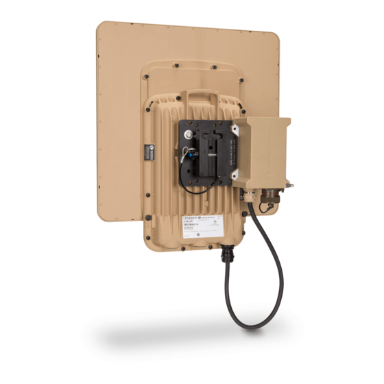
PTP 700 ATEX/HAZLOC Connectorized ODU (Global) C045070B015 PTP 700 ATEX/HAZLOC Connectorized ODU (EU) C045070B017 ODU kit part numbers Order PTP 700 Connectorized ODU kits from Cambium Networks (Table Each of the parts listed in Table 5 includes the following items: •... - Page 84 Chapter 2: System hardware Outdoor unit (ODU) Figure 10 PTP 700 Connectorized+Integrated ODU (front and rear views) Page 2-6...
- Page 85 (Software License Key page on page 6-11). Individual ODU part numbers Order PTP 700 Connectorized+Integrated ODUs from Cambium Networks (Table 4). Each of the parts listed in Table 4 includes the following items: •...
-
Page 86: Odu Capability Upgrades
6). For details of how to install the capability upgrades, refer to Generating license keys on page Software License Key page on page 6-11. Table 6 Capability upgrades available for PTP 700 Series ODUs Cambium description (*1) Part number PTP 700 128-bit AES Encryption – per END (*2) C000070K001A PTP 700 256-bit AES Encryption –... -
Page 87: Odu Accessories
PTP 650/700 8-Port T1/E1 Software License (per END). C000065K049A (*1) Order two upgrades per link. (*2) Cambium Networks will supply AES upgrades only if there is official permission to export AES encryption to the country of operation. ODU accessories Spare ODU port blanking plugs are available from Cambium Networks... - Page 88 Chapter 2: System hardware Outdoor unit (ODU) Figure 11 ODU mounting bracket (integrated) Figure 12 ODU mounting bracket (connectorized) Page 2-10...
- Page 89 Chapter 2: System hardware Outdoor unit (ODU) Figure 13 ODU extended integrated mounting bracket Figure 14 ODU large diameter extension kit Table 8 ODU mounting bracket part numbers Bracket Pole diameter ODU variants Bracket part number Mounting bracket 40 mm to 82 mm PTP 700 N000065L031 (integrated)
-
Page 90: Odu Interfaces
Chapter 2: System hardware Outdoor unit (ODU) Bracket Pole diameter ODU variants Bracket part number diameter extension kit inches) Connectoized+Integrated N000065L042 ODU interfaces The PSU, AUX and SFP ports are on the rear of the ODUs (Figure 15). These interfaces are described in Table 9. -
Page 91: Odu Specifications
Chapter 2: System hardware Outdoor unit (ODU) The front of the connectorized ODU (Figure 16) provides N type female connectors for RF cable interfaces to antennas with horizontal (H) and vertical (V) polarization. Figure 16 Connectorized ODU antenna interfaces Figure 17 Connectorized+Integrated ODU antenna interfaces ODU specifications The PTP 700 ODU conforms to the specifications listed in Table... - Page 92 Chapter 2: System hardware Outdoor unit (ODU) Temperature -40°C (-40°F) to +60°C (140°F) Wind loading 200 mph (323 kph) maximum. See ODU wind loading on page 3-14. Humidity 100% condensing Liquid and IP66, IP67 particle ingress UV exposure 10 year operational life (UL746C test evidence) Static Electromagnetic compatibility (EMC) compliance on page...
-
Page 93: Power Supply Units (Psu)
Do not connect the PIDU Plus PTP 300/500/600 Series to the PTP 700 ODU or LPU. Note Each of the ODU kits listed in Table 5 includes one PSU and one US or EU line cord as stated in the Cambium description. Page 2-15... -
Page 94: Psu Part Numbers
Chapter 2: System hardware Power supply units (PSU) PSU part numbers Order PSUs and (for AC power) line cords from Cambium Networks (Table 11). Table 11 Power supply component part numbers Cambium description Cambium part number PTP 650/700 AC+DC Enhanced Power Injector... -
Page 95: Psu Specifications
Chapter 2: System hardware Power supply units (PSU) Table 12 AC+DC Enhanced Power Injector interface functions Interface Function 100-240V 47-63Hz 1.5A AC power input (main supply). DC In Alternative DC power supply input. DC Out DC power output to a second PSU (for power supply redundancy) or to a NIDU. -
Page 96: Antennas And Antenna Cabling
ODU. Use weatherproof connectors, preferably ones that are supplied with adhesive lined heat shrink sleeves that are fitted over the interface between the cable and connector. Order CNT-400 RF cable and N type male connectors from Cambium Networks (Table 14). -
Page 97: Fcc And Ic Approved Antennas
(not PTP 700 LPUs) are required for protecting the antenna RF cables at building entry. One arrestor is required per antenna cable. One example of a compatible lightning arrestor is the Polyphaser LSXL-ME or LSXL (not supplied by Cambium Networks). FCC and IC approved antennas... - Page 98 Table 15 Antennas permitted for deployment in USA/Canada – 4.9 GHz Manufacturer Antenna type Nominal Cambium part gain (dBi) number RadioWaves Radio Waves 6-foot Parabolic, SP6-5.2 36.1 RadioWaves Radio Waves 6-foot Dual-Pol Parabolic, 36.0...
- Page 99 Chapter 2: System hardware Antennas and antenna cabling Manufacturer Antenna type Nominal Cambium part gain (dBi) number RadioWaves Radio Waves 3-foot Parabolic, SP3-4.7 30.4 N000000D005 RadioWaves Radio Waves 3-foot Dual-Pol Parabolic, 30.2 RDH4517 HPD3-4.7 Gabriel Gabriel 2.5-foot Standard Dual QuickFire 29.7...
- Page 100 Chapter 2: System hardware Antennas and antenna cabling Manufacturer Antenna type Nominal Cambium part gain (dBi) number RadioWaves Radio Waves 90 Sectorized (Dual-Pol), 16.4 N000000D003 SEC-47D-90-16 KPPA OMNI (Dual-Pol) 13.0 RadioWaves Radio Waves Omni Dual-Pol, OMND-4.8-9 Table 16 Antennas permitted for deployment in USA only – 5.1 GHz...
- Page 101 Chapter 2: System hardware Antennas and antenna cabling Manufacturer Antenna type Nominal Cambium part gain (dBi) number RadioWaves Radio Waves 3-foot Parabolic, SP3-5.2 RDH4513B Gabriel 2.5-foot Standard QuickFire Gabriel 30.8 Parabolic, QF2.5-52-N Gabriel 2.5-foot Standard Dual QuickFire Gabriel 30.7 Parabolic, QFD2.5-52-N...
- Page 102 Chapter 2: System hardware Antennas and antenna cabling Manufacturer Antenna type Nominal Cambium part gain (dBi) number Andrew 1-foot Flat Panel Single, UBP300- Andrew 20.6 Small Form Factor Flat Plate Antenna Part MARS Integrated # MA-EM56-DP19CM. Laird 60 Sectorized (Dual-Pol)
- Page 103 Chapter 2: System hardware Antennas and antenna cabling Manufacturer Antenna type Nominal Cambium part gain (dBi) number StellaDoradus StellaDoradus 4-foot Single-Pol, 56 32.4 PSD113 RadioWaves Radio Waves 3-foot Dual-Pol Parabolic, 32.3 RDH4509B HPD3-5.2NS RadioWaves Radio Waves 3-foot Parabolic, SP3-5.2 31.4...
- Page 104 Chapter 2: System hardware Antennas and antenna cabling Manufacturer Antenna type Nominal Cambium part gain (dBi) number MTI 15 inch Dual-Pol Flat Panel, MT- 485025/NVH Andrew Andrew 1.25-foot Flat Panel Dual, UBXP375-4-1 Andrew Andrew 1-foot Flat Panel Single, UBP300- MARS...
- Page 105 Chapter 2: System hardware Antennas and antenna cabling Manufacturer Antenna type Nominal Cambium part gain (dBi) number Andrew Andrew 3-foot Dual-Pol Parabolic, PX3F-52 33.4 Andrew Andrew 3-foot Parabolic, P3F-52 33.4 StellaDoradus StellaDoradus 4-foot Single-Pol, 56 32.4 PSD113 RadioWaves Radio Waves 3-foot Dual-Pol Parabolic, 32.3...
- Page 106 Chapter 2: System hardware Antennas and antenna cabling Manufacturer Antenna type Nominal Cambium part gain (dBi) number StellaDoradus StellaDoradus 2-foot Single-Pol, 56 PSD61 MARS MA-WS54-50R Flat Plate (Dual-Pol) Integrated MTI 15 inch Dual-Pol Flat Panel, MT- 485025/NVH Andrew Andrew 1.25-foot Flat Panel Dual,...
- Page 107 Chapter 2: System hardware Antennas and antenna cabling Manufacturer Antenna type Nominal Cambium part gain (dBi) number Andrew Andrew 4-foot Dual-Pol Parabolic, PX4F-52 34.9 RDG4453 Andrew Andrew 4-foot Parabolic, P4F-52 34.9 RDH4524 Gabriel Gabriel 4-foot Standard QuickFire 34.8 Parabolic, QF4-52-N...
- Page 108 Chapter 2: System hardware Antennas and antenna cabling Manufacturer Antenna type Nominal Cambium part gain (dBi) number Andrew Andrew 2-foot Dual-Pol Parabolic, PX2F-52 29.4 Andrew Andrew 2-foot Parabolic, P2F-52 29.4 MTI 3-foot Single-Pol, MT-487000/N RadioWaves Radio Waves 2-foot Parabolic, SP2-5.2...
- Page 109 Chapter 2: System hardware Antennas and antenna cabling Manufacturer Antenna type Nominal Cambium part gain (dBi) number Laird 90 Sectorized (Dual-Pol) KPPA OMNI (Dual-Pol) Page 2-31...
-
Page 110: Ethernet Cabling
Chapter 2: System hardware Ethernet cabling Ethernet cabling Ethernet standards and cable lengths All configurations require a copper Ethernet connection from the ODU (PSU port) to the PSU. Advanced configurations may also require one or both of the following: • A copper Ethernet connection from the ODU (Aux port) to an auxiliary device. -
Page 111: Outdoor Copper Cat5E Ethernet Cable
(Figure 20). Caution Always use Cat5e cable that is gel-filled and shielded with copper-plated steel. Alternative types of drop cable are not supported by Cambium Networks. Order Superior Essex type BBDGe cable from Cambium Networks (Table 22). Other lengths of this cable are available from Superior Essex. -
Page 112: Cable Grounding Kit
Optical cables do not require grounding. One grounding kit (Figure 21) is required for each grounding point on the PSU, Aux and copper SFP drop cables. Order cable grounding kits from Cambium Networks (Figure 30). Caution... -
Page 113: Lightning Protection Unit (Lpu) And Grounding Kit
Chapter 2: System hardware Ethernet cabling Lightning protection unit (LPU) and grounding kit PTP 700 LPUs provide transient voltage surge suppression for PTP 700 installations. Each PSU or Aux drop cable requires two LPUs, one near the ODU and the other near the linked device, usually at the building entry point (Table 24). -
Page 114: Lpu For Gps Drop Cables
24) is required for the PSU drop cable connection to the ODU. If the ODU is to be connected to an auxiliary device, one additional LPU and grounding kit is required for the Aux drop cable. Order the kits from Cambium Networks (Table 25). -
Page 115: Rj45 Connectors And Spare Glands
EMC glands must be used instead. EMC strain relief cable glands (quantity 5) are included in the LPU and grounding kit (Figure 23). These are identified with a black sealing nut. If extra glands are required, order them from Cambium Networks (in packs of 10) (Table 27). -
Page 116: Drop Cable Tester
The drop cable tester is an optional item for testing the resistances between the RJ45 pins of the drop cable (Figure 25). Order it by completing the order form on the support website (see Contacting Cambium Networks on page 1). Figure 25 Drop cable tester Indoor Cat5e cable To connect the PSU to network terminating equipment, use indoor Cat5e cable. -
Page 117: Sfp Module Kits
Chapter 2: System hardware Ethernet cabling SFP module kits SFP module kits allow connection of a PTP 700 Series ODU to a network over a Gigabit Ethernet interface in one of the following full-duplex modes: • Optical Gigabit Ethernet: 1000BASE-LX or 1000BASE-SX •... - Page 118 (Figure • Long EMC strain relief cable gland (Figure • The PTP 700 Series SFP Interface Upgrade Guide • License key instructions and unique Access Key Figure 26 Optical or copper SFP transceiver module Figure 27 Long cable gland Note PTP 700 does not support the Synchronous Ethernet or 1588 Transparent Clock features using copper SFP transceivers.
-
Page 119: Optical Cable And Connectors
Chapter 2: System hardware Ethernet cabling Optical cable and connectors Order an optical cable with LC connectors from a specialist fabricator, quoting the specification shown in Figure 28. It must be the correct length to connect the ODU to the other device. LC connectors should be supplied with dust caps to prevent dust build up. -
Page 120: Ptp-Sync Unit
Chapter 2: System hardware PTP-SYNC unit PTP-SYNC unit PTP-SYNC unit description The PTP-SYNC unit (Figure 29) is an optional component. It is required when TDD synchronization is implemented using PTP-SYNC. It measures the difference between the TDD frame timing and a 1 Hz timing reference, and signals this time difference to the ODU. For more information on this feature, refer to TDD synchronization on page 1-17. -
Page 121: Ptp-Sync Part Numbers
Chapter 2: System hardware PTP-SYNC unit PTP-SYNC part numbers Order PTP-SYNC kits and associated components from Cambium Networks (Table 31). Table 31 PTP-SYNC component part numbers Cambium description Cambium part number PTP-SYNC kit WB3665 PTP800 CMU / PTP-SYNC 19” rack mount installation kit... -
Page 122: Ptp-Sync Unit Interfaces
Input from GPS receiver or from the daisy-chained SYNC OUT signal of another PTP-SYNC. SYNC OUT Output to daisy-chained PTP-SYNC units. Input for software upgrades. Contact Cambium for instructions. 1PPS IN Coaxial alternative to GPS/SYNC IN. Peak input voltage must not exceed 5 V. LED bank... -
Page 123: Ptp-Sync Specifications
Chapter 2: System hardware PTP-SYNC unit PTP-SYNC specifications The PTP-SYNC unit conforms to the specifications listed in Table Table 35 Table Table 34 PTP-SYNC unit physical specifications Category Specification Dimensions Width excluding ears 174 mm (6.69 in) Width including ears 196 mm (7.54 in) Height 31.5 mm (1.21 in) Depth 79 mm (3.04 in) Weight... - Page 124 Chapter 2: System hardware PTP-SYNC unit There are two timing inputs to the PTP-SYNC unit: GPS/SYNC IN (RJ-45) (Table 37) and 1PPS IN (SMA) (Table 38). Table 37 PTP-SYNC unit timing specifications - GPS/SYNC IN (RJ-45) Category Specification Signal type Differential 1 Hz signal Common mode range –7 V to +7 V, relative to GPS/SYNC IN pin 2 (ground)
- Page 125 Chapter 2: System hardware PTP-SYNC unit The pinouts of the PTP-SYNC unit GPS/SYNC IN port are specified in Table Table 39 GPS/SYNC IN port pinouts Pin no. Connector pinout signal name Signal description Pin 1 12VGPS 12 V output to GPS receiver module, 250 mA max Pin 2 Ground Pin 3...
-
Page 126: Gps Receiver
Chapter 2: System hardware GPS receiver GPS receiver GPS receiver description The GPS receiver (Figure 32) is an optional timing reference source for PTP-SYNC. It provides a 1 Hz signal, accurately synchronized in frequency and phase across the network. Figure 32 GPS receiver The GPS receiver is supplier with a GPS adapter cable kit (Figure 33). -
Page 127: Gps Receiver Part Numbers
Chapter 2: System hardware GPS receiver GPS receiver part numbers Order GPS receivers and associated components from Cambium Networks (Table 40). Table 40 GPS receiver component part numbers Cambium description Cambium part number Trimble Acutime™GG GPS receiver WB4141 PTP-SYNC <-> Trimble Adapter Cable (*1) -
Page 128: Network Indoor Unit (Nidu)
PTP 700 AC+DC Enhanced Power Injector, the PTP 800 AC-DC Power Supply Converter or another source. Figure 34 NIDU Note To enable E1 or T1 capability over a PTP 700 link, purchase one access key for each link end from Cambium Networks (ODU capability upgrades on page 2-8). Page 2-50... -
Page 129: Nidu Part Numbers
Chapter 2: System hardware Network indoor unit (NIDU) NIDU part numbers Order NIDUs and associated components from Cambium Networks (Table 42). Table 42 NIDU component part numbers Cambium description Cambium part number Network Indoor Unit (One per END) C000065L043 NIDU - DC Power Connector Spare (10 pack) -
Page 130: Nidu Specifications
Chapter 2: System hardware Network indoor unit (NIDU) NIDU specifications The NIDU conforms to the specifications listed in Table Table 44 NIDU specifications Category Specification Dimensions Width 172 mm (6.8 in) Height 32 mm (1.3 in) Depth 218 mm (8.6 in) Weight 0.88 kg (1.95 lb) Temperature... - Page 131 Chapter 2: System hardware Network indoor unit (NIDU) Pin no. Connector pinout Signal description signal name (*) Pin 1 ODU_PHYn_PAIR1+ Gigabit tx/rx pair 1 Pin 2 ODU_PHYn_PAIR1- Gigabit tx/rx pair 1 Pin 3 ODU_PHYn_PAIR2+ Gigabit tx/rx pair 2 Pin 4 ODU_PHYn_PAIR3+ Gigabit tx/rx pair 3 Pin 5...
- Page 132 Chapter 3: System planning This chapter provides information to help the user to plan a PTP 700 link. The following topics are described in this chapter: • Typical deployment on page contains diagrams illustrating typical PTP 700 site deployments. • Site planning on page 3-11...
-
Page 133: Chapter 3: System Planning
Chapter 3: System planning Typical deployment Typical deployment This section contains diagrams illustrating typical PTP 700 site deployments. ODU with POE interface to PSU In the basic configuration, there is only one Ethernet interface, a copper Cat5e power over Ethernet (POE) from the PSU to the ODU (PSU port), as shown in the following diagrams: mast or tower installation (Figure 36 ), wall installation... - Page 134 Chapter 3: System planning Typical deployment Figure 37 Wall installation Page 3-3...
-
Page 135: E1 Or T1 Interfaces
Chapter 3: System planning Typical deployment Figure 38 Roof installation E1 or T1 interfaces There may be up to eight E1 or T1 channels connected to the ODU via the PSU port, as shown Figure 39. The NIDU is not compatible with the SFP or AUX ports. Page 3-4... - Page 136 Chapter 3: System planning Typical deployment Figure 39 ODU with E1 or T1 interfaces Page 3-5...
-
Page 137: Sfp And Aux Ethernet Interfaces
Chapter 3: System planning Typical deployment SFP and Aux Ethernet interfaces There may be one or two additional Ethernet interfaces connected to the ODU: one to the SFP port (copper or optical) and one to the Aux port, as shown in the following diagrams: •... - Page 138 Chapter 3: System planning Typical deployment Page 3-7...
- Page 139 Chapter 3: System planning Typical deployment Figure 42 ODU with Aux and PSU interfaces Page 3-8...
-
Page 140: Gps Receiver Interfaces
Chapter 3: System planning Typical deployment GPS receiver interfaces If a GPS receiver is deployed for PTP-SYNC, it may be mounted on the wall of the equipment building (Figure 43) (preferred option), or on a metal tower or mast (Figure 44). - Page 141 Chapter 3: System planning Typical deployment Figure 44 GPS receiver tower or mast installation Page 3-10...
-
Page 142: Site Planning
Chapter 3: System planning Site planning Site planning This section describes factors to be considered when planning the proposed link end sites, including grounding, lightning protection and equipment location for the ODU, PSU and PTP- SYNC unit (if installed). Grounding and lightning protection Warning Electro-magnetic discharge (lightning) damage is not covered under warranty. -
Page 143: Site Grounding System
Chapter 3: System planning Site planning Figure 45 Rolling sphere method to determine the lightning protection zones Zone A: In this zone a direct lightning strike is possible. Do not mount equipment in this zone. Zone B: In this zone, direct EMD (lightning) effects are still possible, but mounting in this zone significantly reduces the possibility of a direct strike. -
Page 144: Odu And External Antenna Location
Chapter 3: System planning Site planning ODU and external antenna location Find a location for the ODU (and external antenna for connectorized units) that meets the following requirements: • The equipment is high enough to achieve the best radio path. •... -
Page 145: Odu Wind Loading
Chapter 3: System planning Site planning ODU wind loading Ensure that the ODU and the structure on which it is mounted are capable of withstanding the prevalent wind speeds at a proposed PTP 700 site. Wind speed statistics should be available from national meteorological offices. -
Page 146: Hazardous Locations
Hazardous location compliance on page 4-27 Deployment of ATEX/HAZLOC ODUs PTP 700 Series Hazardous Location Guide PSU DC power supply If using the DC input on the AC+DC power injector, ensure that the DC power supply meets the following requirements: •... -
Page 147: Psu Location
Chapter 3: System planning Site planning PSU location Find a location for the AC+DC Enhanced Power Injector that meets the following requirements: • The AC+DC Enhanced Power Injector can be mounted on a wall or other flat surface. • The PSU is kept dry, with no possibility of condensation, flooding or rising damp. •... -
Page 148: Nidu Location
Chapter 3: System planning Site planning Mounting the GPS receiver module on the equipment building If mounting the GPS receiver for PTP-SYNC on the equipment building (Figure 43), select a position on the wall that meets the following requirements: • It must be below the roof height of the equipment building or below the height of any roof- mounted equipment (such as air conditioning plant). -
Page 149: Lpu Location
Chapter 3: System planning Site planning • If the tower is greater than 61 m (200 ft in height, the drop cable shield must be grounded at the tower midpoint, and at additional points as necessary to reduce the distance between ground cables to 61 m (200 ft) or less. - Page 150 Chapter 3: System planning Site planning Figure 46 ODU with PSU, Aux and copper SFP interfaces Page 3-19...
- Page 151 Chapter 3: System planning Site planning Figure 47 ODU with PSU, Aux and optical SFP interfaces Figure 48 Bottom LPU and surge protector Page 3-20...
-
Page 152: Radio Spectrum Planning
Chapter 3: System planning Radio spectrum planning Radio spectrum planning This section describes how to plan PTP 700 links to conform to the regulatory restrictions that apply in the country of operation. Caution It is the responsibility of the user to ensure that the PTP product is operated in accordance with local regulatory limits. -
Page 153: Regulatory Limits
(integrated) Regulatory limits Many countries impose EIRP limits (Allowed EIRP) on products operating in the bands used by the PTP 700 Series. For example, in the 5.4 GHz and 5.8 GHz bands, these limits are calculated as follows: • In the 5.4 GHz band (5470 MHz to 5725 MHz), the EIRP must not exceed the lesser of 30 dBm or (17 + 10 x Log Channel width in MHz) dBm. -
Page 154: Available Spectrum
Chapter 3: System planning Radio spectrum planning Available spectrum The available spectrum for operation depends on the regulatory band. When configured with the appropriate license key, the unit will only allow operation on those channels which are permitted by the regulations. Certain regulations have allocated certain channels as unavailable for use: •... -
Page 155: Avoidance Of Weather Radars (Usa Only)
Chapter 3: System planning Radio spectrum planning Regions with mandatory radar detection In regions that mandate DFS, the unit first ensures that there is no radar activity on a given channel for a period of 60 seconds before radiating on that channel. Once a channel has been selected for operation, the unit will continually monitor for radar activity on the operating channel. -
Page 156: Link Planning
The PTP 700 Series will operate at ranges from 100 m (330 ft) to 200 km (125 miles), within 3 modes: 0-40 km (0-25 miles), 0-100 km (0-62 miles) and 0-200 km (0-124 miles). Operation of the system will depend on obstacles in the path between the units. -
Page 157: Linkplanner For Synchronized Networks
Chapter 3: System planning Link planning LINKPlanner for synchronized networks TDD synchronization should be planned using LINKPlanner. This will provide the necessary TDD frame parameter values which are required to complete a synchronized installation. Please refer to the LINKPlanner User Guide. Path loss Path loss is the amount of attenuation the radio signal undergoes between the two ends of the link. -
Page 158: Calculating Data Rate Capacity
Chapter 3: System planning Link planning Calculating data rate capacity The data rate capacity of a PTP link is defined as the maximum end-to-end Ethernet throughput (including Ethernet headers) that it can support. It is assumed that Ethernet frames are 1518 octet. - Page 159 Chapter 3: System planning Link planning Calculation example Suppose that the link characteristics are: • PTP 700 variant = Lite • Link Symmetry = 1:1 • Link Mode Optimization = TDM • Modulation Mode = 64QAM 0.92 Dual • Channel Bandwidth = 10 MHz •...
-
Page 160: Planning For Connectorized Units
Chapter 3: System planning Planning for connectorized units Planning for connectorized units This section describes factors to be taken into account when planning to use connectorized ODUs with external antennas in PTP 700 links. When to install connectorized units The majority of radio links can be successfully deployed with the integrated antenna in the Connectorized+Integrated ODU. -
Page 161: Calculating Rf Cable Length (5.8 Ghz Fcc Only)
Chapter 3: System planning Planning for connectorized units Note Under Industry Canada regulations, this radio transmitter may only operate using an antenna of a type and maximum (or lesser) gain approved for the transmitter by Industry Canada. To reduce potential radio interference to other users, the antenna type and its gain should be so chosen that the equivalent isotropically radiated power (EIRP) is not more than that necessary for successful communication. -
Page 162: Configuration Options For Tdd Synchronization
Configuration options for TDD synchronization Configuration options for TDD synchronization This section describes the different configuration options that may be used for implementing TDD synchronization in the PTP 700 Series. Schematic diagrams are included. The PTP 700 supports the following TDD synchronization configurations: •... -
Page 163: Single Link Configuration With Ptp-Sync
Chapter 3: System planning Configuration options for TDD synchronization Single link configuration with PTP-SYNC Each link requires one PTP-SYNC unit connected to the master ODU and one compatible GPS receiver. Use this configuration where a site contains only one TDD master ODU. The GPS receiver and LPU can be replaced by an alternative compatible 1 Hz timing reference (Figure 49). -
Page 164: Cluster With Ptp-Sync And Gps Receiver
Chapter 3: System planning Configuration options for TDD synchronization Cluster with PTP-SYNC and GPS receiver Each link requires one PTP-SYNC unit. Each site requires one compatible GPS receiver. Collocated PTP-SYNC units are connected together in a daisy-chain. Between two and ten PTP- SYNCs may be chained in this way. -
Page 165: Cluster With Ptp-Sync And No Gps Receiver
Chapter 3: System planning Configuration options for TDD synchronization Cluster with PTP-SYNC and no GPS receiver Each link requires one PTP-SYNC unit. PTP-SYNC units are connected together in a daisy-chain. Between two and ten PTP-SYNCs may be chained in this way. One ODU is designated as a cluster master. -
Page 166: Data Network Planning
Chapter 3: System planning Data network planning Data network planning This section describes factors to be considered when planning PTP 700 data networks. Ethernet interfaces The PTP 700 Ethernet ports conform to the specifications listed in Table Table 54 PTP 700 Ethernet bridging specifications Ethernet Bridging Specification Protocol... -
Page 167: Ethernet Port Allocation
Chapter 3: System planning Data network planning Ethernet port allocation Port allocation rules Decide how the three ODU Ethernet ports will be allocated to customer Data Service, Second Data Service, Management Service and Local Management Service based on the following rules: •... - Page 168 Chapter 3: System planning Data network planning Figure 52 Ports and Services: Data + Local Management Management Agent Local Management Ethernet Port Relay Ethernet Port Customer Data Ethernet Wireless Port Relay Port PTP 700 ODU Figure 53 Ports and Services: Data + Local Management + Local Management Management Agent Local Management...
- Page 169 Chapter 3: System planning Data network planning Figure 54 Ports and Services: Data + In-Band Management Management Agent Ethernet Port Ethernet Port Customer Data and In-Band Management Ethernet Wireless Port Relay Port PTP 700 ODU Figure 55 Ports and Services: Data + In-Band Management + Local Management Management Agent Local Management...
- Page 170 Chapter 3: System planning Data network planning Figure 56 Ports and Services: Data + In-Band Management + Local Management + Local Management Management Agent Local Management Ethernet Port Relay Local Management Ethernet Port Relay Customer Data and In-Band Management Ethernet Wireless Port Relay...
- Page 171 Chapter 3: System planning Data network planning Figure 58 Ports and Services: Data + Out-Of-Band Management + Local Management Management Agent Local Management Ethernet Port Relay Out-of-Band Management Ethernet Ethernet Port Port Relay Customer Data Ethernet Wireless Port Relay Port PTP 700 ODU Figure 59 Ports and Services: Data + Second Data + In-Band Management (with Data) Management...
- Page 172 Chapter 3: System planning Data network planning Figure 60 Ports and Services: Data + Second Data + In-Band Management (with Data) + Local Management Management Agent Local Management Ethernet Port Relay Customer Data and In-Band Management Ethernet Ethernet Port Port Relay Second Data Ethernet...
- Page 173 Chapter 3: System planning Data network planning Figure 62 Ports and Services: Data + Second Data + In-Band Management (with Second Data) + Local Management Management Agent Local Management Ethernet Port Relay Second Data and In-Band Management Ethernet Ethernet Port Port Relay Customer Data...
- Page 174 Chapter 3: System planning Data network planning Data + In-Band Management + [Local Management] + [Local Management] Data + Out-of-Band Management + [Local Management] Data + Second Data + In-Band Management (with Data) + [Local Management] Data + Second Data + In-Band Management (with Second Data) + [Local Management] Data + Second Data + Local Management Ensure that the same service combination from Table 57...
- Page 175 Chapter 3: System planning Data network planning Figure 64 Example of independent mapping of services to ports Management Management Agent Agent Local Out-of-Band Management Management Port Relay Relay Port Out-of-Band Customer Management Data Main Main Relay Customer Data Wireless Wireless Port Relay Port...
-
Page 176: Vlan Membership
Chapter 3: System planning Data network planning VLAN membership Decide if the IP interface of the ODU management agent will be connected in a VLAN. If so, decide if this is a standard (IEEE 802.1Q) VLAN or provider bridged (IEEE 802.1ad) VLAN, and select the VLAN ID for this VLAN. -
Page 177: Qos Configuration Page
Chapter 3: System planning Data network planning PTP 700 provides eight queues for traffic waiting for transmission over the wireless link. Q0 is the lowest priority queue and Q7 is the highest priority queue. Traffic is scheduled using strict priority; in other words, traffic in a given queue is transmitted when all higher-priority queues are empty. -
Page 178: Daisy-Chaining" Ptp 700 Links
Chapter 3: System planning Data network planning “Daisy-chaining” PTP 700 links When connecting two or more PTP 700 links together in a network (daisy-chaining), do not install direct copper Cat5e connections between the PSUs. Each PSU must be connected to the network terminating equipment using the LAN port. -
Page 179: Tdm Network Planning
Chapter 3: System planning TDM network planning TDM network planning This section describes factors to be considered when planning PTP 700 TDM networks. Caution If the ODU port has negotiated a link at 100BASE-T, the NIDU will not send or receive TDM data, and will not bridge customer data traffic. -
Page 180: Network Management Planning
• RFC-4293 IP-MIB • PTP 700 Series proprietary MIB Note The proprietary MIBs are provided in the PTP 700 Series software download files in the support website (see Contacting Cambium Networks on page 1). Supported diagnostic alarms PTP 700 supports the diagnostic alarms listed in Table 167. -
Page 181: Enabling Snmp
Chapter 3: System planning Network management planning Enabling SNMP Enable the SNMP interface for use by configuring the following attributes in the SNMP Configuration page: • SNMP State (default disabled) • SNMP Version (default SNMPv1/2c) • SNMP Port Number (default 161) Page 3-50... -
Page 182: Security Planning
Chapter 3: System planning Security planning Security planning This section describes how to plan for PTP 700 links to operate in secure mode. Planning for SNTP operation Note PTP 700 does not have a battery-powered clock, so the set time is lost each time the ODU is powered down. -
Page 183: Planning For Snmpv3 Operation
Chapter 3: System planning Security planning Item Description Quantity required TLS Private Key An RSA private key of size 2048 bits, generated Two pairs per link. and Public in either PKCS#1 or PKCS#5 format, These items are unique Certificates unencrypted, and encoded in the ASN.1 DER to IP address. - Page 184 Chapter 3: System planning Security planning Web-based security management allows an operator to configure users, security levels, privacy and authentication protocols, and passphrases using the PTP 700 web-based management interface. The capabilities supported are somewhat less flexible than those supported using the MIB-based security management, but will be sufficient in many applications.
- Page 185 Chapter 3: System planning Security planning Table 60 Permitted character set for SNMPv3 passphrases Character Code Character Code <space> < “ > & A..Z 65..90 a..z 97..122 0..9 48..57 Identify up to two SNMP users that will be configured to receive notifications (traps). Identify the Internet address (IPv4 or IPv6) and UDP port number of the associated SNMP manager.
- Page 186 Chapter 3: System planning Security planning SNMPv3 default configuration (MIB-based) When SNMPv3 MIB-based Security Mode is enabled, the default configuration for the table is based on one initial user and four template users as listed in Table usmUserTable Table 61 Default SNMPv3 users Object Entry 1 Name...
- Page 187 Chapter 3: System planning Security planning VACM default configuration The default user is assigned to VACM group in the initial initial table. The template users are not assigned to a group. vacmSecurityToGroupTable PTP 700 creates default view trees and access as shown in Table 62 Table Table 62 Default VACM view trees...
-
Page 188: Planning For Radius Operation
Chapter 3: System planning Security planning Planning for RADIUS operation Configure RADIUS where remote authentication is required for users of the web-based interface. Remote authentication has the following advantages: • Control of passwords can be centralized. • Management of user accounts can be more sophisticated. For example; users can be prompted by a network manager to change passwords at regular intervals. -
Page 189: Planning For Fips 140-2 Operation
Chapter 3: System planning Security planning • Login(1): Read Only • Administrative(6): System Administrator • NAS Prompt(7): Read Only If the auth-role and service-type attributes are absent, PTP 700 selects the Read Only role. The auth-role vendor-specific attribute is defined in Table Table 64 Definition of auth-role vendor-specific attribute Field... - Page 190 Chapter 3: System planning Security planning • RADIUS authentication disabled. Caution Configure all of the above correctly to ensure that PTP 600 is operating in compliance with the FIPS 140-2 validation. Further reading For information about… Refer to… Generating security material for the HTTPS/TLS Planning for HTTPS/TLS operation on page interface...
-
Page 191: System Threshold, Output Power And Link Loss
Chapter 3: System planning System threshold, output power and link loss System threshold, output power and link loss Use the following tables to look up the system threshold (dBm), output power (dBm) and maximum link loss (dB) per channel bandwidth and modulation mode: Band Mode System threshold and output power (dBm) - Page 192 Chapter 3: System planning System threshold, output power and link loss Table 65 4.5 GHz IP mode: system threshold per channel bandwidth and output power (P) (dBm) Modulation mode 5 MHz 10 MHz 15 MHz 20 MHz P (all bands) BPSK 0.63 single -96.6 -95.1...
- Page 193 Chapter 3: System planning System threshold, output power and link loss Table 67 4.5 GHz TDM mode:system threshold per channel bandwidth and output power (P) (dBm) Modulation mode 5 MHz 10 MHz 15 MHz 20 MHz P (all bands) BPSK 0.63 single -96.6 -95.1 -93.3...
- Page 194 Chapter 3: System planning System threshold, output power and link loss Table 69 4.9 GHz IP mode: system threshold per channel bandwidth and output power (P) (dBm) Modulation mode 5 MHz 10 MHz 15 MHz 20 MHz P (all bands) BPSK 0.63 single -96.6 -95.1...
- Page 195 Chapter 3: System planning System threshold, output power and link loss Table 71 4.9 GHz TDM mode:system threshold per channel bandwidth and output power (P) (dBm) Modulation mode 5 MHz 10 MHz 15 MHz 20 MHz P (all bands) BPSK 0.63 single -96.6 -95.1 -93.3...
- Page 196 Chapter 3: System planning System threshold, output power and link loss Table 73 5.1/5.2 GHz IP mode: system threshold per channel bandwidth and o/p power (P) (dBm) Modulation mode 5 MHz P (all bands) BPSK 0.63 single -95.8 -94.3 -92.5 -91.3 -89.5 -88.3...
- Page 197 Chapter 3: System planning System threshold, output power and link loss Table 75 5.1/5.2 GHz TDM mode: system threshold per channel bandwidth and o/p pwr (P) (dBm) Modulation mode 5 MHz P (all bands) BPSK 0.63 single -95.8 -94.3 -92.5 -91.3 -89.5 -88.3...
- Page 198 Chapter 3: System planning System threshold, output power and link loss Table 77 5.4 GHz IP mode: system threshold per channel bandwidth and output power (P) (dBm) Modulation mode 5 MHz P (all bands) BPSK 0.63 single -96.6 -94.6 -92.8 -91.5 -89.8 -88.5...
- Page 199 Chapter 3: System planning System threshold, output power and link loss Table 79 5.4 GHz TDM mode: system threshold per channel bandwidth and output power (P)(dBm) Modulation mode 5 MHz P (all bands) BPSK 0.63 single -96.6 -94.6 -92.8 -91.5 -89.8 -88.5 -88.0...
- Page 200 Chapter 3: System planning System threshold, output power and link loss Table 81 5.8 GHz IP mode: system threshold per channel bandwidth and output power (P) (dBm) Modulation mode 5 MHz P (all bands) BPSK 0.63 single -96.8 -94.8 -93.0 -91.8 -90.0 -88.8...
- Page 201 Chapter 3: System planning System threshold, output power and link loss Table 83 5.8 GHz TDM mode: system threshold per channel bandwidth and output power (P)(dBm) Modulation mode 5 MHz P (all bands) BPSK 0.63 single -96.8 -94.8 -93.0 -91.8 -90.0 -88.8 -88.3...
-
Page 202: Data Throughput Capacity Tables
Chapter 3: System planning Data throughput capacity tables Data throughput capacity tables Use the following tables to look up the data throughput rates (Mbits/s) that are achieved when two PTP 700 ODUs are linked and the link distance (range) is 0 km: PTP 700 Link Link... - Page 203 Chapter 3: System planning Data throughput capacity tables symmetry optimization 15 MHz 10 MHz 5 MHz Figure 69 Figure 70 Figure 71 Figure 76 Figure 77 Figure 78 Figure 83 Figure 84 Figure 89 Figure 90 Figure 95 Figure 96 Adaptive Figure 104 Figure 105...
- Page 204 Chapter 3: System planning Data throughput capacity tables Table 85 Throughput at zero link range (Mbit/s), Full, symmetry 1:1, optimization IP Modulation mode 45 MHz (Tx/Rx/Aggregate) 40 MHz (Tx/Rx/Aggregate) 256QAM 0.81 dual 226.1 226.1 452.2 206.3 206.3 412.6 64QAM 0.92 dual 190.5 190.5 381.0...
- Page 205 Chapter 3: System planning Data throughput capacity tables 64QAM 0.75 dual 51.9 51.9 103.8 34.5 34.5 69.0 16QAM 0.87 dual 40.4 40.4 80.7 26.8 26.8 53.7 16QAM 0.63 dual 29.0 29.0 58.0 19.3 19.3 38.6 256QAM 0.81 single 37.7 37.7 75.4 25.0 25.0...
- Page 206 Chapter 3: System planning Data throughput capacity tables 16QAM 0.63 dual 77.8 77.8 155.6 71.6 71.6 143.3 256QAM 0.81 single 101.0 101.0 202.1 93.0 93.0 186.1 64QAM 0.92 single 85.1 85.1 170.2 78.4 78.4 156.8 64QAM 0.75 single 69.6 69.6 139.1 64.0 64.0...
- Page 207 Chapter 3: System planning Data throughput capacity tables 16QAM 0.87 single 19.5 19.5 39.0 13.2 13.2 26.3 16QAM 0.63 single 14.0 14.0 28.1 18.9 QPSK 0.87 single 19.5 13.1 QPSK 0.63 single 14.0 BPSK 0.63 single Modulation mode 5 MHz (Tx/Rx/Aggregate) 256QAM 0.81 dual 24.2 24.2...
- Page 208 Chapter 3: System planning Data throughput capacity tables QPSK 0.87 single 40.1 20.1 60.2 36.6 18.3 55.0 QPSK 0.63 single 28.9 14.4 43.3 26.3 13.2 39.5 BPSK 0.63 single 14.4 21.6 13.2 19.7 Modulation mode 30 MHz (Tx/Rx/Aggregate) 20 MHz (Tx/Rx/Aggregate) 256QAM 0.81 dual 200.5 100.2...
- Page 209 Chapter 3: System planning Data throughput capacity tables Page 3-78...
- Page 210 Chapter 3: System planning Data throughput capacity tables Table 88 Throughput at zero link range (Mbit/s), Full, symmetry 2:1, optimization TDM Modulation mode 45 MHz (Tx/Rx/Aggregate) 40 MHz (Tx/Rx/Aggregate) 256QAM 0.81 dual 280.8 140.4 421.2 257.7 128.9 386.6 64QAM 0.92 dual 236.6 118.3 354.8...
- Page 211 Chapter 3: System planning Data throughput capacity tables 64QAM 0.92 dual 83.2 41.6 124.9 55.9 27.9 83.8 64QAM 0.75 dual 68.0 34.0 102.0 45.7 22.8 68.5 16QAM 0.87 dual 52.9 26.5 79.4 35.5 17.8 53.3 16QAM 0.63 dual 38.0 19.0 57.1 25.5 12.8...
- Page 212 Chapter 3: System planning Data throughput capacity tables 16QAM 0.87 dual 120.52 40.17 160.70 79.54 26.51 106.05 16QAM 0.63 dual 86.64 28.88 115.52 57.18 19.06 76.24 256QAM 0.81 single 112.51 37.50 150.01 74.25 24.75 98.99 64QAM 0.92 single 94.79 31.60 126.38 62.56 20.85...
- Page 213 Chapter 3: System planning Data throughput capacity tables Table 90 Throughput at zero link range (Mbit/s), Full, symmetry 5:1, optimization IP Modulation mode 45 MHz (Tx/Rx/Aggregate) 40 MHz (Tx/Rx/Aggregate) 256QAM 0.81 dual 374.68 74.93 449.62 335.20 67.04 402.24 64QAM 0.92 dual 315.68 63.13 378.81...
- Page 214 Chapter 3: System planning Data throughput capacity tables 64QAM 0.92 dual 343.7 34.4 378.0 310.0 34.4 344.4 64QAM 0.75 dual 280.8 28.1 308.9 253.3 28.1 281.4 16QAM 0.87 dual 218.5 21.8 240.3 197.1 21.9 218.9 16QAM 0.63 dual 157.1 15.7 172.8 141.7 15.7...
- Page 215 Chapter 3: System planning Data throughput capacity tables 256QAM 0.81 single 60.1 15.0 75.1 33.2 16.6 49.8 64QAM 0.92 single 50.6 12.7 63.3 27.9 14.0 41.9 64QAM 0.75 single 41.4 10.3 51.7 22.8 11.4 34.3 16QAM 0.87 single 32.2 40.2 17.8 26.6 16QAM 0.63 single...
- Page 216 Chapter 3: System planning Data throughput capacity tables Table 92 Throughput at zero link range (Mbit/s), Lite, symmetry 1:1, optimization IP Modulation mode 45 MHz (Tx/Rx/Aggregate) 40 MHz (Tx/Rx/Aggregate) 256QAM 0.81 dual 113.0 113.0 226.0 103.0 103.0 206.0 64QAM 0.92 dual 95.0 95.0 190.0...
- Page 217 Chapter 3: System planning Data throughput capacity tables 64QAM 0.75 dual 26.0 26.0 52.0 17.0 17.0 34.0 16QAM 0.87 dual 20.0 20.0 40.0 13.0 13.0 26.0 16QAM 0.63 dual 15.0 15.0 30.0 10.0 10.0 20.0 256QAM 0.81 single 19.0 19.0 38.0 13.0 13.0...
- Page 218 Chapter 3: System planning Data throughput capacity tables Table 93 Throughput at zero link range (Mbit/s), Lite, symmetry 1:1, optimization TDM Modulation mode 45 MHz (Tx/Rx/Aggregate) 40 MHz (Tx/Rx/Aggregate) 256QAM 0.81 dual 100.0 100.0 200.0 93.0 93.0 186.0 64QAM 0.92 dual 84.0 84.0 168.0...
- Page 219 Chapter 3: System planning Data throughput capacity tables 64QAM 0.75 dual 25.0 25.0 50.0 17.0 17.0 34.0 16QAM 0.87 dual 20.0 20.0 40.0 13.0 13.0 26.0 16QAM 0.63 dual 14.0 14.0 28.0 18.0 256QAM 0.81 single 18.0 18.0 36.0 12.0 12.0 24.0 64QAM 0.92 single...
- Page 220 Chapter 3: System planning Data throughput capacity tables Table 94 Throughput at zero link range (Mbit/s), Lite, symmetry 2:1, optimization IP Modulation mode 45 MHz (Tx/Rx/Aggregate) 40 MHz (Tx/Rx/Aggregate) 256QAM 0.81 dual 150.0 75.0 225.0 137.0 68.0 205.0 64QAM 0.92 dual 126.0 63.0 189.0...
- Page 221 Chapter 3: System planning Data throughput capacity tables 64QAM 0.75 dual 35.0 17.0 52.0 23.0 11.0 34.0 16QAM 0.87 dual 27.0 13.0 40.0 18.0 27.0 16QAM 0.63 dual 19.0 10.0 29.0 13.0 19.0 256QAM 0.81 single 25.0 13.0 38.0 17.0 25.0 64QAM 0.92 single 21.0...
- Page 222 Chapter 3: System planning Data throughput capacity tables Table 95 Throughput at zero link range (Mbit/s), Lite, symmetry 2:1, optimization TDM Modulation mode 45 MHz (Tx/Rx/Aggregate) 40 MHz (Tx/Rx/Aggregate) 256QAM 0.81 dual 139.0 70.0 209.0 129.0 64.0 193.0 64QAM 0.92 dual 117.0 59.0 176.0...
- Page 223 Chapter 3: System planning Data throughput capacity tables 64QAM 0.75 dual 34.0 17.0 51.0 23.0 11.0 34.0 16QAM 0.87 dual 26.0 13.0 39.0 18.0 27.0 16QAM 0.63 dual 19.0 10.0 29.0 13.0 19.0 256QAM 0.81 single 25.0 12.0 37.0 17.0 25.0 64QAM 0.92 single 21.0...
- Page 224 Chapter 3: System planning Data throughput capacity tables Table 96 Throughput at zero link range (Mbit/s), Lite, symmetry 3:1, optimization IP Modulation mode 45 MHz (Tx/Rx/Aggregate) 40 MHz (Tx/Rx/Aggregate) 256QAM 0.81 dual 169.0 56.0 225.0 154.0 51.0 205.0 64QAM 0.92 dual 142.0 47.0 189.0...
- Page 225 Chapter 3: System planning Data throughput capacity tables 64QAM 0.92 dual 47.0 16.0 63.0 32.0 11.0 43.0 64QAM 0.75 dual 39.0 13.0 52.0 26.0 35.0 16QAM 0.87 dual 30.0 10.0 40.0 20.0 27.0 16QAM 0.63 dual 22.0 29.0 14.0 19.0 256QAM 0.81 single 28.0 37.0...
- Page 226 Chapter 3: System planning Data throughput capacity tables Table 97 Throughput at zero link range (Mbit/s), Lite, symmetry 5:1, optimization IP Modulation mode 45 MHz (Tx/Rx/Aggregate) 40 MHz (Tx/Rx/Aggregate) 256QAM 0.81 dual 187.0 37.0 224.0 168.0 34.0 202.0 64QAM 0.92 dual 158.0 32.0 190.0...
- Page 227 Chapter 3: System planning Data throughput capacity tables Figure 65 Range adjustment for PTP 700, symmetry 1:1, optimization IP, bandwidth 45 MHz 1.00 0.98 0.96 0.94 0.92 0.90 0.88 0.86 Range (km) Figure 66 Range adjustment for PTP 700, symmetry 1:1, optimization IP, bandwidth 40 MHz 1.00 0.98 0.96...
- Page 228 Chapter 3: System planning Data throughput capacity tables Figure 67 Range adjustment for PTP 700, symmetry 1:1, optimization IP, bandwidth 30 MHz 1.00 0.95 0.90 0.85 0.80 0.75 Range (km) Figure 68 Range adjustment for PTP 700, symmetry 1:1, optimization IP, bandwidth 20 MHz 1.00 0.95 0.90...
- Page 229 Chapter 3: System planning Data throughput capacity tables Figure 69 Range adjustment for PTP 700, symmetry 1:1, optimization IP, bandwidth 15 MHz 1.00 0.95 0.90 0.85 0.80 0.75 Range (km) Figure 70 Range adjustment for PTP 700, symmetry 1:1, optimization IP, bandwidth 10 MHz 1.00 0.95 0.90...
- Page 230 Chapter 3: System planning Data throughput capacity tables Figure 71 Range adjustment for PTP 700, symmetry 1:1, optimization IP, bandwidth 5 MHz 1.00 0.90 0.80 0.70 0.60 Range (km) Figure 72 Range adjustment for PTP 700, symmetry 1:1, optimization TDM, bandwidth 45 MHz 1.00 0.95 0.90...
- Page 231 Chapter 3: System planning Data throughput capacity tables Figure 73 Range adjustment for PTP 700, symmetry 1:1, optimization TDM, bandwidth 40 MHz 1.00 0.95 0.90 0.85 0.80 0.75 0.70 Range (km) Figure 74 Range adjustment for PTP 700, symmetry 1:1, optimization TDM, bandwidth 30 MHz 1.00 0.95 0.90...
- Page 232 Chapter 3: System planning Data throughput capacity tables Figure 75 Range adjustment for PTP 700, symmetry 1:1, optimization TDM, bandwidth 20 MHz 1.00 0.95 0.90 0.85 0.80 0.75 0.70 Range (km) Figure 76 Range adjustment for PTP 700, symmetry 1:1, optimization TDM, bandwidth 15 MHz 1.00 0.95 0.90...
- Page 233 Chapter 3: System planning Data throughput capacity tables Figure 77 Range adjustment for PTP 700, symmetry 1:1, optimization TDM, bandwidth 10 MHz 1.00 0.95 0.90 0.85 0.80 0.75 Range (km) Figure 78 Range adjustment for PTP 700, symmetry 1:1, optimization TDM, bandwidth 5 MHz 1.00 0.90 0.80...
- Page 234 Chapter 3: System planning Data throughput capacity tables Figure 79 Range adjustment for PTP 700, symmetry 2:1, optimization IP, bandwidth 45 MHz 1.00 0.95 0.90 0.85 0.80 Range (km) Figure 80 Range adjustment for PTP 700, symmetry 2:1, optimization IP, bandwidth 40 MHz 1.00 0.95 0.90...
- Page 235 Chapter 3: System planning Data throughput capacity tables Figure 81 Range adjustment for PTP 700, symmetry 2:1, optimization IP, bandwidth 30 MHz 1.00 0.95 0.90 0.85 0.80 0.75 0.70 Range (km) Figure 82 Range adjustment for PTP 700, symmetry 2:1, optimization IP, bandwidth 20 MHz 1.00 0.95 0.90...
- Page 236 Chapter 3: System planning Data throughput capacity tables Figure 83 Range adjustment for PTP 700, symmetry 2:1, optimization IP, bandwidth 15 MHz 1.00 0.95 0.90 0.85 0.80 0.75 Range (km) Figure 84 Range adjustment for PTP 700, symmetry 2:1, optimization IP, bandwidth 10 MHz 1.00 0.95 0.90...
- Page 237 Chapter 3: System planning Data throughput capacity tables Figure 85 Range adjustment for PTP 700, symmetry 2:1, optimization TDM, bandwidth 45 MHz 1.00 0.95 0.90 0.85 0.80 0.75 0.70 0.65 Range (km) Figure 86 Range adjustment for PTP 700, symmetry 2:1, optimization TDM, bandwidth 40 MHz 1.00 0.95 0.90...
- Page 238 Chapter 3: System planning Data throughput capacity tables Figure 87 Range adjustment for PTP 700, symmetry 2:1, optimization TDM, bandwidth 30 MHz 1.00 0.90 0.80 0.70 0.60 Range (km) Figure 88 Range adjustment for PTP 700, symmetry 2:1, optimization TDM, bandwidth 20 MHz 1.00 0.95 0.90...
- Page 239 Chapter 3: System planning Data throughput capacity tables Figure 89 Range adjustment for PTP 700, symmetry 2:1, optimization TDM, bandwidth 15 MHz 1.00 0.95 0.90 0.85 0.80 0.75 Range (km) Figure 90 Range adjustment for PTP 700, symmetry 2:1, optimization TDM, bandwidth 10 MHz 1.00 0.95 0.90...
- Page 240 Chapter 3: System planning Data throughput capacity tables Figure 91 Range adjustment for PTP 700, symmetry 3:1, optimization IP, bandwidth 45 MHz 1.00 0.95 0.90 0.85 0.80 0.75 0.70 0.65 Range (km) Figure 92 Range adjustment for PTP 700, symmetry 3:1, optimization IP, bandwidth 40 MHz 1.00 0.95 0.90...
- Page 241 Chapter 3: System planning Data throughput capacity tables Figure 93 Range adjustment for PTP 700, symmetry 3:1, optimization IP, bandwidth 30 MHz 1.00 0.95 0.90 0.85 0.80 0.75 0.70 0.65 Range (km) Figure 94 Range adjustment for PTP 700, symmetry 3:1, optimization IP, bandwidth 20 MHz 1.00 0.95 0.90...
- Page 242 Chapter 3: System planning Data throughput capacity tables Figure 95 Range adjustment for PTP 700, symmetry 3:1, optimization IP, bandwidth 15 MHz 1.00 0.95 0.90 0.85 0.80 0.75 0.70 0.65 Range (km) Figure 96 Range adjustment for PTP 700, symmetry 3:1, optimization IP, bandwidth 10 MHz 1.00 0.95 0.90...
- Page 243 Chapter 3: System planning Data throughput capacity tables Figure 97 Range adjustment for PTP 700, symmetry 5:1, optimization IP, bandwidth 45 MHz 1.00 0.95 0.90 0.85 0.80 0.75 0.70 0.65 Range (km) Figure 98 Range adjustment for PTP 700, symmetry 5:1, optimization IP, bandwidth 40 MHz 1.00 0.95 0.90...
- Page 244 Chapter 3: System planning Data throughput capacity tables Figure 99 Range adjustment for PTP 700, symmetry 5:1, optimization IP, bandwidth 30 MHz 1.00 0.95 0.90 0.85 0.80 0.75 0.70 0.65 0.60 Range (km) Figure 100 Range adjustment for PTP 700, adaptive, optimization IP, bandwidth 45 MHz 1.00 0.95 0.90...
- Page 245 Chapter 3: System planning Data throughput capacity tables Figure 101 Range adjustment for PTP 700, adaptive, optimization IP, bandwidth 40 MHz 1.00 0.95 0.90 0.85 0.80 0.75 Range (km) Figure 102 Range adjustment for PTP 700, adaptive, optimization IP, bandwidth 30 MHz 1.00 0.95 0.90...
- Page 246 Chapter 3: System planning Data throughput capacity tables Figure 103 Range adjustment for PTP 700, adaptive, optimization IP, bandwidth 20 MHz 1.00 0.95 0.90 0.85 0.80 0.75 0.70 0.65 Range (km) Figure 104 Range adjustment for PTP 700, adaptive, optimization IP, bandwidth 15 MHz 1.00 0.95 0.90...
-
Page 247: Tdm Traffic Load
Chapter 3: System planning Data throughput capacity tables Figure 105 Range adjustment for PTP 700, adaptive, optimization IP, bandwidth 10 MHz 1.00 0.95 0.90 0.85 0.80 0.75 0.70 Range (km) TDM traffic load Encapsulated data The NIDU supports separate management and TDM data protocol interfaces. The management interface is between the NIDU and a directly-connected ODU. - Page 248 Chapter 3: System planning Data throughput capacity tables In the best case (eight channels) the encapsulation has an efficiency of 91.6%. Timing only The resulting TDM traffic load in timing-only operation is shown in Table Table 99 TDM traffic load in timing-only Channels Octets per Ethernet frame E1 data rate (Mbit/s)
-
Page 249: Chapter 4: Legal And Regulatory Information
The following topics are described in this chapter: • Cambium Networks end user license agreement on page contains the Cambium and third party license agreements for the PTP 700 Series products. • Compliance with safety standards on page 4-22 lists the safety specifications against which the PTP 700 has been tested and certified. -
Page 250: Cambium Networks End User License Agreement
The word “Documentation” refers to electronic or printed manuals and accompanying instructional aids licensed to you. The word “Product” refers to Cambium Networks’ fixed wireless broadband devices for which the Software and Documentation is licensed for use. -
Page 251: Conditions Of Use
With regard to the copy made for backup or archival purposes, you agree to reproduce any Cambium Networks copyright notice, and other proprietary legends appearing thereon. Such copyright notice(s) may appear in any of several forms, including machine-readable form, and you agree to reproduce such notice in each form in which it appears, to the extent it is physically possible to do so. -
Page 252: Title And Restrictions
Software and Documentation and any copies made by you remain with Cambium Networks and its licensors. You will not, and will not permit others to: (i) modify, translate, decompile, bootleg, reverse engineer, disassemble, or extract the inner workings of the Software or Documentation, (ii) copy the look-and-feel or functionality of the Software or Documentation;... -
Page 253: Right To Use Cambium's Name
Software. Updates are available for download at the support website. Major features may be available from time to time for an additional license fee. If Cambium Networks makes available to you major features and no other end user license agreement is provided, then the terms of this Agreement will apply. -
Page 254: Disclaimer
Limitation of liability IN NO EVENT SHALL CAMBIUM NETWORKS BE LIABLE TO YOU OR ANY OTHER PARTY FOR ANY DIRECT, INDIRECT, GENERAL, SPECIAL, INCIDENTAL, CONSEQUENTIAL, EXEMPLARY OR OTHER DAMAGE ARISING OUT OF THE USE OR INABILITY TO USE THE PRODUCT... -
Page 255: Term Of License
Agreement by you. Within 30 days after termination of this Agreement, you will certify to Cambium Networks in writing that through your best efforts, and to the best of your knowledge, the original and all copies, in whole or in part, in any form, of the Software and all related material and Documentation, have been destroyed, except that, with prior written consent from Cambium Networks, you may retain one copy for archival or backup purposes. - Page 256 Chapter 4: Legal and regulatory information Cambium Networks end user license agreement Trademarks Java Technology and/or J2ME : Java and all other Java-based marks are trademarks or registered trademarks of Sun Microsystems, Inc. in the U.S. and other countries. UNIX : UNIX is a registered trademark of The Open Group in the United States and other countries.
- Page 257 Chapter 4: Legal and regulatory information Cambium Networks end user license agreement THIS SOFTWARE IS PROVIDED BY THE COPYRIGHT HOLDERS AND CONTRIBUTORS “AS IS” AND ANY EXPRESS OR IMPLIED WARRANTIES, INCLUDING, BUT NOT LIMITED TO, THE IMPLIED WARRANTIES OF MERCHANTABILITY AND FITNESS FOR A PARTICULAR PURPOSE ARE DISCLAIMED.
- Page 258 Chapter 4: Legal and regulatory information Cambium Networks end user license agreement • Redistributions in binary form must reproduce the above copyright notice, this list of conditions and the following disclaimer in the documentation and/or other materials provided with the distribution.
- Page 259 Chapter 4: Legal and regulatory information Cambium Networks end user license agreement • Redistributions of source code must retain the above copyright notice, this list of conditions and the following disclaimer. • Redistributions in binary form must reproduce the above copyright notice, this list of conditions and the following disclaimer in the documentation and/or other materials provided with the distribution.
- Page 260 Chapter 4: Legal and regulatory information Cambium Networks end user license agreement Redistribution and use in source and binary forms, with or without modification, are permitted provided that the following conditions are met: 1. Redistributions of source code must retain the above copyright notice, this list of conditions and the following disclaimer.
- Page 261 Chapter 4: Legal and regulatory information Cambium Networks end user license agreement If this package is used in a product, Eric Young should be given attribution as the author of the parts of the library used. This can be in the form of a textual message at program startup or in documentation (online or textual) provided with the package.
- Page 262 Chapter 4: Legal and regulatory information Cambium Networks end user license agreement Mark Adler madler@alumni.caltech.edu Libpng libpng versions 1.2.6, August 15, 2004, through 1.2.35, February 14, 2009, are Copyright © 2004, 2006-2008 Glenn Randers-Pehrson, and are distributed according to the same disclaimer and license as libpng-1.2.5 with the following individual added to the list of Contributing Authors...
- Page 263 Chapter 4: Legal and regulatory information Cambium Networks end user license agreement Tim Wegner The PNG Reference Library is supplied “AS IS”. The Contributing Authors and Group 42, Inc. disclaim all warranties, expressed or implied, including, without limitation, the warranties of merchantability and of fitness for any purpose.
- Page 264 Chapter 4: Legal and regulatory information Cambium Networks end user license agreement THIS SOFTWARE IS PROVIDED BY THE AUTHOR “AS IS” AND ANY EXPRESS OR IMPLIED WARRANTIES, INCLUDING, BUT NOT LIMITED TO, THE IMPLIED WARRANTIES OF MERCHANTABILITY AND FITNESS FOR A PARTICULAR PURPOSE ARE DISCLAIMED. IN NO...
- Page 265 Chapter 4: Legal and regulatory information Cambium Networks end user license agreement Apache Apache License Version 2.0, January 2004 http://www.apache.org/licenses/ TERMS AND CONDITIONS FOR USE, REPRODUCTION, AND DISTRIBUTION 1. Definitions. "License" shall mean the terms and conditions for use, reproduction, and distribution as defined by Sections 1 through 9 of this document.
- Page 266 Chapter 4: Legal and regulatory information Cambium Networks end user license agreement means any form of electronic, verbal, or written communication sent to the Licensor or its representatives, including but not limited to communication on electronic mailing lists, source code control...
- Page 267 Chapter 4: Legal and regulatory information Cambium Networks end user license agreement within a display generated by the Derivative Works, if and wherever such third-party notices normally appear. The contents of the NOTICE file are for informational purposes only and do not modify the License.
- Page 268 Chapter 4: Legal and regulatory information Cambium Networks end user license agreement of your accepting any such warranty or additional liability. END OF TERMS AND CONDITIONS APPENDIX: How to apply the Apache License to your work. To apply the Apache License to your work, attach the following boilerplate notice, with the fields enclosed by brackets "[]"...
- Page 269 Chapter 4: Legal and regulatory information Cambium Networks end user license agreement D3 JS library Copyright (c) 2013, Michael Bostock All rights reserved. Redistribution and use in source and binary forms, with or without modification, are permitted provided that the following conditions are met: * Redistributions of source code must retain the above copyright notice, this list of conditions and the following disclaimer.
-
Page 270: Compliance With Safety Standards
Chapter 4: Legal and regulatory information Compliance with safety standards Compliance with safety standards This section lists the safety specifications against which the PTP 700 has been tested and certified. It also describes how to keep RF exposure within safe limits. Electrical safety compliance The PTP 700 hardware has been tested for compliance to the electrical safety specifications listed in... -
Page 271: Power Density Exposure Limit
Chapter 4: Legal and regulatory information Compliance with safety standards • ANSI IEEE C95.1-1991, IEEE Standard for Safety Levels with Respect to Human Exposure to Radio Frequency Electromagnetic Fields, 3 kHz to 300 GHz. • Council recommendation of 12 July 1999 on the limitation of exposure of the general public to electromagnetic fields (0 Hz to 300 GHz) (1999/519/EC) and respective national regulations. - Page 272 Chapter 4: Legal and regulatory information Compliance with safety standards Calculation of power density The following calculation is based on the ANSI IEEE C95.1-1991 method, as that provides a worst case analysis. Details of the assessment to EN50383:2002 can be provided, if required. Peak power density in the far field of a radio frequency point source is calculated as follows: ��������...
- Page 273 Chapter 4: Legal and regulatory information Compliance with safety standards Table 102 Minimum safe distances for PTP 700 at maximum transmitter power Antenna P (W) d (m) (*1) (*2) (*3) Parabolic 6 ft (38.1 dBi) 0.635 5248.1 5.15 Flat plate 2 ft (28.5 dBi) 0.635 575.4 1.71...
- Page 274 Chapter 4: Legal and regulatory information Compliance with safety standards Table 103 Minimum safe distances for FCC bands Band Antenna P (W) d (m) (*1) (*2) (*3) 4.9 GHz Parabolic 6 ft (37.2 dBi) 0.127 4265.8 2.07 Flat Plate (28.0 dBi) 0.326 512.9 1.15...
-
Page 275: Hazardous Location Compliance
Chapter 4: Legal and regulatory information Compliance with safety standards Hazardous location compliance The PTP 700 ATEX/HAZLOC ODUs have been certified for operation in the following hazardous locations: ATEX The products have been approved under an “Intrinsic Safety” assessment as defined in EN60079-11:2007. -
Page 276: Compliance With Radio Regulations
Caution Changes or modifications not expressly approved by Cambium Networks could void the user’s authority to operate the system. Caution For the connectorized version of the product and in order to reduce potential radio... -
Page 277: Type Approvals
Chapter 4: Legal and regulatory information Compliance with radio regulations Type approvals The system has been tested against various local technical regulations and found to comply. Table 104 Table 108 list the radio specification type approvals that have been granted for PTP 700 products. -
Page 278: Fcc/Ic Compliance
Chapter 4: Legal and regulatory information Compliance with radio regulations Table 108 Radio certifications (5.8 GHz) Region Regulatory approvals FCC 47 CFR Part 15 C Canada IC RSS-210 Issue 8, Annex 8 (or latest) Denmark Radio Interface 00 007 Eire ComReg 02/71R4 Germany Order No 47/2007... - Page 279 Chapter 4: Legal and regulatory information Compliance with radio regulations Figure 106 FCC and IC certifications on Connectorized+Integrated ODU product labels Figure 107 FCC and IC certifications on Connectorized ODU product labels Industry Canada product labels Industry Canada Certification Numbers are reproduced on the product labels for the FCC/IC regional variant (Figure 106 Figure...
- Page 280 Chapter 4: Legal and regulatory information Compliance with radio regulations Figure 109 IC certification on Connectorized ODU product labels 4.9 GHz FCC and IC notification The system has been approved under FCC Part 90 and Industry Canada RSS-111 for Public Safety Agency usage.
- Page 281 Chapter 4: Legal and regulatory information Compliance with radio regulations Utilisation de la bande 5.4 GHz FCC et IC Cet appareil est conforme à la Section 15E de la réglementation FCC aux États-Unis et aux règlementations et avec Industrie Canada RSS-210 Annexe 9. Son fonctionnement est soumis aux deux conditions suivantes: (1) Ce dispositif ne doit pas causer d'interférences nuisibles, et (2) Cet appareil doit tolérer toute interférence reçue, y compris les interférences pouvant entraîner un fonctionnement indésirable.
- Page 282 Chapter 4: Legal and regulatory information Compliance with radio regulations The PTP 700 takes into account the antenna gain and cable loss configured by the professional installer in the web-based interface to limit the EIRP to ensure regulatory compliance. No additional action is required by the installer to reduce transmitter power in band edge channels.
- Page 283 Chapter 4: Legal and regulatory information Compliance with radio regulations The maximum EIRP in band edge channels for the USA and Canada 5.2 GHz band is listed in Table 110. Table 110 Edge channel power reduction in regulatory band 38 Channel Bandwidth Channel Frequency Maximum EIRP...
- Page 284 Chapter 4: Legal and regulatory information Compliance with radio regulations Réduction de puissance aux bords de la bande 5.4 GHz La Puissance isotrope rayonnée équivalente (PIRE) est limitée dans les canaux en bord de la bandes lorsque le PTP 700 est configuré pour utiliser la band 5,4 GHz aux les Etats-Unis ou au Canada.
- Page 285 Chapter 4: Legal and regulatory information Compliance with radio regulations The maximum transmitter power in band edge channels for the FCC 5.8 GHz band is listed in Table 112. Réduction de puissance aux bords de la bande 5.8 GHz La Puissance isotrope rayonnée équivalente (PIRE) est limitée dans les canaux en bord de la bandes lorsque le PTP 700 est configuré...
-
Page 286: European Union Compliance
Chapter 4: Legal and regulatory information Compliance with radio regulations Note Under Industry Canada regulations, this radio transmitter may only operate using an antenna of a type and maximum (or lesser) gain approved for the transmitter by Industry Canada. To reduce potential radio interference to other users, the antenna type and its gain should be so chosen that the equivalent isotropically radiated power (EIRP) is not more than that necessary for successful communication. - Page 287 Hereby, Cambium Networks declares that the PTP 700 product complies with the essential requirements and other relevant provisions of Directive 1999/5/EC. The declaration of...
- Page 288 Chapter 4: Legal and regulatory information Compliance with radio regulations 5.8 GHz operation in the UK The PTP 700 Connectorized product has been notified for operation in the UK, and when operated in accordance with instructions for use it is compliant with UK Interface Requirement IR2007.
Need help?
Do you have a question about the PTP 700 Series and is the answer not in the manual?
Questions and answers