Table of Contents
Advertisement
25
S
WALL MOUNTED COMBINATION BOILERS FOR CENTRAL HEATING
AND MAINS FED DOMESTIC HOT WATER
Installation AND
SERVICING INSTRUCTIONS
This appliance is for use with Natural Gas or LPG (Cat II 2H3P).
25Si GC NUMBER 47 311 49 (N.G.)
28Si GC NUMBER 47 311 51 (N.G.)
25
Minimum
8.5 kW
Maximum
25.0kW
IMPORTANT: THESE INSTRUCTIONS APPLY IN THE UK ONLY
AND MUST BE LEFT WITH THE USER OR AT THE GAS METER
Read the instructions before starting work - they have been written to make
the installation easier and prevent hold-ups.
i / 28
0
I
APPLIANCE OUTPUTS
Domestic
Hot Water
28
8.5kw
8.5 kW
28.0kw
25.0kW
S
CG NUMBER 47 311 50 (L.P.G.)
CG NUMBER 47 311 52 (L.P.G.)
25
28
8.5kw
28.0kw
i
Advertisement
Table of Contents

Related Manuals for Worcester 28Si


Summary of Contents for Worcester 28Si
-
Page 1: Servicing Instructions
This appliance is for use with Natural Gas or LPG (Cat II 2H3P). 25Si GC NUMBER 47 311 49 (N.G.) CG NUMBER 47 311 50 (L.P.G.) 28Si GC NUMBER 47 311 51 (N.G.) CG NUMBER 47 311 52 (L.P.G.) APPLIANCE OUTPUTS... - Page 2 2.1 General Information any other relevant standards. The appliance is set to give the maximum output of 28 kW [28Si] BS5440:1 - Flues and ventilation for gas appliances: Flues or 25kW [25Si] to the domestic hot water and to the heating BS5440:2 - Flues and ventilation for gas appliances: Air supply.
- Page 3 This can result in a pressure 15.4.2,3 and 4. The burner part numbers are: build-up that may cause damage to the boiler and household NG (25Si and 28Si) 8 718 120 565 0 devices such as showers, washing machines etc.
- Page 4 The data plate is fixed to the inner casing cover. Table 1. 25Si Table 1. 28Si NOMINAL BOILER RATINGS (10 Minutes After Lighting) NOMINAL BOILER RATINGS (10 Minutes After Lighting) BOILER ADJUSTED FOR G20 (Natural Gas) BOILER ADJUSTED FOR G20 (Natural Gas)
- Page 5 DOMESTIC HOT WATER SPECIFIC RATE - 30°C RISE l/min 12.0 13.4 MAXIMUM DOMESTIC HOT WATER FLOW RATE - 40°C RISE l/min 10.0 NOx CLASSIFICATION FOR BOTH 25 & 28Si Class 2 SEDBUK NUMBER 78.0 78.2 SEDBUK BAND Table 6 DOMESTIC HOT WATER TEMPERATURE RISE...
- Page 6 4. Siting The Appliance Fig. 3. Appliance casing dimensions and required clearances (front view). The appliance may be installed in any room but refer to the requirements of the current IEE Regulations and, in Scotland, the relevant electrical provisions of the Building Regulations with respect to the installation of appliances in rooms containing baths or showers.
- Page 7 5. Flue terminal positions 6. Air Supply The flue system must be installed following the requirements of 6.1 The appliance does not require a separate vent for BS5440: 1. combustion air. Standard flue kit length is 330 - 725mm (as measured from the 6.2 The appliance can be fitted in a cupboard with no vents for centre of the flue turret) with extension kits for flues up to cooling but the minimum clearances must be increased to those...
- Page 8 The system and the appliance must be properly vented. 7. Sealed System Repeated venting loses water from the system, which must be replaced. The make-up connection must be close to the The system must comply with requirements of BS6798 and appliance in the heating return pipe through an approved non- BS5449 and must not be operated without being full of water return valve.
- Page 9 The maximum hot water flow rate is set at the factory to 10 and that the gas flow is adequate for all the installed gas l/min [28Si] or 9 l/min [25Si] giving a nominal temperature rise appliances operating together. of 40°C with the temperature control at maximum. Refer to Table 6.
- Page 10 Fig. 11. Wiring diagram. Overheat cut-off device CH sensor (front of heat exchanger) Flame sense electrode Spark electrode Gas valve Flow Pump switch Main Main Spark transformer DHW sensor Control Board ST16 ST12 ST15 Link pink 2 blue 2 yellow Mains in 2 brown 2 green...
- Page 11 Fig. 12. Functional flow diagram. Inputs Outputs DHW control knob CH Control knob Electronics/ microprocessor CH pressure adjust pot (Safety Low Voltage) Gas valve mode switch Reset button Convert AC to low voltage electronics Electronics Pump Electronics...
- Page 12 Fig 13 - Replacement internal fuses Fig.14 . Mains electricity connections. Bottom Left Hand Side - Facia NOTE: Check the size of the fuse before fitting ST12 Live N LS 230V Brown Neutral Blue Earth External control Green/Yellow Mains lead Strain relief clamp 1.
- Page 13 Fig.16 . Manifold assembly Fig.18. Inner case and facia fixing Fixing screws Position of the cabinet Wall fixing screw Frame Wall Fibre Frame Washer Inner case cover Facia panel fixing screws Flow Flow Cold Inlet Return Facia All dimensions in mm 11.7 Install the Boiler Remove the cabinet by unscrewing the screw at the top front and releasing the sides.
- Page 14 11.9 Measure and Cut the Ducts. General: Cut the ducts as necessary, ensuring that the ducts are Fig.20. Standard flue assembly square and free from burrs. Always check the dimensions before cutting. Measure the distance L. Refer to Fig. 22 and 23. The standard flue can be telescopically adjusted to any length Terminal assembly...
- Page 15 Make good the internal wall face and the external brickwork or rendering. 11.11 Fitting of the Flue Assembly without access to the Terminal. A rubber gasket kit is available from Worcester Heat Systems. NOTE: A larger diameter opening in the wall is required. Refer to Rubber sealing Table 2.
- Page 16 Fig.26. Flue bends Y-162 Plain tube If more than two extension ducts are needed in any section to achieve the required length then the final section of the Fig.27 - Elbow to Flue Turret 120mm assembly must not be less than 325mm without cutting the Assembly.
- Page 17 Cover panel Fig.29. Facia connections cover Fig.30. Programmer cover Facia Controls connections cover Programmer connections Facia Fixing screw Facia bottom panel (clip-on) Fig 32 - Mains Voltage External Controls Connections NOTE: Only double insulated controls not requiring an earth can be used Ns Ls L Ns Ls L Fig.31.
- Page 18 Fig. 35. Pump venting. 12. Commissioning The Appliance Pump Benchmark Water Treatment: For optimum performance after installation, this boiler and its associated central heating system should be flushed in accordance with the guidelines given in BS7593:1992 - Treatment of water in domestic hot water systems.
- Page 19 Close the tap. Worcester Heat Systems Service Department should be The appliance will then return to the central heating mode and contacted.
- Page 20 If the appliance is to be passed over to the user immediately starting any service procedures. then set the controls to the users requirements. Always test for gas soundness after the service has been If the appliance is to be left inoperative in frosty conditions then completed.
- Page 21 Fig.41. Inner case components Flue spigot Inner casing Combustion products test point (front cap) Fan assembly Flue hood Overheat thermostat (at rear) Combustion chamber/flue hood fixing screws Primary sensor Heat exchanger Combustion Combustion chamber fixing chamber fixing screw screw Combustion chamber Burner Burner...
- Page 22 Fig.43. Flue hood Fig.42. Fan assembly Fan assembly Flue hood fixing screws Fan assembly fixing screws Air flow sensing tube Flue hood Air flow sensing tube (red) Flue hood Flue hood/Heat exchanger guide Fig.44. Burner assembly Burner blade Spark electrode assem- assembly Flame sense electrode...
- Page 23 Fig.45 . Lower casing - gas and water Gas Valve controls. Pump connection Air flow switch Expansion vessel con- nection Water flow switch Pump Red tube (+ve) Pump connection Clear tube (-ve) Pressure gauge Relief valve Earth Boiler drain connection connection Transformer Facia assembly...
- Page 24 Fig.48. Combustion Chamber Insulation. Fig.50. Pressure Gauge capillary fixing Pressure gauge capillary fixing clip Insulation panel-front Boiler drain ON/OFF Combustion chamber assembly Boiler drain tube Fixing connection screws (tube attached) Relief valve Pressure gauge Relief valve Insulation capillary fixing clip panel-side Do not omit the O-ring from the pressure capillary when fitting the replacement gauge.
- Page 25 The new flow-switch must be set to deliver the correct flow rate Unscrew the four screws and remove the metal cover. Refer to Fig to give a temperature rise of 40°C ie 10 l/min (28Si) or 9 l/min (25Si). Lift out the control board. Refer to Fig 55...
- Page 26 15.4.11 Transformer Do not omit the heat transfer paste when fitting the replacement Remove the cabinet and lower the facia panel as described in sensor. Section 14, Inspection and Servicing. 15.4.16 Overheat Thermostat Unscrew the four screws and remove the metal cover. Refer to Fig Remove the cabinet and the inner casing.
- Page 27 15.4.18 Pump Check that the primary circuit has been fully drained as Fig.60. Primary heat exchanger described in 15.3 preceding. Release the water connections and remove the pump. Refer to Fig 45. Heat Exchanger Disconnect and transfer the electrical connections to the new Central heating flow Central heating return pump.
- Page 28 Gas Valve Junkers 8 747 003 381 0 E27-596 Burner (NG) Vulcano 8 718 120 565 0 E27-597 Burner (LPG) 28Si Vulcano 8 718 120 566 0 E27-598 Burner (LPG) 25Si Vulcano 8 718 120 569 0 E27-600 Primary Heat Exchanger...
- Page 30 17. Operational Flow Diagrams Room CENTRAL HEATING FUNCTION thermostat and/or mains programmer (or link) On Electronic MAIN SWITCH Green Light facia programmer (if fitted) On ST13 link in CH control knob On Two minute CH light On. minimum Modulate gas Pump On.
- Page 31 OVERRUN FUNCTION If primary temp above 80° fan If primary rises Fan overrun runs until temp above 85° fan END DHW function active below 80°C DEMAND runs until temp for 3 minutes (35 seconds falls below 80° minimum) If primary temp below 80°...
- Page 32 18. Fault Finding Note: This fault-finding information is for guidance only. Worcester Heat Systems cannot be held responsible for costs incurred by persons not deemed to be competent. The electronic control system for this boiler incorporates four lights on the facia. These are used to show normal operating status. But as a secondary function, by flashing, they can also be used to help provide fault diagnostics.
- Page 33 Is the facia on/off switch turned on? Turn switch on. `(Clockwise) Is there a 230V AC live supply across Check electrical Terminal ST12 pins L supply to boiler. and N Replace control board Has fuse F1 blown? (Section 15.4.10) Replace fuse and investigate cause. Suggestions: Cable damage, connections to (or faults within) pump, fan, external 230V controls, transformer or board.
- Page 34 With CH control knob fully clockwise, does There is no heat Is there 230V AC the boiler ignite and demand. Check room across terminal ST8 appear to run thermostat or mains pins LR and N? normally in central programmer (or link). heating mode? Red diode is Is there a link at...
- Page 35 Replace control board. Is the boiler in a very (Section 15.4.10). cold environment (less Note: A damp board than 5°C)? could cause this fault. Boiler is running in “Autofrost stat” mode. See Section 17. Is the boiler fully Rectify fault. water pressurised and is all air vented? Repair or replace...
- Page 36 Is the gas supply Rectify gas supply connected and at the problem. correct pressure? Remove front panel. Remove inner cover. Repair or replace Reset and restart the Reset and restart the Are the electrodes and spark electrode boiler. Can a flame be boiler.
- Page 37 Is the multiway connector at board position ST16 pushed Push fully home fully home on to the board? Check the DHW sensor. Is it correctly Re-fix sensor onto pipe fitted onto the pipe with heat conductive paste between the pipe and sensor? Remove multiway connector from board position ST16.
- Page 38 Turn off boiler. Is there Does the fan run Remove the fan continuity across the before the fault connector from board C and NO terminals of occurs? position ST1 and the air pressure switch restart the boiler. Is (where green wires are Replace control board.
- Page 39 The gas valve mode Turn to 'NORM' switch (concealed by position the facia side panel) is not set correctly Light indication during fault not Control board is likely covered by above to be wet or damaged details. or malfunctioning. Check for wet board or connections.
- Page 40 This manual is to be used in conjunction with the variant part number of the bar code below: Bosch Group Worcester Heat Systems Limited (Bosch Group), Cotswold Way, Warndon, Worcester WR4 9SW. Telephone: (01905) 754624. Fax: (01905) 754619. Technical Helpline (08705) 266241. www.worcester-bosch.co.uk This booklet is accurate at the date of printing but will be superseded and should be disregarded if specifications and/or appearances are changed in the interests of continued improvement.
- Page 41 Replace white case. Fig. 1. Programmer connection 1 Dial 2 Time Pointer 3 Manual Selector 4 Tappets Worcester Heat Systems Limited, Cotswold Way, Warndon, Worcester WR4 9SW. 8 716 145 228a 01/00 Telephone: (01905) 754624. Fax: (01905) 754619. Technical Helpline (0990) 266241.
-
Page 42: Flue System
41 311 43/45 47 311 54 24SBi 41 311 44/46 25Si 47 311 49/50 9/14 CBi 41 311 50/51 28Si 47 311 51/52 14/19 CBi 41 311 52/53 47 311 51 19/24 CBi 41 311 54/55 24CDi 47 311 30/31... - Page 43 1. Flue Terminal Position Fig. 1. Terminal Position Pitched Roof The Flue System must be installed in accordance with BS 5440: Part 1 2000 where applicable. When installed the minimum clearance between the terminal and any adjoining vertical walls or obstructions must be at least 500mm.
- Page 44 The maximum equivalent flue heights, excluding the flue terminal assembly are: Table 2. 24i, 28i, 35CDi II 2.3m Equivalent WR325, WH1 2.6m Length 4m 25Si, 28Si, C1 3.0m 15SBi, 24SBi, 24CDi, 80ic 4.0m 9/14, 14/19CBi 3.0m Equivalent 19/24CBi 2.25 length 2x750mm 28CDi 3.5m...
- Page 45 Fig. 5. Adaptor 3. Preparation and General Notes Ensure the ducts are correctly located into 3.1. FLUE HEIGHT AND OFFSETS. the socketed joints. Determine the height of the flue system and if offsets are Fixing screws needed for the system to miss ceiling/roof joists and any other obstruction.
- Page 46 3.8. POSITIONING THE FLUE SYSTEM It may be necessary to deviate from the following method of installation because of site conditions. However, joints must be sealed and fixed as described. Align the centre of the flue spigot with the ceiling and mark the centre position.
- Page 47 4. Measurement of Ducts 4.1 AIR AND FLUE DUCT LENGTHS - NO OFFSET For a flat roof measure the distance from the appliance top panel to the outside edge of the hole diameter marked on the inside surface of the roof. This is dimension 'E ' Refer to Fig.
- Page 48 4.2 AIR AND FLUE DUCT LENGTHS - OFFSET WITH VERTICAL 2nd Vertical Section: Measure the distance from centre-line of the horizontal offset ADAPTER (90° or, where applicable, 45° bends) to the outside edge of the hole diameter marked on the 1st Vertical Section: inside surface of the roof.
- Page 49 4.3 AIR AND FLUE DUCT LENGTHS - OFFSET WITHOUT Vertical Section: VERTICAL ADAPTER (90° or, where applicable, 45° bends) Measure the distance from the centre-line of the horizontal Measure the distance from the centre of the flue spigot on offset to the outside edge of the hole diameter marked on the top of the appliance to the centre line of the vertical sections.
- Page 50 Fig. 12. Vertical flue system (offset with 45° flue bends) Air inlet flange Weather sealing collar (Secure with screw provided and seal with silicone sealant) 300mm Roof flashing (not supplied) minimum Flat roof Height of terminal assembly 1100mm G = 1100mm - F L = K - G Flue terminal assembly (106mm diameter)
- Page 51 5.5 ASSEMBLY OF DUCTS 5.8 FIX THE FLUE SYSTEM ASSEMBLY TO THE APPLIANCE 5.5.1 AIR DUCTS From inside the building, assemble the flue system starting Check the assembled length of the ducts. Drill two holes at the appliance. refer to Fig. 6, 8, 9 and 10. through the pilot holes in the expanded end of the air duct Align the flue assembly or the first section of flue with the and fix the ducts together with the screws provided.
- Page 52 Important: Do not forget to fix the fire stop spacer as the assembly of the system proceeds. 5.9 FIX THE FLUE TERMINAL ASSEMBLY Fit the roof flashing loosely to the roof. From outside, pass the terminal assembly through the roof flashing.
- Page 53 Bosch Group Worcester Heat Systems Limited, Cotswold Way, Warndon, Worcester WR4 9SW. Telephone: (01905) 754624. Fax: (01905) 754619. Technical Helpline (0990) 266241. www.worcester-bosch.co.uk This booklet is accurate at the date of printing but will be superseded and should be disregarded if specifications and/or appearances are changed in the interests of continued improvement.
- Page 54 DIGITAL SINGLE-CHANNEL PROGRAMMER FITTING AND OPERATING INSTRUCTIONS General information is given in the users instruction leaflet despatched with the appliance and/or on the lighting instruction plate fitted to the appliance. TWICE ONCE CONFORMS TO THE ESSENTIAL REQUIREMENTS OF THE FOLLOWING DIRECTIVES: 89/336/EEC - Electromagnetic compatibility 73/23/EEC - Low voltage Directive THESE INSTRUCTIONS APPLY IN THE UK ONLY...
- Page 55 Gas Safety (Installation and Use) Regulations 1984 : All gas appliances must be installed by a competent person, in accordance with the above regulations. Failure to install the appliance correctly could lead to prosecution. The manufacturers notes must not be taken, in any way, as overriding statutory obligations.
- Page 56 Programmer connection Fig. 1. TO REPLACE THE PROGRAMMER Follow the preceding instructions.
- Page 57 TWICE ONCE...
- Page 58 PROGRAMMER OPERATING INSTRUCTIONS The programmer controls the operation of the central heating circuit. The domestic hot water is permanently available upon demand and will take priority over the supply of heat to the system during the demand. Pressing the SET button repeatedly progresses you through the settings. To reset at any point the YES button must be pressed, followed by the + and –...
- Page 59 TO TEST THE PROGRAMME The test feature enables you to quickly run through the programme which has been set and check that all is correct with both the programme and the system. Pressing the YES button in response to TEST? selects the test mode. Pressing and holding down the YES button starts the clock fast running until it reaches the first switching time when the output changes and the display halts to show the time of switching and the output state.
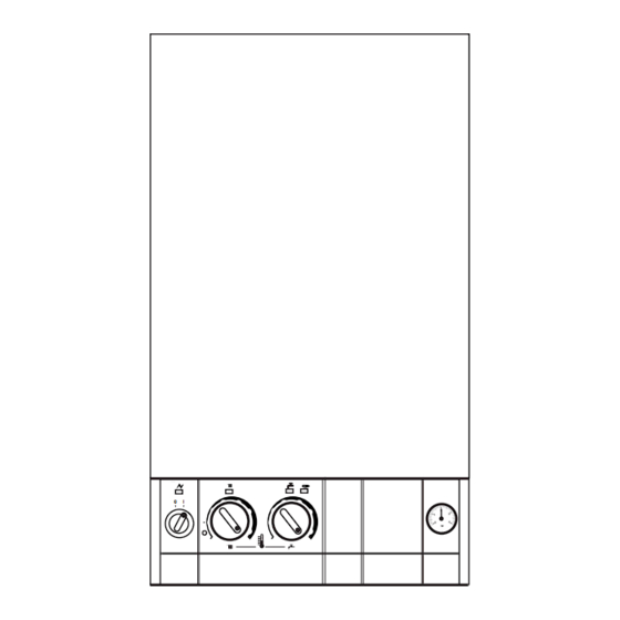
- Page 60 Temperature Control: The Central Heating water temperature is controlled by the centre knob on the facia. The Domestic Hot Water Temperature is controlled by the right hand knob on the facia. Standard Programme: To return to the standard programme press the SELECT and + buttons together. TO LIGHT AND STOP THE APPLIANCE Refer to the User operating instruction leaflet or the lighting instruction plate on the appliance.
- Page 61 Worcester Heat Systems Limited, Cotswold Way, Warndon, Worcester WR4 9SW. Telephone: (01905) 754624. Fax: (01905) 754619. Technical Helpline (0990) 266241 This booklet is accurate at the date of printing but will be superseded and should be disregarded if specifications and/or appearances are changed in the interests of continued improvement.
Need help?
Do you have a question about the 28Si and is the answer not in the manual?
Questions and answers
how do i top up the pressure gauge
To top up the pressure gauge on a Worcester 28Si boiler, follow these steps:
1. Locate the filling loop. This is usually a silver, flexible hose with a valve at each end, connecting the mains water supply to the boiler.
2. Make sure the boiler is turned off and the system is cool.
3. Slowly open both valves on the filling loop. You should hear water flowing.
4. Watch the pressure gauge on the boiler. When it reaches around 1.0 to 1.5 bar, close both valves.
5. If the pressure gauge does not move, the gauge might be stuck or there may be a fault with the filling loop valve.
6. If the system pressure exceeds 2.65 bar when hot, an extra expansion vessel may be required.
Always close the valves tightly after topping up and check for leaks.
This answer is automatically generated