
Related Manuals for Satlink FB250

Summary of Contents for Satlink FB250
- Page 1 FB250 INSTALLATION MANUAL...
- Page 2 Installation of Satlink Maritime FB 250 1 General The FB250 User Equipment (UE) is a maritime broadband system, providing simultaneous high-speed data and voice communication via satellite through the Inmarsat FleetBroadband system Applications include: Internet browsing E-mail Phone and fax services ...
- Page 3 55°C. The UE can be placed in a accessible area if the maximum ambient temperature does not exceed 55°C. For more information on installation, refer to the installation section of the FB250 User Equipment User’s Guide.
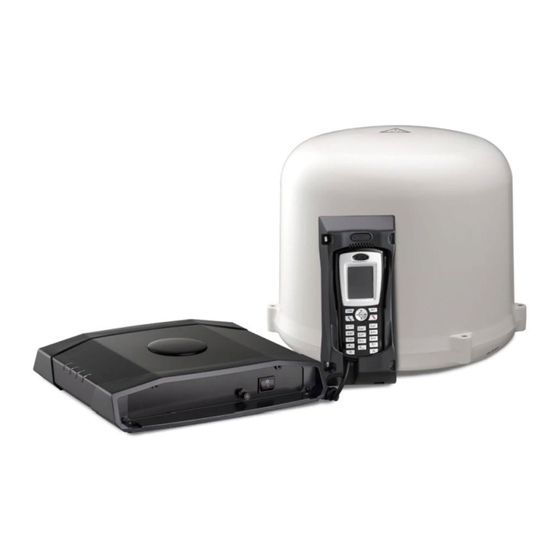
- Page 4 1 This kit include: On this Satlink FB 250 Equipment you can find next on the package: 1.- Satlink FB 250 Antenna (Satlink Ref: ) 2.- Satlink BDU 250 Unit (Satlink Ref: ) 3.- Primary Handset and Cradle (Satlink Ref: ) 4.- Power cable (Satlink Ref: )
- Page 5 RF unit and unit boards for communication and stabilized the antenna. Primary Handset + Cradle The Satlink FB250 has a dedicated RJ-45 port for connecting the Primary Handset, this is a special RJ-45 port to communicate the BDU with the Handset.
- Page 6 The cable between the terminal and antenna can be extended if it complies with the specified data concerning cable losses etc. All cables for the FB250 FleetBroadband system are shielded and should not be affected by magnetic fields. However, try to avoid running cables parallel to AC wiring as it might cause malfunction of the equipment.
- Page 7 3.1 Characteristics of “Pole Mount Kit” The installation is based on a “Pole Mount Kit” supplied by Satlink. Installation using the “Pole Mount Kit” is shown in Annex A. The kit consists of the following components and can be purchased from Satlink: 1pcs.
- Page 8 Washers, Part No. SPAC-M90-10062 are used to protect the plastic bushings SPAC- M00227 when the screws SPAC-M90-10102 are tightened to the specified torque (refer to Annex A). The washers MUST be used. Screws, Part No. SPAC-M90-10102 are M6 (metric), 25mm long screws made from stainless steel (A4) are used for fastening the antenna to the flange on the Mounting Pole so that the installation will endure vibrations and heavy loads due to wind or surges from rough sea.
-
Page 9: Installation Details
3.3 Alternative installation kits Satlink can assist in designing alternative Mounting Kits in case it should be needed e.g. in places where space is limited. Any new design should take into consideration the functional requirements listed in 2. - Page 10 ADU Mounting Base N-Type Receptacle Important notes to be followed before installing ADU The following notes shall be observed: The location of the ADU has to be kept away from the beam width of any search or tracking radar, which transits radiating power. With reference to the illustration, there are recommended mounting positions of the ADU where they are kept away from the red region area of the beam width.
- Page 11 Recommended positions of ADU Radar Beam Width Position 1 Position 2 Position 3 15° R A D A R 15° The line of sight to satellites of the ADU shall not be obstructed by any large obstacle in a vessel or ship. This will result in the degradation of the satellite signal.
- Page 12 104 cm 20 m • Upper deck of ship and ship’s funnels • VSAT • Large mechanical structure mounting of any radar...
- Page 13 For the safety reason, all personnel has to keep away at least 1-meter from the ADU. On the FB250 FleetBroadband System, the minimum safety distance on the focal line to the antenna panel is 0.6m, based on a radiation level of 10 W/m2. The radiation level is 100 W/m2 at a distance of 0.2m from the antenna panel.
- Page 14 • The physical size of the mast shall support the weight of ADU at 3.8kg and the physical dimension of Ø319.5mm with height of 277mm. An example of the antenna mast is illustrated as below. Antenna Mast • The mast should provide the internal hole for the installation of the antenna cable •...
- Page 15 ADU Mounting Base Cut-hole Dimension for flange Note: In case of the existing mast’s flange in a vessel or ship does not fit the ADU’s mounting base’s holes, a custom-made mechanical adaptation flange is to be designed and plate, which acts as an interface between the existing mast and the ADU.
-
Page 16: Antenna Dimensions
ERS Installation Manual. Mounting of ADU on Long Pole The physical dimension of a long pole shall be preferably at 2 meter height with its diameter ranges from Ø35 to Ø 50mm. In addition, the standard pole mount kit must be used for the installation of the ADU onto the long post. - Page 17 FB250 Installation Manual. 4 Installation Guide BDU The BDU is the controlling unit for the FB250 FleetBroadband system. It contains all user interfaces, LED indicators and stores configuration data. The built-in Web Console is used for easy configuration and daily use. The Web Console is accessed from a computer connected to the terminal, using an Internet browser.
- Page 18 Call/Message 4.1 Powering the BDU Satlink FB250 BDU unit can use a power input since 10 to 32 Vcc and more specifications are mentioned above. You should have in mind this picture to power the unit where the polarity is...
- Page 19 FB250 Installation Manual. If a 24 VDC power bus is not available, an external 115/230 VAC to 24 VDC power supply can be used. 4.2 Powering the BDU 4.3 Placing the BDU When placing the BDU having it's important to consider:...
-
Page 20: Installing The Handset
Connect the power supply to the AC outlet on the vessel. 4.5 Installing the handset Satlink FB250 comes with a cradle to place the handset while is not in use, the cradle can be secured either on a wall or placed on a desk. - Page 21 FB250 Installation Manual. 4.6 BDU Connections Front Panel Power button Circuit breaker Rear Connector Panel DC Power Connector Earth Grounding Stud Antenna Cable (Co-Axial) Connector...
- Page 22 Primary Handset Port Expansion Slot 5 Primary Handset This is the Primary Handset simple design colour screen unit The Handset has been design for Satlink FB250 Unit. Size is : 14 x 6 x 3 cm Weight is: 80 gr. (1) Earpiece...
-
Page 23: Using Simcard
*The speaker is located at the back of the Primary Handset. 6 Starting up the FB250 6.1 Using SIMCard The FB250 UE requires a dedicated FleetBroadband SIM card to access the FleetBroadband network and configure the settings of the UE. Please refer to your Airtime Service Provider for more information. -
Page 24: Switching On The Equipment
FB250 Installation Manual. Install the screw to secure the SIM card protection cover. 6.2 Switching On the Equipment Power Switch To switch on the UE, use the Power Switch on the UE front panel. When the UE is switched on, the Power LED indicator on the terminal lights up green. -
Page 25: Using The Web Console
On a computer connected to the terminal, open your browser and type http://192.168.1.35 in the Address field and press Enter. The Login screen appears. Type in admin in the Username field and satlink in the password field. Click OK. Click Settings on the Web Console. - Page 26 LAN connector on the UE. To check the connection, open your browser and type http://192.168.1.35 in the Address field and press Enter. The Login screen appears. Type in satlink in the Username field and satlink in the password field. Click OK.
- Page 27 FB250 Installation Manual.
-
Page 28: Led Indication
FB250 Installation Manual. 6.5 LED Indication Power ADU / GPS BGAN network Call/Message The LED gives information about the status of the BDU during the diferent stages of the initialization Action LED 2 LED 3 LED 4 Termi ADU/GPS BGAN Call&Message... - Page 29 (slow) Green Registering with the FleetBroadband Network When the UE accepts the SIM PIN, the FB250 system starts the registration procedure with the FleetBroadband network. You can monitor the registration procedure by looking at the Antenna and Terminal indicators on the LED panel of the UE.
- Page 30 Warning: All the settings and user data (e.g., Phone Book, GPS, etc.) of the FB250 UE will be cleared and reset to the default settings. If you do not wish to lose critical user data such as Phone...
-
Page 31: Firmware Upgrade
FB250 Installation Manual. Enter the Security code 0000 and click Factory Reset. 7.2 Firmware upgrade Firmware upgrade is to update your FB250 UE with the latest firmware. Please refer to your respective distributor for your firmware download. Warning: DO NOT abort the upgrading process or unplug the power of the FB250 UE during the firmware upgrade process at any time. - Page 32 FB250 Installation Manual. Select the downloaded new firmware and click Start. Firmware upgrade will take approximately 10 to 12 minutes to complete. You will be prompted with the Result: Firmware Upgrade Completed message.
-
Page 33: Safe Mode
FB250 Installation Manual. Click Reboot Terminal to reboot the FB250 UE. 7.3 Safe mode Safemode provides a protected environment to apply changes to the FB-250. The following actions are available from the safe mode menu • Firmware upgrade • Factory reset •... - Page 34 FB250 Installation Manual. GPS output This option allows to configure the NMEA port either as GPS output or as debug channel for servicing purposes 8 Troubleshooting and basic errors The ADU is steady red Tight the antenna cable to the BDU Network LED is steady amber Check with yout provider that the SIM card is active.
- Page 35 FB250 Installation Manual. How many primary PDP can I have at the same time Satlink FB250 is designed to have one primary PDP but multiple secondaries PDP How many secondary PDP can I have at the same time The maximum streaming allowed in a FB-250 is 128 kbps, therefore you can have as...
- Page 36 FB250 Installation Manual. TECHNICAL SPECS Satlink FB250 Rounter LAN/Ethernet: 4 x 10Base-T Ethernet Ports including 2 Power over Ethernet (PoE) LAN/Standard: IEEE 802.3 10Base-T Ethernet LAN/Network Protocols: TCP/IP, NAT, PAT, HTTP, DHCP Server, MAC address permission/rejection LAN/Cabling & onnector: RJ45 / Cat. 5, UTP, 100 meters max LAN/LED Indicator: Link/Act &...
- Page 37 FB250 Installation Manual. 5-20 Hz………….0.02G²/Hz 20-150 Hz……….-3dB/octave Vibration / Survival: Random vibration of 1.7g rms for a period of two hours in each of three mutually perpendicular axes (six hours total). 1.70 Grms with the following spectral density: 5-20 Hz………….0.05G²/Hz 20-150 Hz……….-3dB/octave...
Need help?
Do you have a question about the FB250 and is the answer not in the manual?
Questions and answers