Harman Kardon AVR340 Service Manual
7 x 55w 7.1 channel a/v receiver
Hide thumbs
Also See for AVR340:
- Service manual (85 pages) ,
- Owner's manual (68 pages) ,
- Brochure (6 pages)
Table of Contents
Advertisement
harman/kardon
7 X 55W 7.1 CHANNEL A/V RECEIVER
ESD WARNING.....................................2
LEAKAGE TESTING...............................3
BASIC SPECIFICATIONS.......................4
PACKAGING........................................5
Front Panel Controls.....................6
Rear Panel Connections................9
REMOTE CONTROL FUNCTIONS..........12
CONNECTIONS..................................16
Operation.......................................19
Troubleshooting Guide.................26
Processor Reset............................26
BULLETIN HK2006-01...........................27
AVR340
SERVICE MANUAL
CONTENTS
harman/kardon, Inc.
250 Crossways Park Dr.
Woodbury, New York 11797
TECH TIP HK2003-01............................28
Disassembly....................................29
UNIT EXPLODED VIEW..........................32
Exploded View PARTS LIST...............33
AMP BIAS ADJUSTMENT......................34
Block Diagram................................35
Electrical Parts List....................36
PCB DRAWINGS.................................80
SEMICONDUCTOR PINOUTS................86
SCHEMATICS.....................................178
Wiring Diagram..............................186
Rev 0 3/2006
Advertisement
Table of Contents

Related Manuals for Harman Kardon AVR340


Summary of Contents for Harman Kardon AVR340
-
Page 1: Service Manual
AVR340 7 X 55W 7.1 CHANNEL A/V RECEIVER SERVICE MANUAL CONTENTS ESD WARNING……………………………….2 TECH TIP HK2003-01…...….….………..…28 LEAKAGE TESTING……………….…..…..3 DISASSEMBLY………………………………29 BASIC SPECIFICATIONS…………………..4 UNIT EXPLODED VIEW……………………..32 PACKAGING………………………..………..5 EXPLODED VIEW PARTS LIST……………33 FRONT PANEL CONTROLS………..…..…..6 AMP BIAS ADJUSTMENT………………….34 REAR PANEL CONNECTIONS………….…9 BLOCK DIAGRAM…………………………..35 REMOTE CONTROL FUNCTIONS.………12... - Page 2 AVR340 harman/kardon Some semiconductor (solid state) devices can be damaged easily by static electricity. Such components commonly are called Electrostatically Sensitive (ES) Devices. Examples of typical ES devices are integrated circuits and some field effect transistors and semiconductor "chip" components.
- Page 3 AVR340 harman/kardon SAFETY PRECAUTIONS The following check should be performed for the continued protection of the customer and service technician. LEAKAGE CURRENT CHECK Measure leakage current to a known earth ground (water pipe, conduit, etc.) by connecting a leakage current tester...
- Page 4 AVR340 harman/kardon AVR 340 TECHNICAL SPECIFICATIONS Audio Section AM Tuner Section Stereo Mode Frequency Range 520–1720kHz Continuous Average Power (FTC) Signal-to-Noise Ratio 45dB Usable Sensitivity Loop 500µV 70 Watts per channel, 20Hz–20kHz, Distortion 1kHz, 50% Mod 0.8% @ <0.07% THD, both channels driven into 8 ohms Selectivity ±10kHz, 30dB...
- Page 5 AVR340 harman/kardon RH18Z00 RB30L00 AVR 340 RB30L00...
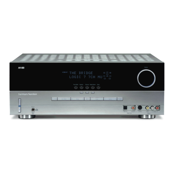
- Page 6 AVR340 harman/kardon FRONT-PANEL CONTROLS FRONT-PANEL CONTROLS ˜ ˆ ı Ù Û Ú Ò DIGITAL LOGIC 7 VID 1 PRO LOGIC VID 2 3 STEREO VID 3 FMAM HEADPHONE 5 7 CH. STEREO VID 4 TAPE 6 8 CH SURR. OFF...
- Page 7 AVR340 harman/kardon FRONT-PANEL CONTROLS FRONT-PANEL CONTROLS 6 Speaker Selector: Press this button to begin Ó Video 4 Video Input Jacks: These jacks may ‹ › Buttons: When configuring the AVR 340’s the process of configuring the unit to match the type...
- Page 8 AVR340 harman/kardon FRONT-PANEL CONTROLS (See page 46 for more information on reassigning the surround back speakers for multiroom use.) The letters inside each box display the active input channels. For standard analog sources, only the L and R will light, indicating a stereo input. For a digital source, the indicators will light to display the channels being received at the digital input.
- Page 9 AVR340 harman/kardon REAR-PANEL CONNECTIONS The Bridge F G H NOTE: To make it easier to follow the instructions that refer to this illustration, a larger copy may be downloaded from the Product Support section for this product at www.harmankardon.com. U Video 2 S-Video Input ¡...
- Page 10 AVR340 harman/kardon REAR-PANEL CONNECTIONS the remote room. See page 46 for more information and black terminals are the surround back right posi- operation of the unit and to avoid possible damage to on multiroom operation. tive (+) and negative (–) terminals. For multiroom use,...
- Page 11 AVR340 harman/kardon REAR-PANEL CONNECTIONS REAR-PANEL CONNECTIONS i Video 1 S-Video Input: If the product connected to NOTE: Thanks to the AVR 340’s cross-conversion NOTE ON VIDEO CONNECTIONS: When connecting the Video 1 Audio Inputs a has S-video capability, capability, if your video display device is equipped with...
-
Page 12: Main Remote Control Functions
AVR340 harman/kardon MAIN REMOTE CONTROL FUNCTIONS a Power Off Button b IR Transmitter Window c Program Indicator d Power On Button e Input Selectors f AVR Selector POWER g AM/FM Tuner Select MUTE h Dim Button i Test Button j Sleep Button... - Page 13 AVR340 harman/kardon MAIN REMOTE CONTROL FUNCTIONS IMPORTANT NOTE: The AVR 340’s remote may h Dim Button: Press this button to activate the Buttons: These multipurpose buttons are ⁄ ¤ be programmed to control up to seven devices, Dimmer function, which reduces the brightness of the used to change or scroll through items in the on- including the AVR 340.
- Page 14 AVR340 harman/kardon MAIN REMOTE CONTROL FUNCTIONS u Tuning Up/Down: When the tuner is in use, these When the remote is used to control the AVR, or the the desired station, and then press this button. Two VID2 or VID3 device, by default these buttons are pro-...
- Page 15 AVR340 harman/kardon MAIN REMOTE CONTROL FUNCTIONS compatible VCR, DVD or satellite receiver, pressing this button will switch between the output of the device and the external video input. Consult the owner’s man- ual for your specific player or receiver for the details of how it implements this function.
-
Page 16: System Installation
AVR340 harman/kardon INSTALLATION AND CONNECTIONS INSTALLATION AND CONNECTIONS the matching digital input connections on a CD-R or installer or a licensed electrician who is familiar with System Installation MiniDisc or other digital recorder. the NEC and/or the applicable local building codes in After unpacking the unit, locating it in a place with ade- your area. -
Page 17: Installation And Connections
AVR340 harman/kardon INSTALLATION AND CONNECTIONS recorder to take advantage of the fact that the 7. If both your video display monitor and at least one the audio, video and digital audio outputs of that device to the Video 4 Inputs *(ÓÔ on the... -
Page 18: System And Power Connections
AVR340 harman/kardon INSTALLATION AND CONNECTIONS System and Power Connections Option 2: Connect the Multiroom Audio Outputs Contact your dealer or visit www.harmankardon.com ™ on the AVR 340 to the inputs of an optional for more information on other A-BUS products The AVR 340 is designed for flexible use with multi- stereo power amplifier. - Page 19 AVR340 harman/kardon OPERATION OPERATION Outputs F, and they may be viewed on a video Basic Operation appear in the Lower Display Line ı . After a few display with component video inputs. seconds, the message will disappear and the dis- Once you have completed the initial setup and configu- play will return to half-brightness.
-
Page 20: Surround Mode Selection
AVR340 harman/kardon OPERATION • To temporarily silence all speaker outputs, press encoding processes, such as Dolby Surround or DTS be selected when a digital input is in use and a digital the Mute Button f¬. This will interrupt the Stereo, may be played in either the Dolby Digital, Dolby signal in that format is present. -
Page 21: Digital Audio Playback
AVR340 harman/kardon OPERATION ers are capable of reproducing low frequencies, and doubt as to the capability of your DVD player to handle When the unit senses PCM data from CDs or LDs, when you wish to hear the analog source material in DTS discs, consult the player’s owner’s manual. - Page 22 AVR340 harman/kardon OPERATION The information in the right side of the display will It is always a good idea to check the readout for the tell you if the digital audio data contains a special flag channel data to make certain that it matches the audio...
-
Page 23: Tuner Operation
AVR340 harman/kardon OPERATION The boxes around the channel indication letters are • Some television system broadcasters are not capa- indication will momentarily appear when an AM or used to show which speakers are configured in your ble of transmitting a 5.1 digital signal. Therefore, monaural FM station is tuned. - Page 24 AVR340 harman/kardon OPERATION OPERATION Recording The front-panel controls may be used to access a Then press the Set Button p to display the number of iPod functions. Press the Tuner Mode MANUAL SETUP submenu, and use the In normal operation, the audio or video source Button &...
- Page 25 AVR340 harman/kardon OPERATION Simply press the Dim Button h once to dim the front panel to half the normal brightness level; press it again to turn the displays off. Note that when the displays are dimmed or turned off, the blue Power Indicator 2 will remain lit as a reminder that the AVR is still turned on.
-
Page 26: Troubleshooting Guide
AVR340 harman/kardon TROUBLESHOOTING GUIDE SYMPTOM CAUSE SOLUTION Unit does not function when Main • No AC Power • Make certain AC power cord is plugged into Power Switch is pushed a live outlet • Check to see whether outlet is switch-controlled Display lights, but no sound •... - Page 27 AN0036-02200 * Note: For the models above, excluding the AVR340, the full On Screen Display (OSD) normally will not be visible with Component video connections alone. For model AVR340, when the component video jacks are used, the onscreen menus are not visible with high-definition video (720p or 1080i), and you must switch to the standard composite or S-video input on your TV, or to a 480p video source, to view them.
- Page 28 AVR340 harman/kardon TECH TIPS harman/kardon Troubleshooting tips and solutions to common service problems TIP# HKTT2003-01 Rev7 For models: AVR7000/7200/7300/8000 AVR10 AVR100/200/300/500 DPR1001 AVR110/210/310/510 DPR1005 AVR120/220/320/520 DPR2005 AVR125/225/325/525 HK3370/3470/3375/3475 AVR130/230/330/430/630 HK3250 AVR135/235/335/435/635 AVR140/240/340 Subject: Backup Memory on AVR/DPR/HK series receivers In the event of the complaint: “the receiver is losing its memory (any programmed system settings) when the unit is turned off, or after the unit is unplugged (briefly*)”:...
- Page 29 AVR340 harman/kardon...
- Page 30 AVR340 harman/kardon DISASSEMBLY PROCEDURES(AVR340) <1> TOP-CABINET(21) REMOVAL 1. Remove 13 screws(S1,S7) and then remove the Top-cabinet. <2> FRONT PANEL ASS’Y REMOVAL 1. Remove the Top-cabinet, referring to the previous step<1>. 2. Disconnect the lead wire (BN72-32p)) on the Fip PCB(37-1) from connector(CN72) on the Input PCB(39-1) 3.
- Page 31 AVR340 harman/kardon <8>VIDEO PCB(40-1) REMOVAL 1. Remove the Top-cabinet, referring to the previous step<1>. 2. Disconnect the lead wire(BN41-6P) on the Tone PCB(37-3) from connector(CN41) on the Video PCB(40-1 3.Disconnect the connector (CN15-Card cable) on the Input PCB(39-1) from connector(CN43) on the Video PCB(40-1).
- Page 32 REFER TO PARTS LIST NEXT PAGE...
- Page 33 AVR340 harman/kardon...
- Page 34 AVR340 harman/kardon AMPLIFIER SECTION BIAS ADJUSTMENT Measurement condition . No input signal or volume position is minimum. Standard value. ± . Ideal current = 48mA ( ± . Ideal DC Voltage = 25.92mV ( CUP11816Z (VIDEO PCB) .... CN82...
- Page 35 AVR340 harman/kardon...
- Page 36 AVR340 harman/kardon AVR340 Electrical Parts List Ref. Designator Part Number Description FRONT PCB ASSY (CUP11818Y) Capacitors C703 HCBS1H821KBT CAP , CERAMIC 820PF 50V K C704 CCEA1VH100T CAP , ELECT 10UF 35V C712 CCEA1HH1R0T CAP , ELECT 1UF 50V C713 HCBS1H223ZFT CAP , CERAMIC 0.022UF 50V Z...
- Page 37 AVR340 harman/kardon Ref. Designator Part Number Description FRONT PCB ASSY (CUP11818Y) Q701 HVTKRC107MT TRANSISTOR KRC107M Q702 HVTKRA107MT TRANSISTOR KRA107M Q705 HVTKRC107MT TRANSISTOR KRC107M Q722 HVTKRA107MT TRANSISTOR KRA107M Q724 HVTKRC107MT TRANSISTOR KRC107M Q725 HVTKRC107MT TRANSISTOR KRC107M Q726 HVTKRC107MT TRANSISTOR KRC107M Q727...
- Page 38 AVR340 harman/kardon Ref. Designator Part Number Description FRONT PCB ASSY (CUP11818Y) R782 CRD20TJ103T RES , CARBON 10K OHM 1/5W J R786 CRD20TJ152T RES , CARBON 1.5K OHM 1/5W J R787 CRD20TJ101T RES , CARBON 100 OHM 1/5W J R789 CRD20TJ102T...
- Page 39 AVR340 harman/kardon Ref. Designator Part Number Description PCB , POWER KEY (CUP11818-6) CN88 CJP04GA19ZY WAFER, STRAIGHT, 4PIN WIRE D723 CVD50BOBBWGA L.E.D , 2 COLOR (ORG , BLUE) L.E.D S701 HST1A020ZT SW , TACT 1A020 PCB , DIGITAL INPUT (FRONT) (CUP11818-8)
- Page 40 AVR340 harman/kardon Ref. Designator Part Number Description PCB , FRONT PANEL KEY (CUP11818-2) Miscellaneous BN89 CWB2B905080EN WIRE ASS'Y WIRE S702 HST1A020ZT SW , TACT 1A020 S703 HST1A020ZT SW , TACT 1A020 S704 HST1A020ZT SW , TACT 1A020 S705 HST1A020ZT SW , TACT...
- Page 41 AVR340 harman/kardon Ref. Designator Part Number Description PCB , VOLUME ENCODER (CUP11818-3) R878 CRD20TJ750T RES , CARBON 75 OHM 1/5W J Miscellaneous BN10 CWZAVR230BN10 WIRE ASS'Y (SHIELD) WIRE BN41 CWZAVR130BN41 WIRE ASS'Y (SHIELD) WIRE CN84 KJP05GB46ZM WAFER WIRE JK85 CJJ9M003Z...
- Page 42 AVR340 harman/kardon Ref. Designator Part Number Description INPUT PCB (CUP11815-1) C219 HCUS1H221JA CAP , CHIP 220PF C220 HCUS1H221JA CAP , CHIP 220PF C221 HCUS1H221JA CAP , CHIP 220PF C222 HCUS1H221JA CAP , CHIP 220PF C223 HCUS1H221JA CAP , CHIP 220PF...
- Page 43 AVR340 harman/kardon Ref. Designator Part Number Description INPUT PCB (CUP11815-1) C351 HCUS1H332KC CAP , CHIP 3300PF C352 HCUS1H332KC CAP , CHIP 3300PF C353 HCUS1H332KC CAP , CHIP 3300PF C354 HCUS1H332KC CAP , CHIP 3300PF C355 HCUS1H332KC CAP , CHIP 3300PF...
- Page 44 AVR340 harman/kardon Ref. Designator Part Number Description INPUT PCB (CUP11815-1) C551 HCUS1H104ZF CAP , CHIP 0.1UF C552 HCUS1H104ZF CAP , CHIP 0.1UF C553 HCUS1H103KC CAP , CHIP 0.01UF C556 HCUS1H220JA CAP , CHIP 22PF C557 HCUS1H220JA CAP , CHIP 22PF...
- Page 45 AVR340 harman/kardon Ref. Designator Part Number Description INPUT PCB (CUP11815-1) C756 HCUS1H104ZF CAP , CHIP 0.1UF C757 HCUS1H104ZF CAP , CHIP 0.1UF C758 HCUS1H104ZF CAP , CHIP 0.1UF C759 HCUS1H104ZF CAP , CHIP 0.1UF C760 HCUS1H104ZF CAP , CHIP 0.1UF...
- Page 46 AVR340 harman/kardon Ref. Designator Part Number Description INPUT PCB (CUP11815-1) C460 CCEA1VH100T CAP , ELECT 10UF 35V C522 CCEA1CH101T CAP , ELECT 100UF 16V C524 CCEA1CH101T CAP , ELECT 100UF 16V C542 CCEA1HH2R2T CAP , ELECT 2.2UF 50V C545 CCEA1HH2R2T CAP , ELECT 2.2UF 50V...
- Page 47 AVR340 harman/kardon Ref. Designator Part Number Description INPUT PCB (CUP11815-1) IC35 HVINJM2068MDTE1 I.C , OP AMP (NJM2068) IC36 HVINJM2068MDTE1 I.C , OP AMP (NJM2068) IC37 HVINJM2068MDTE1 I.C , OP AMP (NJM2068) IC42 HVITC9459BFG I.C , 2CH VOLUME (TC9459BFG) TOSHIBA IC43 HVITC9482BFG I.C , 6CH VOLUME (TC9482BFG)
- Page 48 AVR340 harman/kardon Ref. Designator Part Number Description INPUT PCB (CUP11815-1) RN79 CRJ104DJ101T RES, ARRAY, 100R (1608) 100 OHM/1608*4 RN80 CRJ104DJ330T RES , 4ARRAY (1608*4) 33 OHM/1608*4 RN81 CRJ104DJ330T RES , 4ARRAY (1608*4) 33 OHM/1608*4 RN82 CRJ104DJ330T RES , 4ARRAY (1608*4)
- Page 49 AVR340 harman/kardon Ref. Designator Part Number Description INPUT PCB (CUP11815-1) R243 CRJ10DJ474T RES, CHIP 470K OHM R244 CRJ10DJ474T RES, CHIP 470K OHM R245 CRJ10DJ474T RES, CHIP 470K OHM R246 CRJ10DJ474T RES, CHIP 470K OHM R247 CRJ10DJ474T RES, CHIP 470K OHM...
- Page 50 AVR340 harman/kardon Ref. Designator Part Number Description INPUT PCB (CUP11815-1) R318 CRJ10DJ101T RES , CHIP 100 OHM R319 CRJ10DJ101T RES , CHIP 100 OHM R320 CRJ10DJ101T RES , CHIP 100 OHM R321 CRJ10DJ512T RES , CHIP 5.1K OHM R322 CRJ10DJ122T RES , CHIP 1.2K OHM...
- Page 51 AVR340 harman/kardon Ref. Designator Part Number Description INPUT PCB (CUP11815-1) R395 CRJ10DJ153T RES , CHIP 15K OHM R396 CRJ10DJ332T RES , CHIP 3.3K OHM R397 CRJ10DJ101T RES , CHIP 100 OHM R398 CRJ10DJ101T RES , CHIP 100 OHM R403 CRJ10DJ184T...
- Page 52 AVR340 harman/kardon Ref. Designator Part Number Description INPUT PCB (CUP11815-1) R496 CRJ10DJ4R7T RES , CHIP 4.7 OHM R497 CRJ10DJ4R7T RES , CHIP 4.7 OHM R498 CRJ10DJ4R7T RES , CHIP 4.7 OHM R551 CRJ10DJ102T RES , CHIP 1K OHM R552 CRJ10DJ102T...
- Page 53 AVR340 harman/kardon Ref. Designator Part Number Description INPUT PCB (CUP11815-1) R771 CRJ10DJ330T RES , CHIP 33 OHM R772 CRJ10DJ330T RES , CHIP 33 OHM R773 CRJ10DJ103T RES , CHIP 10K OHM R774 CRJ10DJ330T RES , CHIP 33 OHM R775 CRJ10DJ103T...
- Page 54 AVR340 harman/kardon Ref. Designator Part Number Description INPUT PCB (CUP11815-1) JK14 CJJ4R019W TERMINAL , IN/OUT TERMINAL JACK JK15 CJJ4R037W JACK , BOARD JACK JW21 CWE7202090AA WIRE ASS'Y WIRE L561 HLQ02CR68KT COIL , AXAIL 0.68UH L563 HLQ02CR39KT COIL , AXAIL 0.39UH...
- Page 55 AVR340 harman/kardon Ref. Designator Part Number Description MUTI-ROOM & A-BUS PCB (CUP11815-2) R431 CRJ10DJ122T RES , CHIP 1.2K OHM R432 CRJ10DJ122T RES , CHIP 1.2K OHM R441 CRJ10DJ101T RES , CHIP 100 OHM R442 CRJ10DJ101T RES , CHIP 100 OHM...
- Page 56 AVR340 harman/kardon Ref. Designator Part Number Description VIDEO PCB (CUP11849-1) C418 HCBS1H223ZFT CAP , CERAMIC 0.022UF 50V Z C419 CCEA1VH100T CAP , ELECT 10UF 35V C420 HCBS1H223ZFT CAP , CERAMIC 0.022UF 50V Z C421 CCEA1CH101T CAP , ELECT 100UF 16V...
- Page 57 AVR340 harman/kardon Ref. Designator Part Number Description VIDEO PCB (CUP11849-1) C556 CCEA1CH101T CAP , ELECT 100UF 16V C557 CCEA1CH101T CAP , ELECT 100UF 16V C561 CCEA1CH101T CAP , ELECT 100UF 16V C568 HCBS1H104ZFT CAP , CERAMIC 0.1UF 50V Z C520...
- Page 58 AVR340 harman/kardon Ref. Designator Part Number Description VIDEO PCB (CUP11849-1) R417 CRD20TJ750T RES , CARBON 75 OHM 1/5W J R418 CRD20TJ750T RES , CARBON 75 OHM 1/5W J R419 CRD20TJ750T RES , CARBON 75 OHM 1/5W J R420 CRD20TJ332T RES , CARBON 3.3K OHM 1/5W J...
- Page 59 AVR340 harman/kardon Ref. Designator Part Number Description VIDEO PCB (CUP11849-1) R501 CRD20TJ102T RES , CARBON 1K OHM 1/5W J R502 CRD20TJ102T RES , CARBON 1K OHM 1/5W J R503 CRD20TJ102T RES , CARBON 1K OHM 1/5W J R504 CRD20TJ104T RES , CARBON...
- Page 60 AVR340 harman/kardon Ref. Designator Part Number Description COMPONENT PCB (CUP11849-2) C603 HCBS1H220JCT CAP , CERAMIC 22PF 50V J C604 HCBS1H220JCT CAP , CERAMIC 22PF 50V J C605 HCBS1H220JCT CAP , CERAMIC 22PF 50V J C606 HCBS1H220JCT CAP , CERAMIC 22PF 50V J...
- Page 61 AVR340 harman/kardon Ref. Designator Part Number Description DIGITAL IN/OUT PCB (CUP11849-13) C756 HCBS1H104ZFT CAP , CERAMIC 0.1UF 50V Z C757 HCBS1H104ZFT CAP , CERAMIC 0.1UF 50V Z C758 HCBS1H104ZFT CAP , CERAMIC 0.1UF 50V Z C759 HCBS1H101KBT CAP , CERAMIC...
- Page 62 AVR340 harman/kardon Ref. Designator Part Number Description POWER TRANS PCB (CUP11849-4,5) C120 CCEA1JH470TS CAP , ELECT 63V/47UF/105'C C121 CCKT1H103ZF CAP , CERAMIC 0.01UF 50V ZF C122 CCEA2AH101E CAP , ELECT 100UF C921 HCQI1H104JZT CAP , MYLAR 0.1UF 50V J C922...
- Page 63 AVR340 harman/kardon Ref. Designator Part Number Description POWER TRANS PCB (CUP11849-4,5) SW91 KST1A010Z SW , TACT CN SWITCH CMY1A219 HEAT SINK (BRIDGE DIODE) HEAT SINK CTB3+12J SCREW SCREW CMY1A219 HEAT SINK (BRIDGE DIODE) HEAT SINK CTB3+12J SCREW SCREW F903 KBA2C8000TLU FUSE 8.0A 250V...
- Page 64 AVR340 harman/kardon Ref. Designator Part Number Description BIAS & REGULATOR PCB (CUP11849-6,8) Resistors R874 CRD20TJ331T RES , CARBON 330 OHM 1/5W J R875 CRD20TJ331T RES , CARBON 330 OHM 1/5W J R876 CRD20TJ331T RES , CARBON 330 OHM 1/5W J...
- Page 65 AVR340 harman/kardon Ref. Designator Part Number Description MIC & HP PCB (CUP11849-9) C870 HCBS1H681KBT CAP , CERAMIC 680PF 50V C871 HCBS1H681KBT CAP , CERAMIC 680PF 50V C872 CCEA1CH331T CAP , ELECT 330UF 16V C873 CCEA1CH331T CAP , ELECT 330UF 16V...
- Page 66 AVR340 harman/kardon Ref. Designator Part Number Description MIC & HP PCB (CUP11849-9) R957 CRD20TJ101T RES , CARBON 100 OHM 1/5W J R958 CRD20TJ471T RES , CARBON 470 OHM 1/5W J Miscellaneous RL81 HSL4A011ZE RELAY OMI-SS-212L BN16 CWZAVR140BN16 WIRE ASS'Y (SHIELD)
- Page 67 AVR340 harman/kardon Ref. Designator Part Number Description IPOD PCB (CUP11834Y) C410 HCEC1HRV21R0T CAP , ELEC (SMD) 1UF/50 C411 HCEC1HRV21R0T CAP , ELEC (SMD) 1UF/50 C416 HCUS1H473ZF CAP , CHIP 0.047UF C421 HCUS1H471JA CAP , CHIP 470PF C422 HCUS1H471JA CAP , CHIP...
- Page 68 AVR340 harman/kardon Ref. Designator Part Number Description MAIN PCB (CUP11579W) C561 CCEA1CH101T CAP , ELECT 100UF 16V C562 CCEA1CH101T CAP , ELECT 100UF 16V C564 CCEA1CH101T CAP , ELECT 100UF 16V C566 CCEA1CH101T CAP , ELECT 100UF 16V C567 CCEA1CH101T...
- Page 69 AVR340 harman/kardon Ref. Designator Part Number Description MAIN PCB (CUP11579W) C914 HCQI1H473JZT CAP , MYLAR 0.047UF 50V J C917 HCQI1H473JZT CAP , MYLAR 0.047UF 50V J C918 HCQI1H473JZT CAP , MYLAR 0.047UF 50V J C919 HCQI1H473JZT CAP , MYLAR 0.047UF 50V J...
- Page 70 AVR340 harman/kardon Ref. Designator Part Number Description MAIN PCB (CUP11579W) D584 HVD1SS133MT DIODE 1SS133T D585 HVD1SS133MT DIODE 1SS133T D601 HVD1SS133MT DIODE 1SS133T D801 HVD1SS133MT DIODE 1SS133T D802 HVD1SS133MT DIODE 1SS133T D803 HVD1SS133MT DIODE 1SS133T D804 HVD1SS133MT DIODE 1SS133T D901 KVD1N4003ST...
- Page 71 AVR340 harman/kardon Ref. Designator Part Number Description MAIN PCB (CUP11579W) Q603 HVTKTA1268GRT TRANSISTOR KTA1268GR Q604 HVTKTA1268GRT TRANSISTOR KTA1268GR Q605 HVTKTA1268GRT TRANSISTOR KTA1268GR Q681 KVTKSC2785YT TRANSISTOR KSC2785Y Q682 KVTKSC2785YT TRANSISTOR KSC2785Y Q683 KVTKSC2785YT TRANSISTOR KSC2785Y Q684 KVTKSC2785YT TRANSISTOR KSC2785Y Q685 KVTKSC2785YT...
- Page 72 AVR340 harman/kardon Ref. Designator Part Number Description MAIN PCB (CUP11579W) Q993 HVTKRA107MT TRANSISTOR KRA107M Q994 HVTKRC107MT TRANSISTOR KRC107M Q652 HVT2SB1647-OKM TRANSISTOR, POWER 2SB1647 Q653 HVT2SB1647-OKM TRANSISTOR, POWER 2SB1647 Q654 HVT2SB1647-OKM TRANSISTOR, POWER 2SB1647 Q655 HVT2SB1647-OKM TRANSISTOR, POWER 2SB1647 Q657 HVT2SD2560-OKM...
- Page 73 AVR340 harman/kardon Ref. Designator Part Number Description MAIN PCB (CUP11579W) R533 CRD20TJ221T RES , CARBON 220 OHM 1/5W J R534 CRD20TJ221T RES , CARBON 220 OHM 1/5W J R535 CRD20TJ221T RES , CARBON 220 OHM 1/5W J R536 CRD20TJ221T RES , CARBON...
- Page 74 AVR340 harman/kardon Ref. Designator Part Number Description MAIN PCB (CUP11579W) R606 CRD20TJ223T RES , CARBON 22K OHM 1/5W J R607 CRD20TJ223T RES , CARBON 22K OHM 1/5W J R608 CRD20TJ223T RES , CARBON 22K OHM 1/5W J R609 CRD20TJ223T RES , CARBON...
- Page 75 AVR340 harman/kardon Ref. Designator Part Number Description MAIN PCB (CUP11579W) R705 CRD20TJ821T RES , CARBON 820 OHM 1/5W J R706 CRD20TJ821T RES , CARBON 820 OHM 1/5W J R707 CRD20TJ821T RES , CARBON 820 OHM 1/5W J R708 CRD20TJ821T RES , CARBON...
- Page 76 AVR340 harman/kardon Ref. Designator Part Number Description MAIN PCB (CUP11579W) R837 CRD20TJ561T RES , CARBON 560 OHM 1/5W J R838 CRD20TJ561T RES , CARBON 560 OHM 1/5W J R839 CRD20TJ561T RES , CARBON 560 OHM 1/5W J R840 CRD20TJ561T RES , CARBON...
- Page 77 AVR340 harman/kardon Ref. Designator Part Number Description MAIN PCB (CUP11579W) R934 CRD20TJ104T RES , CARBON 100K OHM 1/5W J R935 CRD20TJ154T RES , CARBON 150K OHM 1/5W J R936 CRD20TJ184T RES , CARBON 180K OHM 1/5W J R939 CRD20TJ472T RES , CARBON 4.7K OHM 1/5W J...
- Page 78 AVR340 harman/kardon Ref. Designator Part Number Description MAIN PCB (CUP11579W) R995 CRG1ANJ100H RES , METAL OXIDE FILM 10 OHM R996 CRG1ANJ100H RES , METAL OXIDE FILM 10 OHM R997 CRG1ANJ100H RES , METAL OXIDE FILM 10 OHM R999 CRG1ANJ100H RES , METAL OXIDE FILM...
- Page 79 AVR340 harman/kardon Ref. Designator Part Number Description MAIN PCB (CUP11579W) L504 CLEY0R5KAK COIL , SPEAKER 0.5UH L505 CLEY0R5KAK COIL , SPEAKER 0.5UH L506 CLEY0R5KAK COIL , SPEAKER 0.5UH L507 CLEY0R5KAK COIL , SPEAKER 0.5UH RY94 HSL1A008ZE RELAY SDT-S-112DMR TH91 KRTP42T7D330B...
- Page 80 AVR340 harman/kardon...
- Page 81 AVR340 harman/kardon...
- Page 82 AVR340 harman/kardon...
- Page 83 AVR340 harman/kardon...
- Page 84 AVR340 harman/kardon...
- Page 85 AVR340 harman/kardon...
-
Page 86: General Description
AVR340 harman/kardon November 1988 Revised November 1999 74AC04 • 74ACT04 Hex Inverter General Description Features The AC/ACT04 contains six inverters. reduced by 50% on 74AC only Outputs source/sink 24 mA ACT04 has TTL-compatible inputs Ordering Code: Order Number Package Number... - Page 87 AVR340 harman/kardon M54HCU04 M74HCU04 HEX INVERTER (SINGLE STAGE) HIGH SPEED = 5 ns (TYP.) AT V = 5 V LOW POWER DISSIPATION = 1 µA (MAX.) AT T = 25 C HIGH NOISE IMMUNITY = 10 % V (MIN.) OUTPUT DRIVE CAPABILITY...
- Page 88 AVR340 harman/kardon PIN ASSIGNMENT (74HCU04AFN : IC72,76 ) LOGIC SYMBOL (10) (11) (13) (12) TRUTH TABLE...
- Page 89 AVR340 harman/kardon Video Switch · 75Ω driver · Y/C mix MM1501 MITSUMI Video Switch · 75Ω driver · Y/C mix Monolithic IC MM1501 Series Outline This IC extends the series of ICs for video/audio signal switching, with a 2-input 1-output single video switch, video signal/chroma signal 75Ω...
- Page 90 AVR340 harman/kardon Video Switch · 75Ω driver · Y/C mix MM1501 MITSUMI MM1507 MM1508 MM1509 MM1510 MM1511 MM1512...
- Page 91 AVR340 harman/kardon Video Switch · 75Ω driver · Y/C mix MM1501 MITSUMI MM1509 Item Symbol Measurement conditions Min. Typ. Max. Unit Refer to measurement procedures Consumption current Refer to measurement procedures µA Current consumption for PS Refer to measurement procedures...
-
Page 92: Ordering Information
AVR340 harman/kardon HY57V161610ETP-I 2 Banks x 512K x 16 Bit Synchronous DRAM DESCRIPTION THE Hynix HY57V161610E is a 16,777,216-bits CMOS Synchronous DRAM, ideally suited for the main memory and graphic appli- cations which require large memory density and high bandwidth. HY57V161610E is organized as 2banks of 524,288x16. -
Page 93: Pin Description
AVR340 harman/kardon HY57V161610ETP-I PIN CONFIGURATION DQ15 DQ15 DQ14 DQ14 VSSQ VSSQ DQ13 DQ13 DQ12 DQ12 VDDQ VDDQ DQ11 DQ11 DQ10 DQ10 VSSQ VSSQ 50pin TSOP II 50pin TSOP II VDDQ VDDQ VDDQ VDDQ 400mil x 825mil 400mil x 825mil LDQM LDQM 0.8mm pin pitch... - Page 94 AVR340 harman/kardon HY57V161610ETP-I FUNCTIONAL BLOCK DIAGRAM 1Mx16 Synchronous DRAM Self Refresh Counter Refresh Refresh Interval Timer Counter 512Kx16 Bank 0 Address[0:10] Sense AMP & I/O gates Column Decoder Address Precharge Register Row Active BA(A11) Column Addr. Column Active Latch & Counter...
- Page 95 AVR340 harman/kardon HY57V161610ETP-I COMMAND TRUTH TABLE A10/ Command CKEn-1 CKEn A0~A9 Note Mode Register Set OP code No Operation Bank Active Row Address Read Column Address Read with Auto precharge Write Column Address Write with Auto precharge Precharge All Bank...
- Page 96 AVR340 harman/kardon March 1995 Revised February 2005 74LCX32 Low Voltage Quad 2-Input OR Gate with 5V Tolerant Inputs General Description Features The LCX32 contains four 2-input OR gates. The inputs tol- 5V tolerant inputs erate voltages up to 7V allowing the interface of 5V sys- 2.3V–3.6V V...
-
Page 97: Connection Diagrams
AVR340 harman/kardon Logic Symbol Connection Diagrams IEEC/IEC Pin Assignments for SOIC, SOP, and TSSOP Pin Descriptions Pin Names Description Pad Assignment for DQFN Inputs Outputs (Top View) - Page 98 AVR340 harman/kardon ASAHI KASEI [AK4589] AK4589 2/8-Channel Audio CODEC with DIR GENERAL DESCRIPTION The AK4589 is a single chip CODEC that includes two channels of ADC and eight channels of DAC. The ADC outputs 24bit data and the DAC accepts up to 24bit input data. The ADC has the Enhanced Dual Bit architecture with wide dynamic range.
- Page 99 AVR340 harman/kardon ASAHI KASEI [AK4589] DIR/DIT Part • AES3, IEC60958, S/PDIF, EIAJ CP1201 Compatible • Low jitter Analog PLL • PLL Lock Range : 32kHz to 192kHz • Clock Source: PLL or X'tal • 8-channel Receiver input • 2-channel Transmission output (Through output or DIT) •...
- Page 100 AVR340 harman/kardon ASAHI KASEI [AK4589] Block Diagram PVSS PVDD X'tal Clock Oscillator 8 to 3 Recovery Clock MCKO1 Generator Input MCKO2 Selector LRCK2 DAIF Audio BICK2 Decoder SDTO2 DAUX2 AVDD AVSS DVDD Error & CCLK Q-subcode DVSS AC-3/MPEG µP I/F...
- Page 101 AVR340 harman/kardon ASAHI KASEI [AK4589] Ordering Guide -10 ∼ +70°C AK4589VQ 80pin LQFP(0.5mm pitch) AKD4589 Evaluation Board for AK4589 Pin Layout TEST1 INT1 BOUT TVDD DVDD AVSS DVSS AVDD VREFH VCOM (Top View) TEST3 MCKO2 MCKO1 ROUT1+ COUT ROUT1- UOUT...
- Page 102 AVR340 harman/kardon ASAHI KASEI [AK4589] PIN/FUNCTION Pin Name Function INT1 Interrupt 1 Pin Block-Start Output Pin for Receiver Input BOUT “H” during first 40 flames. TVDD Output Buffer Power Supply Pin, 2.7V∼5.25V DVDD Digital Power Supply Pin, 4.75V∼5.25V DVSS Digital Ground Pin...
- Page 103 AVR340 harman/kardon ASAHI KASEI [AK4589] Pin Name Function Power-Down Mode Pin When “L”, the AK4589 is powered-down, all digital output pins go “L”, all registers are reset. When CAD1/0 pins are changed, the AK4589 should be reset by PDN pin.
- Page 104 AVR340 harman/kardon ASAHI KASEI [AK4589] Pin Name Function AVDD Analog Power Supply Pin, 4.75V∼5.25V Analog Ground Pin, 0V AVSS Receiver Channel 0 Pin (Internal biased pin. Internally biased at PVDD/2) No Connect pin No internal bonding. This pin should be connected to PVSS.
- Page 105 AVR340 harman/kardon CS49400 Family DSP Multi-Standard Audio Decoder Features Description CS49300 Legacy Audio Decoder Support The CS49400 Audio Decoder DSP is targeted as a market- specific consumer entertainment processor for AV Receivers Dolby Digital EX , Dolby Pro Logic II and DVD Audio/Video Players.
- Page 106 AVR340 harman/kardon ® 2. OVERVIEW • HDCD The CS49400 is a 24-bit fixed-point decoder DSP All of the above audio decoding/processing followed by a 32-bit fixed point programmable algorithms and the associated application notes post-processor DSP. The decoder portion of the (AN208 and their corresponding appendices) are CS49400 is referred to as “DSPAB”.
- Page 107 AVR340 harman/kardon ® ™ • Ultra2 Cinema 7.1 Channel 2.2 DSPC Post-Processor DSPC is a 32-bit, general-purpose, fixed-point ™ RAM-based processor which includes on-chip • Cirrus Extra Surround ROM tables. It has been designed with a generous ™ • Cirrus Original Multichannel Surround amount of on-chip program and data RAM, and has ™...
- Page 108 AVR340 harman/kardon from either an external microcontroller or through 3.2 Termination Requirements one of the boot procedures listed in Section 8. The CS49400 incorporates open drain pins which must be pulled high for proper operation. 3. TYPICAL CONNECTION DIAGRAMS FINTREQ and INTREQ are always open drains Four typical connection diagrams have been which requires a pull-up for proper operation.
- Page 109 AVR340 harman/kardon 4. POWER 4.2 Analog Power Conditioning The CS49400 requires a 2.5V digital power supply In order to obtain the best performance from the for the core logic and 2.5V I/O and a 2.5V analog CS49400’s internal PLL, the analog power supply power supply for the internal PLL.
- Page 110 AVR340 harman/kardon 12.0 PIN DESCRIPTION 12.1 144-Pin LQFP Package Pin Layout AUDATA1 SD_ADDR10, EXTA10 AUDATA0 SD_BA, EXTA19 CMPCLK, FSCLKN2 VDDSD1 HDATA2, GPIO2 VSSSD1 VSS3 SD_CS VDD3 SD_ADDR4, EXTA4 HDATA1, GPIO1 SD_ADDR5, EXTA5 HDATA0, GPIO0 SD_ADDR6, EXTA6 CMPREQ, FLRCLKN2 SD_CLK_EN CMPDAT, FSDATAN2...
- Page 111 AVR340 harman/kardon 12.2 100-Pin LQFP Package Pin Layout AUDATA1 EXTA10 AUDATA0 EXTA19 CMPCLK, FSCLKN2 VDDSD1 VSS3 VSSSD1 VDD3 EXTA4 CMPREQ, FLRCLKN2 EXTA5 CMPDAT, FSDATAN2 EXTA6 FLRCLKN1 EXTA7 PLLVSS EXTA8 FILT2 EXTA9 FILT1 EXTA11 PLLVDD EXTA12 XTALO EXTA13 CLKIN, XTALI EXTA14...
- Page 112 AVR340 harman/kardon 12.3 Pin Definitions FILT1 — Phase-Locked Loop Filter Connects to an external filter for the on-chip phase-locked loop. FILT2 — Phase Locked Loop Filter Connects to an external filter for the on-chip phase-locked loop. CLKIN, XTALI — External Clock Input/Crystal Oscillator Input CS49400 clock input.
- Page 113 AVR340 harman/kardon FA1, FSCDIN — Host Address Bit One or SPI Serial Control Data Input In parallel host mode, this pin serves as one of two address input pins used to select one of four parallel registers. In SPI serial host mode, this pin serves as the data input. INPUT FHS1, FRD, FR/W —...
- Page 114 AVR340 harman/kardon Digital-audio frame clock input. FLRCLKN1 typically is run at the sampling frequency. FLRCLKN1 operates asynchronously from all other DSPAB clocks. The polarity of FLRCLKN1 for a particular subframe can be programmed by the DSP. BIDIRECTIONAL - Default: INPUT FSDATAN1 —...
- Page 115 AVR340 harman/kardon This should be tied low for normal operation. INPUT MCLK — Audio Master Clock Bidirectional master audio clock. As an output, MCLK provides a low jitter oversampling clock. MCLK supports all standard oversampling frequencies. BIDIRECTIONAL - Default: INPUT SCLK0 —...
- Page 116 AVR340 harman/kardon CMOS level output that outputs a biphase-mark encoded (S/PDIF) IEC60958 signal or digital audio data which is capable of carrying two channels of PCM digital audio. OUTPUT AUDATA4, GPIO28 — Digital Audio Output 4, General Purpose I/O PCM digital-audio data output. This pin can act as a general-purpose input or output that can be individually configured and controlled by DSPC.
- Page 117 AVR340 harman/kardon Digital-audio PCM data input. This pin can act as a general-purpose input or output that can be individually configured and controlled by DSPC. BIDIRECTIONAL - Default: INPUT SDATAN2, GPIO26 — PCM Audio Input Data, General Purpose I/O Digital-audio PCM data input. This pin can act as a general-purpose input or output that can be individually configured and controlled by DSPC.
- Page 118 AVR340 harman/kardon HDATA7, GPIO7 — DSPC Bidirectional Data Bus, General Purpose I/O HDATA6, GPIO6 HDATA5, GPIO5 HDATA4, GPIO4 HDATA3, GPIO3 HDATA2, GPIO2 HDATA1, GPIO1 HDATA0, GPIO0 In parallel host mode, these pins provide a bidirectional data bus. These pins can also act as general purpose input or output pins that can be individually configured and controlled by DSPC.
- Page 119 AVR340 harman/kardon HINBSY, GPIO8 — Input Host Message Status, General Purpose I/O This pin indicates that serial or parallel communication data written to the DSP has not been read yet. This pin can act as a general-purpose input or output that can be individually configured and controlled by DSPC.
- Page 120 AVR340 harman/kardon SD_CLK_OUT — SDRAM Clock Output SDRAM clock output. OUTPUT SD_CLK_IN — SDRAM Re-timing Clock Input SDRAM re-timing clock input. INPUT SD_CLK_EN — SDRAM Clock Enable SDRAM clock enable. OUTPUT SD_BA, EXTA19 — SDRAM Bank Address Select, SRAM External Address Bus SDRAM bank address select.
- Page 121 AVR340 harman/kardon NV_WE, GPIO16 — SRAM Write Enable, General Purpose I/O SRAM/Flash write enable. This pin can act as a general-purpose input or output that can be individually configured and controlled by DSPC. BIDIRECTIONAL - Default: OUTPUT UHS2, CS_OUT, GPIO17 — Mode Select Bit 2, External Serial Memory Chip Select, General Purpose I/O DSPC control port mode select bit 2.
- Page 122 AVR340 harman/kardon NC[5:1] — No Connect Recommended tie to ground. VDDSD[4:1] — 3.3V SDRAM/SRAM/EPROM Interface Supply 3.3V SDRAM/SRAM/EPROM supply. VSSSD — 3.3V SDRAM/SRAM/EPROM Interface Ground 3.3V ground.
- Page 123 AVR340 harman/kardon...
- Page 124 AVR340 harman/kardon...
- Page 125 AVR340 harman/kardon...
- Page 126 AVR340 harman/kardon...
- Page 127 AVR340 harman/kardon HCF4053B TRIPLE 2-CHANNEL ANALOG MULTIPLEXER/DEMULTIPLEXER LOW "ON" RESISTANCE : 125Ω (Typ.) OVER 15V p.p SIGNAL-INPUT RANGE FOR = 15V HIGH "OFF" RESISTANCE : CHANNEL LEAKAGE ± 100pA (Typ.) at V = 18V BINARY ADDRESS DECODING ON CHIP HIGH DEGREE OF LINEARITY : < 0.5% DISTORTION TYP.
- Page 128 AVR340 harman/kardon HCF4053B INPUT EQUIVALENT CIRCUIT PIN DESCRIPTION PIN No SYMBOL NAME AND FUNCTION 11, 10, 9 A, B, C Binary Control Inputs Inhibit Inputs 12, 13, 2, 1, ax,ay,bx,by,cx,cy Input/ IN/OUT 5, 3 Output OUT/IN ax or ay OUT/IN...
- Page 129 AVR340 harman/kardon...
- Page 130 AVR340 harman/kardon...
- Page 131 AVR340 harman/kardon...
- Page 132 AVR340 harman/kardon...
- Page 133 AVR340 harman/kardon...
- Page 134 AVR340 harman/kardon...
- Page 135 AVR340 harman/kardon...
- Page 136 AVR340 harman/kardon...
- Page 137 AVR340 harman/kardon...
- Page 138 AVR340 harman/kardon TC90A49P/F TOSHIBA CMOS DIGITAL INTEGRATED CIRCUIT SILICON MONOLITHIC TC90A49P,TC90A49F 3LINE DIGITAL Y / C SEPARATOR IC (MULTICOLOR TYPE) The TC90A49P / F is a 3-line digital Y / C (luminance / chrominance) separation IC for PAL, NTSC, M-PAL and N-PAL format.
- Page 139 AVR340 harman/kardon TC90A49P/F BLOCK DIAGRAM PIN ASSIGNMENT...
- Page 140 AVR340 harman/kardon TC90A49P/F PIN DESCRIPTION no. before / indicates DIP package pin no. no. after / indicates SOP package pin no. PIN NAME FUNCTION I / O INTERFACE ADC and DAC analog power supply. − − ADC bias voltage. BIAS −...
- Page 141 AVR340 harman/kardon TC90A49P/F PIN NAME FUNCTION I / O INTERFACE Shipment test mode switch or I C bus setting reset pin. When High, test mode, setting all I C bus settings to 0. 11 / 13 TEST Hold High for at least 100µs. Send I C bus settings when this pin is Low.
- Page 142 AVR340 harman/kardon TC90A49P/F PIN NAME FUNCTION I / O INTERFACE DAC output range D upper limit voltage. 18 / 22 DAVRT − Stabilize by attaching a 0.01µF capacitor. DAC output range D lower limit voltage. 19 / 23 DAVRB −...
- Page 143 AVR340 harman/kardon BH7862FS Multimedia ICs High-performance 6-channel video driver IC for progressive DVD BH7862FS BH7862FS is a 6-channel video driver IC developed for progressive DVD player/recorder. Special filters adjusted to each band of various video signals are incorporated into a single chip. Extended definition, size reduction, and high cost performance can be achieved in DVD players.
- Page 144 AVR340 harman/kardon BH7862FS Multimedia ICs ! ! ! ! Block diagram CTRAP COUT 75Ω MUTE1 TEST MUTE1 TEST 1.5-6M 75Ω MIXOUT MIXFB YTRAP CLAMP CLAMP PYIN 75Ω YOUT PYTRAP PYOUT 75Ω PYFB PbIN PrIN PbOUT 75Ω N.C. MUTE2 MUTE2 PrOUT PrTRAP 75Ω...
- Page 145 AVR340 harman/kardon BH7862FS Multimedia ICs ! ! ! ! Pin descriptions and Input / output circuits Pin No. Pin name Input/output equivalent circuit Pin description Signal input terminal. Input terminal for chroma signal and color-difference PbIN signal. PrIN Bias type input.
- Page 146 AVR340 harman/kardon BH7862FS Multimedia ICs Pin No. Pin name Input/output equivalent circuit Pin description Signal output terminal. PYFB PYOUT Output terminal for luminance signal (progressive type). Signal output terminal. PrOUT PbOUT Output terminal for color-difference signal. CTPAP YTRAP Terminal for LC resonance.
- Page 147 AVR340 harman/kardon BH7862FS Multimedia ICs Pin No. Pin name Input/output equivalent circuit Pin description Mute control terminal. MUTE2 PY, Pb and PR are muted simultaneously by setting MUTE to "L". Test terminal. TEST Usually, short-circuit this terminal to GND when using it.
- Page 148 AVR340 harman/kardon...
- Page 149 AVR340 harman/kardon O.S.D IC (74763M) Pin Functions (IC51) Pin No. Symbol Function Description Ground Ground connection Xtal Connection for the crystal and capacitor used to form the crystal oscillator that generates Crystal oscillator connection the internal synchronization signal. The oscillator can be selected with a command switch.
- Page 150 AVR340 harman/kardon LC74763, 74763M Pin Assignment Top view Serial Data Input Timing No. 5039-4/19...
- Page 151 AVR340 harman/kardon LC74763M BLOCK DIAGRAM...
- Page 152 AVR340 harman/kardon U-COM IC PIN ASSIGNMENT & DESCRIPTIONS PIN ASSIGNMENT (IC72) (TOP VIEW) P20/A16 P21/A17 P22/A18 P57/CLK P23/A19 P24/A20/PPG0 P56/RDY P25/A21/PPG1 P55/HAK P26/A22/PPG2 P54/HRQ P27/A23/PPG3 P53/WRH P30/A00/AIN0 P52/WRL P31/A01/BIN0 P51/RD P50/ALE P32/A02/ZIN0 PA3/OUT3 P33/A03/AIN1 PA2/OUT2 P34/A04/BIN1 PA1/OUT1 P35/A05/ZIN1 PA0/OUT0 P36/A06...
- Page 153 AVR340 harman/kardon MB90482 PIN DESCRIPTIONS (IC72) Pin No. Circuit Pin name Function type LQFP* QFP* Oscillator pin Oscillator pin 32 kHz oscillator pin 32 kHz oscillator pin Reset input pin This is a general purpose I/O port. A setting in the pull-up...
- Page 154 AVR340 harman/kardon MB90482 Pin No. Circuit Pin name Function type LQFP* QFP* This is a general purpose I/O port. In non-multiplex mode, this pin functions as an external address pin. (CMOS/H) AIN0 8/16-bit up/down timer input pin (channel 0) .
- Page 155 AVR340 harman/kardon MB90482 Pin No. Circuit Pin name Function type LQFP* QFP* P43, P44 This is a general purpose I/O port. In non-multiplex mode, this pin functions as an external (CMOS) A11, A12 address pin. This is a general purpose I/O port.
- Page 156 AVR340 harman/kardon MB90482 Pin No. Circuit Pin name Function type LQFP* QFP* This is a general purpose I/O port. In external bus mode, when the RYE bit in the EPCR register is set to “1”, this pin functions as the RDY pin.
- Page 157 AVR340 harman/kardon MB90482 (Continued) Pin No. Circuit Pin name Function type LQFP* QFP* This is a general purpose I/O port. SIN1 Simple serial I/O data input pin. (CMOS/H) Chip select 0. This is a general purpose I/O port. SOT1 Simple serial I/O data output pin.
- Page 158 AVR340 harman/kardon...
- Page 159 AVR340 harman/kardon...
- Page 160 AVR340 harman/kardon NJM2581 DUAL SUPPLY WIDE BAND 3ch VIDEO AMPLIFIER GENERAL DESCRIPTION PACKAGE OUTLINE The NJM2581 is a dual supply voltage wide band 3ch video amplifier. It is suitable for Y, Pb, and Pr signal because frequency range is 50MHz.
- Page 161 AVR340 harman/kardon NJM2581 EQUIVALENT CIRCUIT PIN No. PIN NAME FUNCTION INSIDE EQUIVALENT CIRCUIT VIN1 VIN1 Input VIN2 VIN2 100Ω VIN3 VIN3 20KΩ VOUT1 VOUT1 Output VOUT2 VOUT2 5.5KΩ VOUT3 VOUT3 PowerSave 30KΩ Power Save PowerSave 50KΩ VEE1 VEE2 VEE3...
- Page 162 AVR340 harman/kardon...
- Page 163 AVR340 harman/kardon IC87 RE5VL28CATZ IC , RESET IC85 RH5VT18C I.C , RESET PIN CONFIGURATION TO-92 SOT-89 SOT-23-5 • • • (mark side) (mark side) (mark side) PIN DESCRIPTION TO-92 SOT-89 SOT-23-5 • • • Pin No Symbol Pin No Symbol...
- Page 164 AVR340 harman/kardon TC9162AF (FUNCTION/INPUT : IC28) TC9162AF (FUNCTION/INPUT : BLOCK DIAGRAM BLOCK DIAGRAM L-COM L-COM R-COM R-COM L-COM L-COM R-COM R-COM L-COM L-COM R-COM R-COM L-COM L-COM R-COM R-COM DATA DATA SHIFT REGISTER SHIFT REGISTER...
- Page 165 AVR340 harman/kardon TC9164AF (FUNCTION/INPUT) : IC23 BLOCK DIAGRAM L-COM R-COM L-COM R-COM L-COM R-COM DATA SHIFT REGISTER TC9163AF (FUNCTION/INPUT) : IC24 BLOCK DIAGRAM L-COM R-COM L-COM R-COM L-COM R-COM DATA SHIFT REGISTER...
- Page 166 AVR340 harman/kardon...
- Page 167 AVR340 harman/kardon...
- Page 168 AVR340 harman/kardon...
- Page 169 AVR340 harman/kardon...
- Page 170 AVR340 harman/kardon...
- Page 171 AVR340 harman/kardon...
- Page 172 AVR340 harman/kardon...
- Page 173 AVR340 harman/kardon...
- Page 174 AVR340 harman/kardon M29W800DT M29W800DB 8 Mbit (1Mb x8 or 512Kb x16, Boot Block) 3V Supply Flash Memory FEATURES SUMMARY SUPPLY VOLTAGE Figure 1. Packages – V = 2.7V to 3.6V for Program, Erase and Read ACCESS TIME: 70, 90ns PROGRAMMING TIME –...
- Page 175 AVR340 harman/kardon M29W800DT, M29W800DB Figure 3. SO Connections Figure 4. TSOP Connections BYTE V SS DQ15A–1 DQ14 DQ13 DQ12 M29W800DT V CC M29W800DT M29W800DB BYTE M29W800DB DQ11 V SS V SS DQ15A–1 DQ10 DQ14 DQ13 DQ10 DQ12 V SS DQ11...
- Page 176 AVR340 harman/kardon...
- Page 177 AVR340 harman/kardon TRANSISTOR, REGULATOR IC BLOCK DIAGRAM TO-92L TO-92M TO-92 TO-220 1. Emitter 1. Emitter 1. Emitter 1. GND 2. Collector 2. Collector 2. Collector 2. INPUT 3. Base 3. Base 3. Base 3. OUTPUT 1 23 1 23 1 2 3...
- Page 178 AVR340 harman/kardon...
- Page 179 AVR340 harman/kardon...
- Page 180 AVR340 harman/kardon...
- Page 181 AVR340 harman/kardon...
- Page 182 AVR340 harman/kardon...
- Page 183 AVR340 harman/kardon...
- Page 184 AVR340 harman/kardon...
- Page 185 AVR340 harman/kardon...
- Page 186 AVR340 harman/kardon...
Need help?
Do you have a question about the AVR340 and is the answer not in the manual?
Questions and answers