Table of Contents
Advertisement
SERVICE MANUAL
MODEL
KV-EX29M63
KV-EX34M39
KV-EX34M69
KV-EX34M87
http://cxema.ru
COMMANDER DEST.
CHASSIS NO.
RM-964
Thailand
SCC-U46A-A
RM-963
OCE
SCC-U41C-A
RM-963
Malaysia
SCC-U42C-A
RM-963
ME
SCC-U43B-A
DRC-MF
DRC-MF
1
2
3
1
2
3
4
5
6
4
5
6
7
8
9
7
8
9
0
JUMP
0
JUMP
SOUND
MODE
SURROUND
FAVORITE
PIC MODE
MENU
PIP PROGR
PIC MODE
MENU
ENTER
ENTER
FAVORITE
RESET
PROGR
PIP PROGR
SOUND
MODE SURROUND
PROGR
RESET
VIDEO
TITLE
TV
RM-964
RM-963
AG-3E
MODEL
COMMANDER DEST. CHASSIS NO.
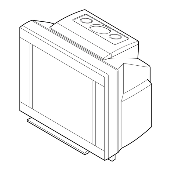
TRINITRON
CHASSIS
COLOR TV
®
Advertisement
Table of Contents

Related Manuals for Sony TRINITRON KV-EX29M63


Summary of Contents for Sony TRINITRON KV-EX29M63
-
Page 1: Service Manual
SERVICE MANUAL AG-3E CHASSIS MODEL COMMANDER DEST. CHASSIS NO. MODEL COMMANDER DEST. CHASSIS NO. KV-EX29M63 RM-964 Thailand SCC-U46A-A KV-EX34M39 RM-963 SCC-U41C-A KV-EX34M69 RM-963 Malaysia SCC-U42C-A KV-EX34M87 RM-963 SCC-U43B-A DRC-MF DRC-MF JUMP JUMP SOUND MODE SURROUND FAVORITE PIC MODE MENU PIP PROGR... - Page 2 CARBON PAINTED ON THE CRT, AFTER REMOVING THE PARTS LIST ARE CRITICAL TO SAFE OPERATION. REPLACE ANODE. THESE COMPONENTS WITH SONY PARTS WHOSE PART NUMBERS APPEAR AS SHOWN IN THIS MANUAL OR IN SUPPLEMENTS PUBLISHED BY SONY. – 2 –...
-
Page 3: Table Of Contents
KV-EX29M63 RM-964 KV-EX34M39/EX34M69/EX34M87 RM-963 TABLE OF CONTENTS Section Title Page Section Title Page SELF DIAGNOSIS FUNCTION 8. DIAGRAMS ........ 4 8-1. Block Diagram ............77 1. GENERAL ................ 7 8-2. Schematic Diagrams ..........84 (1) Schematic Diagrams of F1, J and VM Boards ... 85 2. -
Page 4: Self Diagnosis Function
KV-EX29M63 RM-964 KV-EX34M39/EX34M69/EX34M87 RM-963 SELF DIAGNOSTIC FUNCTION The units in this manual contain a self-diagnostic function. If an error occurs, the STANDBY/TIMER lamp will automatically begin to flash. The number of times the lamp flashes translates to a probable source of the problem. A definition of the STANDBY/TIMER lamp flash indicators is listed in the instruction manual for the user’s knowledge and reference. - Page 5 KV-EX29M63 RM-964 KV-EX34M39/EX34M69/EX34M87 RM-963 2. DISPLAY OF STANDBY/TIMER LIGHT FLASH COUNT Diagnostic Item Flash Count* 2 times +B overcurrent 2 times +B overvoltage 3 times 3 times V deflection stop 4 times White balance failure 5 times Lamp ON 0.3 sec.
- Page 6 KV-EX29M63 RM-964 KV-EX34M39/EX34M69/EX34M87 RM-963 5. HANDLING OF SELF-DIAGNOSTIC SCREEN DISPLAY Since the diagnostic results displayed on the screen are not automatically cleared, always check the self-diagnostic screen during repairs. When you have completed the repairs, clear the result display to “0”.
- Page 7 KV-EX29M63 RM-964 KV-EX34M39/EX34M69/EX34M87 RM-963 – 7 – http://cxema.ru...
- Page 8 KV-EX29M63 RM-964 KV-EX34M39/EX34M69/EX34M87 RM-963 Using Your New TV – 8 – http://cxema.ru...
- Page 9 KV-EX29M63 RM-964 KV-EX34M39/EX34M69/EX34M87 RM-963 Using Your New TV – 9 – http://cxema.ru...
- Page 10 KV-EX29M63 RM-964 KV-EX34M39/EX34M69/EX34M87 RM-963 Using Your New TV – 10 – http://cxema.ru...
- Page 11 KV-EX29M63 RM-964 KV-EX34M39/EX34M69/EX34M87 RM-963 Using Your New TV – 11 – http://cxema.ru...
- Page 12 KV-EX29M63 RM-964 KV-EX34M39/EX34M69/EX34M87 RM-963 Using Your New TV – 12 – http://cxema.ru...
- Page 13 KV-EX29M63 RM-964 KV-EX34M39/EX34M69/EX34M87 RM-963 Using Your New TV – 13 – http://cxema.ru...
- Page 14 KV-EX29M63 RM-964 KV-EX34M39/EX34M69/EX34M87 RM-963 – 14 – http://cxema.ru...
- Page 15 KV-EX29M63 RM-964 KV-EX34M39/EX34M69/EX34M87 RM-963 – 15 – http://cxema.ru...
- Page 16 KV-EX29M63 RM-964 KV-EX34M39/EX34M69/EX34M87 RM-963 – 16 – http://cxema.ru...
- Page 17 KV-EX29M63 RM-964 KV-EX34M39/EX34M69/EX34M87 RM-963 – 17 – http://cxema.ru...
- Page 18 KV-EX29M63 RM-964 KV-EX34M39/EX34M69/EX34M87 RM-963 – 18 – http://cxema.ru...
- Page 19 KV-EX29M63 RM-964 KV-EX34M39/EX34M69/EX34M87 RM-963 – 19 – http://cxema.ru...
- Page 20 KV-EX29M63 RM-964 KV-EX34M39/EX34M69/EX34M87 RM-963 – 20 – http://cxema.ru...
- Page 21 KV-EX29M63 RM-964 KV-EX34M39/EX34M69/EX34M87 RM-963 – 21 – http://cxema.ru...
- Page 22 KV-EX29M63 RM-964 KV-EX34M39/EX34M69/EX34M87 RM-963 – 22 – http://cxema.ru...
- Page 23 KV-EX29M63 RM-964 KV-EX34M39/EX34M69/EX34M87 RM-963 – 23 – http://cxema.ru...
- Page 24 KV-EX29M63 RM-964 KV-EX34M39/EX34M69/EX34M87 RM-963 – 24 – http://cxema.ru...
- Page 25 KV-EX29M63 RM-964 KV-EX34M39/EX34M69/EX34M87 RM-963 – 25 – http://cxema.ru...
- Page 26 KV-EX29M63 RM-964 KV-EX34M39/EX34M69/EX34M87 RM-963 – 26 – http://cxema.ru...
- Page 27 KV-EX29M63 RM-964 KV-EX34M39/EX34M69/EX34M87 RM-963 – 27 – http://cxema.ru...
- Page 28 KV-EX29M63 RM-964 KV-EX34M39/EX34M69/EX34M87 RM-963 – 28 – http://cxema.ru...
- Page 29 KV-EX29M63 RM-964 KV-EX34M39/EX34M69/EX34M87 RM-963 – 29 – http://cxema.ru...
- Page 30 KV-EX29M63 RM-964 KV-EX34M39/EX34M69/EX34M87 RM-963 – 30 – http://cxema.ru...
- Page 31 KV-EX29M63 RM-964 KV-EX34M39/EX34M69/EX34M87 RM-963 – 31 – http://cxema.ru...
- Page 32 KV-EX29M63 RM-964 KV-EX34M39/EX34M69/EX34M87 RM-963 – 32 – http://cxema.ru...
- Page 33 KV-EX29M63 RM-964 KV-EX34M39/EX34M69/EX34M87 RM-963 Using Your New TV – 33 – http://cxema.ru...
- Page 34 KV-EX29M63 RM-964 KV-EX34M39/EX34M69/EX34M87 RM-963 Using Your New TV – 34 – http://cxema.ru...
- Page 35 KV-EX29M63 RM-964 KV-EX34M39/EX34M69/EX34M87 RM-963 Using Your New TV – 35 – http://cxema.ru...
- Page 36 KV-EX29M63 RM-964 KV-EX34M39/EX34M69/EX34M87 RM-963 Using Your New TV – 36 – http://cxema.ru...
- Page 37 KV-EX29M63 RM-964 KV-EX34M39/EX34M69/EX34M87 RM-963 Using Your New TV – 37 – http://cxema.ru...
- Page 38 KV-EX29M63 RM-964 KV-EX34M39/EX34M69/EX34M87 RM-963 – 38 – http://cxema.ru...
- Page 39 KV-EX29M63 RM-964 KV-EX34M39/EX34M69/EX34M87 RM-963 – 39 – http://cxema.ru...
- Page 40 KV-EX29M63 RM-964 KV-EX34M39/EX34M69/EX34M87 RM-963 – 40 – http://cxema.ru...
- Page 41 KV-EX29M63 RM-964 KV-EX34M39/EX34M69/EX34M87 RM-963 – 41 – http://cxema.ru...
- Page 42 KV-EX29M63 RM-964 KV-EX34M39/EX34M69/EX34M87 RM-963 – 42 – http://cxema.ru...
- Page 43 KV-EX29M63 RM-964 KV-EX34M39/EX34M69/EX34M87 RM-963 – 43 – http://cxema.ru...
- Page 44 KV-EX29M63 RM-964 KV-EX34M39/EX34M69/EX34M87 RM-963 – 44 – http://cxema.ru...
- Page 45 KV-EX29M63 RM-964 KV-EX34M39/EX34M69/EX34M87 RM-963 – 45 – http://cxema.ru...
- Page 46 KV-EX29M63 RM-964 KV-EX34M39/EX34M69/EX34M87 RM-963 – 46 – http://cxema.ru...
- Page 47 KV-EX29M63 RM-964 KV-EX34M39/EX34M69/EX34M87 RM-963 – 47 – http://cxema.ru...
- Page 48 KV-EX29M63 RM-964 KV-EX34M39/EX34M69/EX34M87 RM-963 – 48 – http://cxema.ru...
- Page 49 KV-EX29M63 RM-964 KV-EX34M39/EX34M69/EX34M87 RM-963 – 49 – http://cxema.ru...
- Page 50 KV-EX29M63 RM-964 KV-EX34M39/EX34M69/EX34M87 RM-963 – 50 – http://cxema.ru...
- Page 51 KV-EX29M63 RM-964 KV-EX34M39/EX34M69/EX34M87 RM-963 – 51 – http://cxema.ru...
- Page 52 KV-EX29M63 RM-964 KV-EX34M39/EX34M69/EX34M87 RM-963 – 52 – http://cxema.ru...
- Page 53 KV-EX29M63 RM-964 KV-EX34M39/EX34M69/EX34M87 RM-963 – 53 – http://cxema.ru...
-
Page 54: Service Jig
For A to P board extension TOOL (40P), SERVICE 3-702-764-01 For B3 to A board extension TOOL (30P), SERVICE 3-702-773-01 For D to D1 board extension SECTION 4 CIRCUIT BOARDS LOCATION P (EXCEPT KV-EX29M63) V2 (KV-EX34M39/EX34M69) – 54 – http://cxema.ru... -
Page 55: Advance Operation
KV-EX29M63 RM-964 SECTION 5 KV-EX34M39/EX34M69/EX34M87 ADVANCE OPERATION RM-963 5-1. "RESET" FUNCTION 1. Purpose If a customer faces some setting problem that cannot be solved, using the "RESET" function some items will be reset to its original setting (shipping condition) 2. How to Operate There are 2 ways to access to the "RESET"... -
Page 56: Set-Up Adjustments
KV-EX29M63 RM-964 SECTION 6 KV-EX34M39/EX34M69/EX34M87 SET-UP ADJUSTMENTS RM-963 • The following adjustments should be made when a complete Perform the adjustments in the following order : realignment is required or a new picture tube is installed. 1. Beam Landing •... -
Page 57: Convergence Adjustment
KV-EX29M63 RM-964 KV-EX34M39/EX34M69/EX34M87 RM-963 V. STAT 6-2. CONVERGENCE ADJUSTMENT Preparation : • Before starting this adjustment, adjust the focus, horizontal size and vertical size. • Set the PICTURE 70% and BRIGHTNESS 0%. • Cross hatch / Dot pattern. (1) Horizontal and Vertical Static Convergence H. - Page 58 KV-EX29M63 RM-964 KV-EX34M39/EX34M69/EX34M87 RM-963 (2) Dynamic Convergence Adjustment BMC (Hexapole) Magnet. Preparation: If the red, green and blue dots are not balanced or aligned, • Before starting this adjustment, adjust the horizontal static then use the BMC magnet to adjust in the manner described convergence and the vertical static convergence below.
-
Page 59: Focus Adjustment
KV-EX29M63 RM-964 KV-EX34M39/EX34M69/EX34M87 RM-963 (3) Screen-corner Convergence 6-3. FOCUS ADJUSTMENT Note Focus adjustment should be completed before W/B adjustment. (1) Receive digital monoscope pattern. (2) Set "A/V CONTROL" to "STANDARD". a-d : screen-corner (3) Adjust FOCUS VR so that the center of the screen becomes misconvergence just focus. -
Page 60: G2 (Screen) And White Balance Adjustments
KV-EX29M63 RM-964 KV-EX34M39/EX34M69/EX34M87 RM-963 6-5. G2 (SCREEN) AND WHITE BALANCE ADJUSTMENTS 1. G2 (SCREEN) ADJUSTMENT 1) Set the PICTURE and BRIGHTNESS to normal. 2) Put to VIDEO input mode without signals. 3) Connect R, G and B of the C board cathode to the oscilloscope. -
Page 61: Circuit Adjustments
KV-EX29M63 RM-964 SECTION 7 KV-EX34M39/EX34M69/EX34M87 CIRCUIT ADJUSTMENTS RM-963 7-1. ADJUSTMENTS WITH COMMANDER 7-2. ADJUSTMENT METHOD Service adjustments to this model can be performed using the Item Number 00 of device GEO supplied Remote Commander RM-963 and RM-964. This explanation uses V-size as an example. - Page 62 KV-EX29M63 RM-964 KV-EX34M39/EX34M69/EX34M87 RM-963 – 62 – http://cxema.ru...
- Page 63 KV-EX29M63 RM-964 KV-EX34M39/EX34M69/EX34M87 RM-963 – 63 – http://cxema.ru...
- Page 64 KV-EX29M63 RM-964 KV-EX34M39/EX34M69/EX34M87 RM-963 – 64 – http://cxema.ru...
- Page 65 KV-EX29M63 RM-964 KV-EX34M39/EX34M69/EX34M87 RM-963 – 65 – http://cxema.ru...
- Page 66 KV-EX29M63 RM-964 KV-EX34M39/EX34M69/EX34M87 RM-963 – 66 – http://cxema.ru...
- Page 67 KV-EX29M63 RM-964 KV-EX34M39/EX34M69/EX34M87 RM-963 – 67 – http://cxema.ru...
- Page 68 KV-EX29M63 RM-964 KV-EX34M39/EX34M69/EX34M87 RM-963 – 68 – http://cxema.ru...
- Page 69 KV-EX29M63 RM-964 KV-EX34M39/EX34M69/EX34M87 RM-963 – 69 – http://cxema.ru...
- Page 70 KV-EX29M63 RM-964 KV-EX34M39/EX34M69/EX34M87 RM-963 – 70 – http://cxema.ru...
- Page 71 KV-EX29M63 RM-964 KV-EX34M39/EX34M69/EX34M87 RM-963 – 71 – http://cxema.ru...
- Page 72 KV-EX29M63 RM-964 KV-EX34M39/EX34M69/EX34M87 RM-963 – 72 – http://cxema.ru...
- Page 73 KV-EX29M63 RM-964 KV-EX34M39/EX34M69/EX34M87 RM-963 Abbreviation = V-Compressed Mode = Non-compressed Mode ECO = Eco Mode Sur = Surround = Noise Reduction NOTE • shaded items are fixed data. • no data. • Standard data listed on the Adjustment Item Table are reference values, therefore it may be different for each model and for each mode.
-
Page 74: Picture Quality Adjustments
KV-EX29M63 RM-964 KV-EX34M39/EX34M69/EX34M87 RM-963 7-3. PICTURE QUALITY ADJUSTMENTS (ii) Copy SCT data to NTSC (RF MODE) PICTURE ADJUSTMENT 1. Set to service mode. 2. Set A/V control to HI-FINE. 3. Set the following condition. Adjustment condition DYC 00 VR1 - VR2 = VR = 2.35 ± 0.07 (Vp-p) -
Page 75: Deflection Adjustment
KV-EX29M63 RM-964 KV-EX34M39/EX34M69/EX34M87 RM-963 Adjust the following items. 7-4. DEFLECTION ADJUSTMENTS Service Item FOR DRC 1250 (50Hz) MODE Set to Service Mode. GEO : 02 V LINEARITY Input a Pal cross hatch/dot signal. S CORRECTION Set the following condition. H POSITION Picture Mode to [DYNAMIC], Picture Rotation to [+/–0] and... -
Page 76: Picture Distortion Adjustment
KV-EX29M63 RM-964 KV-EX34M39/EX34M69/EX34M87 RM-963 7-6. PICTURE DISTORTION ADJUSTMENT (1) PICTURE DISTORTION ADJUSTMENT (2) Item Number 00 – 0B H-TRAPEZOID (DAC 4 HTR) GEO 0 VSZ (V SIZE) GEO 1 VPS (V POSITION) GEO 2 VLN (V LINEARITY) GEO 3 SCO (VERTICAL S-Correction) - Page 77 http://cxema.ru...
- Page 78 http://cxema.ru...
- Page 79 http://cxema.ru...
- Page 80 http://cxema.ru...
- Page 81 http://cxema.ru...
- Page 82 http://cxema.ru...
- Page 83 http://cxema.ru...
- Page 84 http://cxema.ru...
- Page 85 http://cxema.ru...
- Page 86 http://cxema.ru...
- Page 87 http://cxema.ru...
- Page 88 http://cxema.ru...
- Page 89 http://cxema.ru...
- Page 90 http://cxema.ru...
- Page 91 http://cxema.ru...
- Page 92 http://cxema.ru...
- Page 93 http://cxema.ru...
- Page 94 http://cxema.ru...
- Page 95 http://cxema.ru...
- Page 96 http://cxema.ru...
- Page 97 http://cxema.ru...
- Page 98 http://cxema.ru...
- Page 99 http://cxema.ru...
- Page 100 http://cxema.ru...
- Page 101 http://cxema.ru...
- Page 102 http://cxema.ru...
- Page 103 http://cxema.ru...
- Page 104 http://cxema.ru...
- Page 105 http://cxema.ru...
- Page 106 http://cxema.ru...
- Page 107 KV-EX29M63 RM-964 KV-EX34M39/EX34M69/EX34M87 RM-963 A Board ✼ Mark List KV-EX29M63 KV-EX34M39 KV-EX34M69 KV-EX34M87 C018 100.0 100.0 100.0 C3330 0.1 16V :CHIP 0.1 16V :CHIP 0.1 16V :CHIP C3331 100 16V 100 16V 100 16V C3336 100 16V 100 16V 100 16V...
- Page 108 KV-EX29M63 RM-964 KV-EX34M39/EX34M69/EX34M87 RM-963 DH Board ✼ Mark List KV-EX29M63 KV-EX34M93 KV-EX34M69 KV-EX34M87 C3801 C3804 0.01 C3805 C3807 0.01 C3816 C3819 C3822 0.1 :PP CN3802 CN3804 D3805 ISS119-25 IC3805 LA6510 IC3807 SENSOR UNIT JW3802 10.0MM JW3803 12.5MM JW3804 15.0MM JW3805 5.0MM...
- Page 109 KV-EX29M63 RM-964 KV-EX34M39/EX34M69/EX34M87 RM-963 D1Board ✼ Mark List KV-EX29M63 KV-EX34M39 KV-EX34M69 KV-EX34M87 C4807 0.001 :CHIP 0.0033 :CHIP 0.0033 :CHIP 0.0033 :CHIP C4814 47 25V 47 16V 47 16V 47 16V C4816 0.047 C4817 47 25V 47 16V 47 16V 47 16V...
-
Page 110: Voltage Measurements
KV-EX29M63 RM-964 KV-EX34M39/EX34M69/EX34M87 RM-963 8-3. VOLTAGE MEASUREMENTS A (1/4) BOARD VOLTAGE LIST Pin No. Voltage[v] Pin No. Voltage[v] Pin No. Voltage[v] IC001 IC002 0<[(4.5)]> 3.2[0] 4.5[3.3] IC003 IC1203 ✽ <2.2> 0<(4.5)> 4.5(0) 0.6<1.6> 0.5<1.6> IC1204 IC004 27.5 4.9(0) 0.5<1.6> 0.6[3.5] 13.6... - Page 111 KV-EX29M63 RM-964 KV-EX34M39/EX34M69/EX34M87 RM-963 A (2/4) BOARD VOLTAGE LIST Pin No. Voltage[v] Pin No. Voltage[v] Pin No. Voltage[v] IC1207 0<(9.1)> 0<(4.2)> 0<(6.3)> 6.5<(0)> 0<(5.0)> IC2200 4.2[0] 0<4.5> IC2300 0<(4.5)> 0<(4.3)> 3.6<0> 0<4.9> 0<(6.6)> 0<(9.1)> IC2600 13.0 0<(4.4)> IC2601 IC2603 IC2604 0<(3.8)>...
- Page 112 KV-EX29M63 RM-964 KV-EX34M39/EX34M69/EX34M87 RM-963 A (3/4) BOARD VOLTAGE LIST Pin No. Voltage[v] Pin No. Voltage[v] Pin No. Voltage[v] IC8305 13.1 Q1204 IC8306 0(2.2) Q1205 0<5.5> 0.1<(1.9)> 0<9.0> 0<(1.6)> 0<(4.9)> 5.85 Q1206 5.5[(0)] 2.3[0] Q1207 28.0 18.1 Q1208 13.2 Q1209 13.2 Q1210 13.4[0]...
- Page 113 KV-EX29M63 RM-964 KV-EX34M39/EX34M69/EX34M87 RM-963 A (4/4) BOARD VOLTAGE LIST Pin No. Voltage[v] Pin No. Voltage[v] Pin No. Voltage[v] ✻ Q4307 2.8[0] Q4826 Q8331 ✻ 0[4.5] Q4308 Q8301 Q8332 Q4310 Q8333 Q8302 7.1<6.7> 0<(3.1)> Q4311 Q8303 Q8334 Q4312 Q8304 Q8335 7.1[(6.7)] ✻...
- Page 114 KV-EX29M63 RM-964 KV-EX34M39/EX34M69/EX34M87 RM-963 D1 (1/2) BOARD VOLTAGE LIST Pin No. Voltage[v] Pin No. Voltage[v] Pin No. Voltage[v] IC4800 IC6351 IC6106 IC6107 IC4801 IC6353 11.0 IC6354 IC6108 IC4802 IC6356 -2.8 -6.3 -3.0 IC6101 -3.3 -15.0 -3.5 -3.0 -4.0 -4.1 11.7...
- Page 115 KV-EX29M63 RM-964 KV-EX34M39/EX34M69/EX34M87 RM-963 D1 (2/2) BOARD VOLTAGE LIST Pin No. Voltage[v] Pin No. Voltage[v] Pin No. Voltage[v] Q4809 Q4821 Q6125 Q4810 Q4822 Q6126 Q4811 Q6103 30.2 Q6128 Q4812 Q6104 Q6201 Q4813 Q6105 Q6202 -0.6 Q4814 Q6106 Q6203 -6.0 -3.3 -2.3...
- Page 116 KV-EX29M63 RM-964 KV-EX34M39/EX34M69/EX34M87 RM-963 B3 (1/3) BOARD VOLTAGE LIST Pin No. Voltage[v] Pin No. Voltage[v] Pin No. Voltage[v] IC501 IC504 IC505 IC603 IC506 IC602 IC604 – 146 – http://cxema.ru...
- Page 117 KV-EX29M63 RM-964 KV-EX34M39/EX34M69/EX34M87 RM-963 B3 (2/3) BOARD VOLTAGE LIST Pin No. Voltage[v] Pin No. Voltage[v] Pin No. Voltage[v] IC601 – 147 – http://cxema.ru...
- Page 118 KV-EX29M63 RM-964 KV-EX34M39/EX34M69/EX34M87 RM-963 B3 (3/3) BOARD VOLTAGE LIST Pin No. Voltage[v] Pin No. Voltage[v] Pin No. Voltage[v] Q501 Q521 Q902 Q502 Q522 Q903 Q503 Q523 Q907 Q516 Q601 Q908 Q517 Q602 Q909 Q518 Q901 P BOARD VOLTAGE LIST Pin No.
- Page 119 KV-EX29M63 RM-964 KV-EX34M39/EX34M69/EX34M87 RM-963 VM BOARD VOLTAGE LIST Pin No. Voltage[v] Pin No. Voltage[v] Q5400 Q5405 Q5401 Q5406 Q5402 67.7 Q5407 Q5403 67.8 Q5404 H1 BOARD VOLTAGE LIST Pin No. Voltage[v] IC901 Q1901 Q1902 – 149 – http://cxema.ru...
- Page 120 KV-EX29M63 RM-964 KV-EX34M39/EX34M69/EX34M87 RM-963 V2 BOARD VOLTAGE LIST Pin No. Voltage[V] Pin No. Voltage[V] Pin No. Voltage[V] IC5801 IC5802 Q5801 Q5803 0.02 Q5806 0.03 Q5807 0.04 Q5808 0.04 Q5810 Q5817 0.09 DH BOARD VOLTAGE LIST (KV-EX34 MODEL) Pin No. Voltage[v] Pin No.
- Page 121 KV-EX29M63 RM-964 KV-EX34M39/EX34M69/EX34M87 RM-963 D BOARD VOLTAGE LIST (KV-EX29 MODELS) Pin No. Voltage[v] Pin No. Voltage[v] Pin No. Voltage[v] IC6600 IC6804 11.1 Q6800 -0.5 13.9 IC6805 14.0 Q6803 11.9 ✻ IC6806 Q6804 ✻ 17.8 ✻ 0.01 ✻ 10.4 Q6805 -0.3 Q6100 68.0...
- Page 122 KV-EX29M63 RM-964 KV-EX34M39/EX34M69/EX34M87 RM-963 D BOARD VOLTAGE LIST (KV-EX34 MODEL) Pin No. Voltage[v] Pin No. Voltage[v] Pin No. Voltage[v] IC6600 IC6805 13.7 Q6803 11.9 IC6806 Q6804 Q6805 -0.4 17.5 Q6100 65.5 10.2 Q6806 -0.3 Q6102 54.5 142.8 Q6809 12.4 Q6600 136.2...
-
Page 123: Waveforms
KV-EX29M63 RM-964 KV-EX34M39/EX34M69/EX34M87 RM-963 8-4. WAVEFORMS A BOARD WAVEFORMS 5.5Vp-p 4.2Vp-p 0.4Vp-p 0.4Vp-p 0.3Vp-p 1.5Vp-p 1.6Vp-p 4.4Vp-p 2.8Vp-p 1.4Vp-p NTSC 0.9Vp-p 2.6Vp-p 1.2Vp-p 1.6Vp-p 5.2Vp-p 1.1Vp-p 1.4Vp-p 0.6Vp-p 0.1Vp-p D BOARD WAVEFORMS SECAM/NTSC 0.7Vp-p 30.8Vp-p 0.9Vp-p 1.9Vp-p 53Vp-p 2.9Vp-p 242Vp-p 378Vp-p 76.8Vp-p... - Page 124 KV-EX29M63 RM-964 KV-EX34M39/EX34M69/EX34M87 RM-963 B3 BOARD WAVEFORMS 0.8Vp-p 0.9Vp-p 1.0Vp-p 1.6Vp-p 1.4Vp-p 6.8Vp-p 1.4Vp-p C BOARD WAVEFORMS NTSC SECAM NTSC 120Vp-p 0.6Vp-p 122Vp-p 5.0Vp-p 3.0Vp-p NTSC NTSC NTSC 120Vp-p 114Vp-p 106Vp-p 0.1Vp-p 106Vp-p SECAM/NTSC NTSC 4.0Vp-p 0.3Vp-p 4.1Vp-p 2.2Vp-p 4.0Vp-p...
- Page 125 http://cxema.ru...
- Page 126 http://cxema.ru...
- Page 127 http://cxema.ru...
- Page 128 http://cxema.ru...
- Page 129 http://cxema.ru...
- Page 130 http://cxema.ru...
-
Page 131: Semiconductors
KV-EX29M63 RM-964 KV-EX34M39/EX34M69/EX34M87 RM-963 8-6 SEMICONDUCTORS TRANSISTOR 2SK2663 2SC5480-01 2SA933AS-QT 2SB733-34 2SK2036(TE85L) IRF720-LF49 2SA1776TV2Q 2SD774-34 LETTER SIDE LETTER SIDE DTC144ESA 2SK246-GR 2SC2500-B 2SC3601-E- T.12 2SA2005 DTC144EKA 2SA1175-HFE 2SC2688-LK 2SA1037AK-T146R 2SC5511 2SC2785-HFE 2SA1162-YG 2SC3840(3) 2SC3311A-QRSTA 2SC1623-L5L6 IRF1830G-LF49 2SC2712-YG IRFIB7N50A 2SD601A-Q BA12T... - Page 132 KV-EX29M63 RM-964 KV-EX34M39/EX34M69/EX34M87 RM-963 DIODE CATHODE TOP VIEW Single In -line Package ANODE Pin 8~98 D1NS4 RD12ESB1 MTZJ-7.5B MB88141APF-ER UPC358C BA033FP-E2 ERA82-009 RD30ESB2 MTZJ-T-77-12 CXA1875AM-T4 M24C16-MN6T MTZJ-T-77-10 RD22ESB1 MTZJ-T-77-15 TLC2932IPW TDA9178T/N1.118 MTZJ-T-77-22 ERA85-009 RD18ES-B2 TLC2933IPWR BH3868AFS-E2 MTZJ-T-77-2.2B MTZJ-2.7A RD18ESB MB81F161622B-80FN UPC4558G2 RD5.1ESB2...
-
Page 133: Exploded Views
SPEAKER, (16CM) * 4-046-981-01 BRACKET,SPEAKER 4-302-428-03 SCREW (WASHER HEAD)(+P3 x 12) 4-374-745-21 CUSHION (A) A-1501-737-A 3D BOX ASSY 51-54 X-4038-161-1 REAR COVER ASSY ( 12 SCREWS) (KV-EX29M63) X-4038-310-1 REAR COVER ASSY ( 14 SCREWS) (EXCEPT KV-EX29M63) – 169 – http://cxema.ru... -
Page 134: Chassis
REF. NO. PART NO. DESCRIPTION REMARK REF. NO. PART NO. DESCRIPTION REMARK * A-1372-869-A H1 BOARD, MOUNTED (EXCEPT KV-EX29M63) ! 1-453-326-11 TRANSFORMER ASSY, FLYBACK * A-1372-907-A H1 BOARD, MOUNTED (KV-EX29M63) (NX-4601//J1J4) (KV-EX34M87/KV-EX34M69) * A-1299-376-A A BOARD, COMPLETE (KV-EX29M63) ! 1-453-332-21... -
Page 135: Picture Tube
1-452-896-91 COIL, NA ROTATION (KV-EX29M63) 1-452-896-11 COIL, NA ROTATION (RT200) ! 8-735-056-05 (EXCEPT KV-EX29M63) PICTURE TUBE (M68LNH070X) * A-1342-570-A VM BOARD, MOUNTED (EXCEPT KV-EX29M63) (KV-EX29M63) * A-1342-584-A VM BOARD, MOUNTED (KV-EX29M63) ! 8-735-063-05 PICTURE TUBE (A80LPD10X) (KV-EX34M69) 4-078-765-11 SPRING, EXTENSION (KV-EX29M63) -
Page 136: Electrical Parts List
• MMH : mH, UH : µH noted. number, please include the board name. REF. NO. PART NO. DESCRIPTION REMARK REF. NO. PART NO. DESCRIPTION REMARK * A-1299-376-A A BOARD, COMPLETE (KV-EX29M63) C104 1-126-933-11 ELECT 100UF 20.00%16V ********************* C107 1-163-005-11... - Page 137 5.00% 50V C2617 1-104-665-11 ELECT 100UF 20.00%10V C1268 1-163-017-00 CERAMIC CHIP 0.0047UF 10.00% 50V C3330 1-107-725-11 CERAMIC CHIP 0.1UF 10.00%16V (EXCEPT KV-EX29M63) C1270 1-163-017-00 CERAMIC CHIP 0.0047UF 10.00% 50V C3331 1-126-933-11 ELECT 100UF 20.00%16V C1271 1-136-161-00 FILM 0.047UF 5.00% 50V...
- Page 138 10.00%50V (KV-EX29M63) C8361 1-126-961-11 ELECT 2.2UF 20.00%50V C4366 1-104-760-11 CERAMIC CHIP 0.047UF 10.00% 50V C8366 1-163-021-91 CERAMIC CHIP 0.01UF 10.00%50V (EXCEPT KV-EX29M63) C8367 1-104-664-11 ELECT 47UF 20.00%16V C8368 1-104-664-11 ELECT 47UF 20.00%16V C4367 1-115-185-11 CERAMIC CHIP 0.033UF 10.00% 50V (KV-EX29M63)
- Page 139 1-164-690-91 CERAMIC CHIP 0.0022UF 5.00% 50V D4304 8-719-069-60 UDZS-TE17-9.1B (KV-EX29M63) C8450 1-107-823-11 CERAMIC CHIP 0.47UF 10.00% 16V D4304 8-719-977-22 DTZ9.1 (EXCEPT KV-EX29M63) C8451 1-164-505-11 CERAMIC CHIP 2.2UF D4305 8-719-069-60 UDZS-TE17-9.1B (KV-EX29M63) C8452 1-164-004-11 CERAMIC CHIP 0.1UF 10.00% 25V D4305 8-719-977-22 DTZ9.1 (EXCEPT KV-EX29M63)
- Page 140 L1300 1-414-856-11 INDUCTOR 10UH IC002 8-759-663-29 MM1476AF(TP) L2300 1-414-856-11 INDUCTOR 10UH IC003 8-759-527-77 M24C16-MN6T L3302 1-414-856-11 INDUCTOR 10UH (EXCEPT KV-EX29M63) IC100 8-759-042-02 S-80743AL-A7-S IC1200 8-759-100-96 UPC4558G2 L3303 1-414-856-11 INDUCTOR 10UH (EXCEPT KV-EX29M63) L3304 1-414-856-11 INDUCTOR 10UH (EXCEPT KV-EX29M63) IC1201 8-759-678-92...
- Page 141 Q2305 8-729-230-49 2SC2712-YG R001 1-216-033-00 RES-CHIP 1/10W R002 1-216-033-00 RES-CHIP 1/10W Q2306 8-729-216-22 2SA1162-G R004 1-216-295-11 SHORT Q3300 8-729-026-49 2SA1037AK-T146-R (EXCEPT KV-EX29M63) R005 1-216-295-11 SHORT Q4300 8-729-422-33 2SD601A-Q-TX R006 1-216-029-00 RES-CHIP 1/10W Q4301 8-729-230-49 2SC2712-YG Q4302 8-729-216-22 2SA1162-G R008 1-216-065-91 RES-CHIP 4.7K...
- Page 142 1-216-025-11 RES-CHIP 1/10W R1236 1-216-081-00 RES-CHIP 1/10W R105 1-216-295-11 SHORT R1237 1-216-097-11 RES-CHIP 100K 1/10W R107 1-216-073-00 RES-CHIP 1/10W (EXCEPT KV-EX29M63) R1238 1-216-073-00 RES-CHIP 1/10W R109 1-216-041-00 RES-CHIP 1/10W R1239 1-216-073-00 RES-CHIP 1/10W R1240 1-216-041-00 RES-CHIP 1/10W R110 1-216-043-91 RES-CHIP...
- Page 143 RES-CHIP 1/10W R3362 1-216-025-11 RES-CHIP 1/10W R4367 1-216-025-11 RES-CHIP 1/10W (EXCEPT KV-EX29M63) R4369 1-216-025-11 RES-CHIP 1/10W R3374 1-216-295-11 SHORT 0 (EXCEPT KV-EX29M63) R4370 1-216-049-11 RES-CHIP 1/10W R4300 1-216-025-11 RES-CHIP 1/10W R4372 1-216-049-11 RES-CHIP 1/10W R4301 1-216-025-11 RES-CHIP 1/10W R4373 1-216-295-11...
- Page 144 RES-CHIP 220K 1/10W R8316 1-216-113-00 RES-CHIP 470K 1/10W R4402 1-216-129-00 RES-CHIP 2.2M 1/10W R8321 1-216-025-11 RES-CHIP 1/10W (KV-EX29M63 ONLY) (EXCEPT KV-EX29M63/EX34M87) R4403 1-216-049-11 RES-CHIP 1/10W R8322 1-216-022-00 RES-CHIP 1/10W (KV-EX29M63 ONLY) R8323 1-216-295-11 SHORT R4404 1-208-814-91 METAL CHIP 0.5% 1/10W...
- Page 145 R8465 1-216-025-11 RES-CHIP 1/10W R8466 1-216-025-11 RES-CHIP 1/10W <TUNER> R8467 1-216-041-00 RES-CHIP 1/10W TU101 8-598-451-00 TUNER, FSS BTF-WG441 (KV-EX29M63) R8468 1-216-041-00 RES-CHIP 1/10W TU101 8-598-452-20 TUNER, FSS BTF-WG442 (KV-EX34M39/EX34M69) R8469 1-216-041-00 RES-CHIP 1/10W TU101 8-598-450-10 TUNER, FSS BTF-LG434 (KV-EX34M87) R8470...
- Page 146 * A-1136-150-A B3 BOARD, COMPLETE (KV-EX29M63) C611 1-163-021-91 CERAMIC CHIP 0.01UF 10.00%50V ********************* C612 1-163-021-91 CERAMIC CHIP 0.01UF 10.00%50V * A-1136-132-A B3 BOARD, COMPLETE (EXCEPT KV-EX29M63) ********************* C613 1-163-021-91 CERAMIC CHIP 0.01UF 10.00%50V C614 1-163-021-91 CERAMIC CHIP 0.01UF 10.00%50V C615...
- Page 147 KV-EX29M63 RM-964 KV-EX34M39/EX34M69/EX34M87 The components identified by shading and mark ! are critical for safety. RM-963 Replace only with part number specified. REF. NO. PART NO. DESCRIPTION REMARK REF. NO. PART NO. DESCRIPTION REMARK FL504 1-234-177-21 FILTER, CHIP EMI <RESISTOR>...
- Page 148 KV-EX29M63 RM-964 KV-EX34M39/EX34M69/EX34M87 The components identified by shading and mark ! are critical for safety. RM-963 Replace only with part number specified. REF. NO. PART NO. DESCRIPTION REMARK REF. NO. PART NO. DESCRIPTION REMARK R604 1-216-033-00 RES-CHIP 1/10W R684 1-216-073-00...
- Page 149 Replace only with part number specified. REF. NO. PART NO. DESCRIPTION REMARK REF. NO. PART NO. DESCRIPTION REMARK * A-1332-131-A C BOARD, MOUNTED (KV-EX29M63) <DIODE> ******************** * A-1332-123-A C BOARD, MOUNTED (EXCEPT KV-EX29M63) D9002 8-719-400-75 MA3091 ******************** D9005 8-719-073-01 MA111-(K8).S0 D9006 8-719-051-85...
- Page 150 CERAMIC CHIP 0.01UF 10.00%50V *********************************************************************** C6619 1-161-830-00 CERAMIC 0.0047UF 500V C6620 1-163-021-91 CERAMIC CHIP 0.01UF 10.00%50V * A-1348-013-A D BOARD, COMPLETE (KV-EX29M63) C6621 1-131-940-11 ELECT 1200UF 250V ********************* (KV-EX34M87 ONLY) * A-1348-020-A D BOARD, COMPLETE (KV-EX34M39) ********************* C6622 1-131-940-11 ELECT 1200UF...
- Page 151 REMARK C6649 1-125-969-91 CERAMIC 680PF 10.00% 1KV C6831 1-117-838-11 FILM 8200PF 3.00% 1.5KV C6650 1-125-969-91 CERAMIC 680PF 10.00% 1KV (EXCEPT KV-EX29M63) C6651 1-125-969-91 CERAMIC 680PF 10.00% 1KV C6832 1-117-836-11 FILM 6800PF 3.00% 1.5KV C6652 1-110-626-11 ELECT 330UF 20.00% 160V (KV-EX29M63)
- Page 152 CN6602* !1-508-786-13 PIN, CONNECTOR (5MM PITCH) 2P D6620 8-719-063-73 D1NL20U-TR D6623 8-719-911-19 1SS119-25 (EXCEPT KV-EX29M63) D6631 8-719-050-18 D4SBL20U CN6603* !1-691-134-11 PIN, CONNECTOR (PC BOARD) 2P (KV-EX29M63) D6632 8-719-073-01 MA111-(K8).S0 CN6603* !1-573-963-11 PIN, CONNECTOR (PC BOARD) 3P D6633 8-719-510-12 D10SC4M (EXCEPT KV-EX29M63) D6635 8-719-110-47...
- Page 153 IC6801 8-759-450-95 LM393N Q6602 8-729-119-78 2SC2785-HFE (KV-EX34M87 ONLY) IC6804 8-759-394-36 BA09T IC6805 8-759-394-35 BA12T Q6603 8-729-052-32 IRFIB7N50A IC6806 8-749-013-76 PQ6RD83B (EXCEPT KV-EX29M63) Q6604 8-729-119-76 2SA1175-HFE Q6605 8-729-230-49 2SC2712-YG Q6608 8-729-200-21 2SC2500-B <CHIP CONDUCTOR> Q6609 8-729-029-56 DTA144ESA JR6601 1-216-295-11 SHORT Q6610...
- Page 154 KV-EX29M63 RM-964 KV-EX34M39/EX34M69/EX34M87 The components identified by shading and mark ! are critical for safety. RM-963 Replace only with part number specified. REF. NO. PART NO. DESCRIPTION REMARK REF. NO. PART NO. DESCRIPTION REMARK R6105 1-216-097-11 RES-CHIP 100K 1/10W R6637...
- Page 155 1-208-796-11 METAL CHIP 3.9K 0.5% 1/10W (KV-EX29M63) R6855 1-214-899-81 METAL 1/2W R6804 1-208-795-11 METAL CHIP 3.6K 0.5% 1/10W (KV-EX29M63) (EXCEPT KV-EX29M63) R6855 1-214-898-81 METAL 1/2W R6805 1-208-802-11 METAL CHIP 6.8K 0.5% 1/10W (EXCEPT KV-EX29M63) R6856 1-215-923-00 METAL OXIDE R6806 1-208-796-11 METAL CHIP 3.9K...
- Page 156 1/10W * A-1343-987-A D1 BOARD, MOUNTED (KV-EX29M63) R6889 1-260-125-11 CARBON 150K 1/2W ***************** R6890 1-260-125-11 CARBON 150K 1/2W * A-1343-962-A D1 BOARD, MOUNTED (EXCEPT KV-EX29M63) R6891 1-216-069-00 RES-CHIP 6.8K 1/10W ***************** R6892 1-216-097-11 RES-CHIP 100K 1/10W 4-382-854-11 SCREW (M3X10), P, SW (+)
- Page 157 C6210 1-163-009-11 CERAMIC CHIP 0.001UF 10.00% 50V D6107 8-719-109-84 RD5.1ES-B1 (KV-EX29M63) C6211 1-126-964-11 ELECT 10UF 20.00% 50V D6107 8-719-109-85 RD5.1ESB2 (EXCEPT KV-EX29M63) D6108 8-719-911-19 1SS119-25 C6212 1-164-222-11 CERAMIC CHIP 0.22UF D6109 8-719-911-19 1SS119-25 C6350 1-164-004-11 CERAMIC CHIP 0.1UF 10.00% 25V...
- Page 158 IC6354 8-759-325-48 CA0005AD Q6105 8-729-230-49 2SC2712-YG IC6356 8-759-822-38 LA6510 Q6106 8-729-026-49 2SA1037AK-T146-R Q6107 8-729-140-93 2SB733-34 <CHIP CONDUCTOR> Q6108 8-729-026-49 2SA1037AK-T146-R (EXCEPT KV-EX29M63) Q6118 8-729-230-49 2SC2712-YG JR6100 1-216-295-11 SHORT Q6124 1-801-806-11 TR DTC144EKA JR6101 1-216-295-11 SHORT JR6102 1-216-295-11 SHORT Q6125 8-729-230-49...
- Page 159 1/10W R4821 1-216-073-00 RES-CHIP 1/10W (KV-EX29M63) R4822 1-216-049-11 RES-CHIP 1/10W R4854 1-216-061-00 RES-CHIP 3.3K 1/10W R4823 1-216-049-11 RES-CHIP 1/10W (EXCEPT KV-EX29M63) R4824 1-216-073-00 RES-CHIP 1/10W R4855 1-216-065-91 RES-CHIP 4.7K 1/10W R4825 1-216-073-00 RES-CHIP 1/10W (KV-EX29M63) R4826 1-216-049-11 RES-CHIP 1/10W R4855...
- Page 160 0.5% 1/10W (KV-EX29M63) R6106 1-208-798-11 METAL CHIP 4.7K 0.5% 1/10W R6154 1-208-806-11 METAL CHIP 0.5% 1/10W R6107 1-216-057-00 RES-CHIP 2.2K 1/10W (EXCEPT KV-EX29M63) R6108 1-216-073-00 RES-CHIP 1/10W R6155 1-208-822-11 METAL CHIP 0.5% 1/10W R6109 1-216-073-00 RES-CHIP 1/10W R6156 1-216-077-91 RES-CHIP...
- Page 161 Replace only with part number specified. REF. NO. PART NO. DESCRIPTION REMARK REF. NO. PART NO. DESCRIPTION REMARK R6213 1-216-097-11 RES-CHIP 100K 1/10W * A-1333-012-A DH BOARD, MOUNTED (KV-EX29M63) R6215 1-208-836-11 METAL CHIP 180K 0.5% 1/10W ********************* R6216 1-216-065-91 RES-CHIP 4.7K 1/10W...
- Page 162 DESCRIPTION REMARK REF. NO. PART NO. DESCRIPTION REMARK <RESISTOR> A-1241-446-A F1 BOARD, MOUNTED (KV-EX29M63) ********************* R3802 1-249-417-11 CARBON 1/4W A-1241-448-A F1 BOARD, MOUNTED (EXCEPT KV-EX29M63) (KV-EX34M69 ONLY) ********************* R3803 1-249-417-11 CARBON 1/4W (KV-EX34M69 ONLY) 1-533-223-11 HOLDER, FUSE R3804 1-215-444-00 METAL 9.1K...
- Page 163 REF. NO. PART NO. DESCRIPTION REMARK * A-1372-907-A H1 BOARD, MOUNTED (KV-EX29M63) R1914 1-249-411-11 CARBON 1/4W ********************* R1915 1-249-429-11 CARBON 1/4W * A-1372-869-A H1 BOARD, MOUNTED (EXCEPT KV-EX29M63) R1916 1-249-401-11 CARBON 1/4W ********************* R1917 1-247-807-31 CARBON 1/4W * 4-055-304-01 HOLDER, LED R1920...
- Page 164 ENCAPSULATED COMPONENT *********************************************************************** FL8803 1-236-071-11 ENCAPSULATED COMPONENT FL8804 1-236-071-11 ENCAPSULATED COMPONENT FL8805 1-236-071-11 ENCAPSULATED COMPONENT FL8808 1-236-071-11 ENCAPSULATED COMPONENT * A-1195-161-A P BOARD, COMPLETE (EXCEPT KV-EX29M63) ******************** <IC> IC8801 8-759-658-34 SDA9588X <CAPACITOR> IC8802 8-759-460-72 BA033FP-E2 C8801 1-104-665-11 ELECT 100UF 20.00% 10V...
- Page 165 KV-EX29M63 RM-964 KV-EX34M39/EX34M69/EX34M87 The components identified by shading and mark ! are critical for safety. RM-963 Replace only with part number specified. (EXCEPT KV-EX29M63) (KV-EX34M39/EX34M69) REF. NO. PART NO. DESCRIPTION REMARK REF. NO. PART NO. DESCRIPTION REMARK <RESISTOR> * A-1347-165-A V2 BOARD, COMPLETE (KV-EX34M39/...
- Page 166 REF. NO. PART NO. DESCRIPTION REMARK Q5810 8-729-120-28 2SC1623-L5L6 * A-1342-584-A VM BOARD, MOUNTED (KV-EX29M63) Q5817 8-729-026-49 2SA1037AK-T146-R ********************** * A-1342-570-A VM BOARD, MOUNTED (EXCEPT KV-EX29M63) ********************** <RESISTOR> 4-382-854-11 SCREW (M3X10), P, SW (+) R5800 1-208-806-11 METAL CHIP 0.5% 1/10W R5801 1-216-295-11...
- Page 167 4-065-210-01 JOINT R5420 1-249-421-11 CARBON 2.2K 1/4W * 4-054-764-01 BAG, PROTECTION (KV-EX29M63) R5421 1-249-385-11 CARBON 1/4W * 4-074-148-01 BAG, PROTECTION (EXCEPT KV-EX29M63) R5422 1-249-405-11 CARBON 1/4W 4-059-705-11 CLIP (KV-EX29M63) R5423 1-215-915-11 METAL OXIDE 4-392-004-11 CLIP (EXCEPT KV-EX29M63) R5424 1-249-395-11 CARBON...
- Page 168 Replace only with part number specified. REF. NO. PART NO. DESCRIPTION REMARK REF. NO. PART NO. DESCRIPTION REMARK Sony Corporation English 2000IG70186-1 Sony Technology Malaysia Sdn. Bhd. Printed in Malaysia 9-872-220-01 Visual Entertainment General Area 2000.9 – 204 – http://cxema.ru...
Need help?
Do you have a question about the TRINITRON KV-EX29M63 and is the answer not in the manual?
Questions and answers