Table of Contents
Advertisement
RETAIN THESE INSTRUCTIONS
FOR FUTURE REFERENCE
INSTALLATION
INSTRUCTIONS
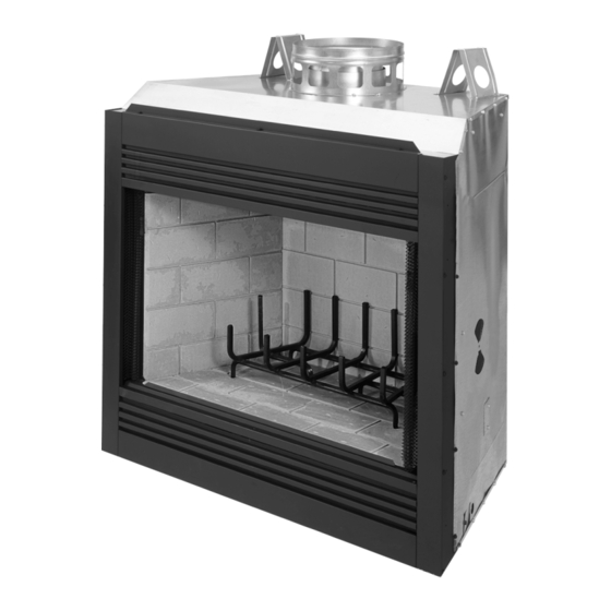
42" Wood Burning Fireplaces
P/N 850,047M REV. N/C 01/2007
MODELS
RD-42
RD-42-H
RDI-42
RDI-42-H
This installation manual will enable you to obtain a safe, efficient and
dependable installation of your fireplace system. Please read and under-
stand these instructions before beginning your installation.
Do not alter or modify the fireplace or its components under any
circumstances. Any modification or alteration of the fireplace system,
including but not limited to the fireplace, chimney components and
accessories, may void the warranty, listings and approvals of this system
and could result in an unsafe and potentially dangerous installation.
IMPORTANT! TO ASSURE PROPER ALIGNMENT OF GLASS DOORS:
INSTALL THIS FIREPLACE IN A SQUARE AND PLUMB CONDITION,
USING SHIMS AS NECESSARY AT SIDES AND/OR BOTTOM.
PLEASE RETAIN THIS MANUAL FOR FUTURE REFERENCE.
NOTE: DIAGRAMS & ILLUSTRATIONS NOT TO SCALE.
®
MERIT
SERIES
HC-42
HC-42-H
HCI-42
HCI-42-H
WH Report No. J9902-5865C-231
1
Advertisement
Table of Contents

Subscribe to Our Youtube Channel
Related Manuals for Lennox RD-42


Summary of Contents for Lennox RD-42
- Page 1 INSTALLATION INSTRUCTIONS ® MERIT SERIES 42" Wood Burning Fireplaces P/N 850,047M REV. N/C 01/2007 MODELS RD-42 HC-42 RD-42-H HC-42-H RDI-42 HCI-42 RDI-42-H HCI-42-H This installation manual will enable you to obtain a safe, efficient and dependable installation of your fireplace system. Please read and under- stand these instructions before beginning your installation.
-
Page 2: Table Of Contents
TABLE OF CONTENTS 2. Always check your local building codes. The The manufacturer is not responsible for any installation must comply with all local, regional, smoking or related problems that may result state and national codes and regulations. from the lack of adequate combustion air. It is Safety Rules ........ -
Page 3: Precautions
PRECAUTIONS Note: Illustrations shown reflect “typical” WARNING: FAILURE TO USE MANUFAC- installations with nominal dimensions and TURE PROVIDED PARTS, VARIATIONS IN Note: These fireplace systems are not difficult are for design and framing reference only. TECHNIQUES AND CONSTRUCTION MA- to install. However, in the interest of safety, it is Actual installations may vary due to indi- TERIALS OR PRACTICES OTHER THAN recommended that the installer be a qualified or... -
Page 4: Assembly Outline
Chimney Height LOCATION OF FIREPLACE Insulate Joists Same As Ceiling The total height of your completed fireplace Carefully select the proper location for heat system from the surface the fireplace rests on circulation, aesthetics, chimney obstructions to the chimney top must not exceed 60' and and clearance to side wall(s). -
Page 5: Assembly Steps
ASSEMBLY STEPS 1. Estimate the total weight of the fireplace Top Spacer system including chimney and surround ma- terials such as brick, stone, etc., to be in- Note: The following steps represent the normal Maintain stalled. Shipping weights for the fireplace 1"... -
Page 6: Fireplace Specifications
FIREPLACE SPECIFICATIONS 12 ¹⁄₂" (318 mm) 8 ³⁄₈" (213 mm) 16 ⁵⁄₁₆" (414 mm) 1 ¹⁄₂" Metal Safety Strips 41" 46 ³⁄₈" (1041 mm) (1178 mm) 22 ⁵⁄₁₆" 2 ⁷⁄₈" Figure 8 (566 mm) (73 mm) 7 ³⁄₄" (197 mm) Blocking 46 ³⁄₄"... -
Page 7: Framing Specifications
FRAMING SPECIFICATIONS Framing Dimensions 48" 1219 mm Back Wall of FOAK Combustion Chase/Enclosure Air Kit - Optional 46 ¹⁄₂" 1181 mm Including Finising Materials if any 33" 838 mm 17 ¹⁄₂" 445 mm 81" 2057 mm Header 40 ³⁄₈" 1026 mm 24"... -
Page 8: Installing The Chimney System
Step 4. Fireplace should be secured to side Note: If the fireplace is installed against an framing members using the full length nailing inside wall, the Class 0 metallic air duct may be extended into a ventilated attic space at least 18" tabs at the top and bottom of the fireplace front face. -
Page 9: Offset Through Floor/Ceiling
CHIMNEY 30° OFFSET THROUGH FLOOR Step 4. Note: Chimney sections are con- Note: Assemble one component of chimney at structed with a unique locking tab design, a time (inner section first, then outer section OR CEILING last) before proceeding with the next complete which ensures an immediate, tight assembly between sections. - Page 10 Note: Do not apply excessive pressure to any Step 8. The standard Security Chimneys FTF8 Step 10. Using a FTF8-CTD Round Termination: subsequent chimney sections following the roof flashing assemblies include a storm collar. stabilizer when installing. Ensure each subse- Slide the storm collar over outer chimney, rest 1.
-
Page 11: Ten Foot Rule Summary
To determine the number of chimney sections Less Than 10' and chimney components required, follow these steps: 2' Min. 1. Determine total vertical height of the fireplace installation. This dimension is the distance from the surface the fireplace sets on to the point where smoke exits from the termination. -
Page 12: Vertical Elevation Chart
FTF8 VERTICAL ELEVATION CHART The offset and return elbows may be attached together, or a section or sections of chimney may be used between, but do not exceed 20' in Height Of Number Of FTF8 Height Of Number Of FTF8 total length between elbows. -
Page 13: Offset Elevation Chart
OFFSET ELEVATION CHART FTF8-ES30 Number of FTF8 Chimney Sections Return Offset Height Offset/Return FTF8-S4 Elbow (Inches) (Inches) Elbow Stabilizer 12" 18" 36" 48" Max. 15 ³⁄₄ 24 ¹⁄₂ 29 ³⁄₄ Stabilizer 14 ¹⁄₄ 33 ¹⁄₂ 17 ¹⁄₄ 38 ¹⁄₂ 20 ¹⁄₄ 43 ³⁄₄... -
Page 14: Installing Offsets
INSTALLING OFFSETS Step 5. Secure support straps to framing members by nailing under tension in sheer ( Figure 41 ). First, review the Offset Elevation Chart and Joints Figure 38 for reference. Step 1. Determine the offset distance where Chimney Section chimney is to pass through the first ceiling- dimension “A.”... -
Page 15: Combustion Air Kits
After completing the installation of the optional Note: Using a soapy water solution (50% dish POWER TO THE FIREPLACE The Optional Blower Kit combustion air vent system the actuator arm soap, 50% water) is an effective leak test Operates on 115 volt 60 Hz 150 watts AC solution but it is not recommended, because must be put in service and tested to ensure... -
Page 16: Glass Doors
If you’re installing a gas line, connect it before It is especially important to insulate between Finished Wall Header the fireplace is framed and enclosed in the the studs of an outside chase cavity and under 12" finished wall. The gas knockout is determined the floor if the floor is above ground level. - Page 17 Hearth Extension Dimensions 16" 38" 8" 54" Note: To convert inches to millimeters divide by 0.03937 Figure 47 Methods of Determini Answer - The minimum required thickness of the Micore 160 is .875”, ng Hearth Extension and Wall Shield therefore round up to 7/8” and use the nearest standard thickness available Equivalents - To determine the thickness required for the alternate which is 1”.
-
Page 18: Finish Requirements
The sum of all “R values” is: .70 + .10 +. 038 + .10 = .938 12" Min. This would NOT be an acceptable combination of material for the hearth extension since the total calculated “R value” of the materials used 5 1/2"... -
Page 19: Installation Components
INSTALLATION COMPONENTS The following items are available for use in the (FBK-200 Models Only) installation of this appliance. Chimney Section 63L10 FTF8-12 63L13 FTF8-18 63L14 FTF8-36 Forced Air Blower Kits 63L15 FTF8-48 -Single Speed 80L84 FBK-100 Canadian 62L92 FTF8-18C -Variable Speed 80L85 FBK-200 Firestop Spacer (30°) - Page 20 The manufacturer reserves the right to make changes at any time, without notice, in design, materials, specifications, prices and also to discontinue colors, styles and products. Consult your local distributor for fireplace code information. Printed in U.S.A. © 2007 by LENNOX HEARTH PRODUCTS 1110 West Taft Avenue P/N 850,047M REV.
Need help?
Do you have a question about the RD-42 and is the answer not in the manual?
Questions and answers