Table of Contents
Advertisement
Advertisement
Table of Contents

Related Manuals for Sky Control SC8100

Summary of Contents for Sky Control SC8100
- Page 1 Configuration Manual SC8100 SC8110...
-
Page 3: Table Of Contents
1-Wire reader connection I-Touch Button connection Cleaning, battery disposal and replace- Proximity reader connection ment Relay outputs connection Disposal Connection of loads to SC8100 Battery replacement Connection of loads to SC8110 Cleaning of appliance Backup battery connection USB camera connection Warranty... -
Page 4: Introduction
Product description Analog sensors Sky Control appliances - monitoring units Temperature sensor SC8100 and SC8110 - are the main Sky Control (SC500) modules for monitoring and environmental control. These main modules have 8 analog ports for connecting Sky Control analog sensors,... - Page 5 Introduction Analog sensors CAN sensors PIR, vibration, tem- perature CAN sensor PIR sensor (SC570) (SC470) Smoke, humidity and Leak sensor (SC590) temperature CAN sen- sor (SC460) Cable leak sensor (SC591) Modules Dry contacts unit (SC16) Current loop converter 4-20 mA (SC420) GSM modem (SC920) CAN modules Airflow and tempera-...
-
Page 6: Physical Description
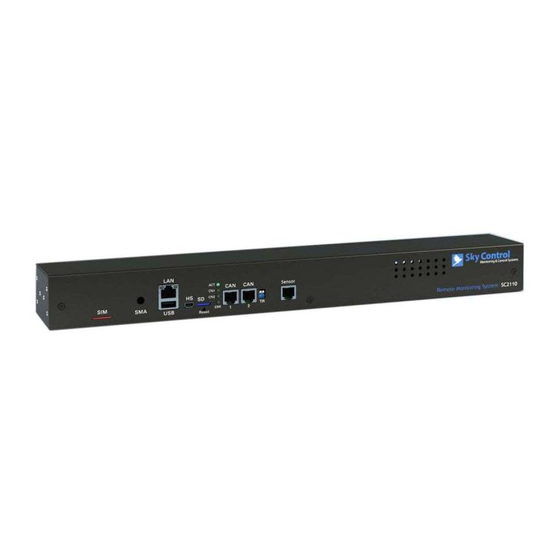
Physical Description Physical Description Front panel SC81xx “LAN” - Ethernet 10/100 Base-T port, “CAN” - two equivalent digital connectors provides Ethernet connection. LEDs - “yel- RJ12 for the connection of CAN sensors low” (status) and “green” (traffic) shows and CAN extensions on a CAN bus, with the network traffic. -
Page 7: Back Panel
Physical Description Back panel SC8100 Back panel SC8110 “AC line” - power input 240V. IEC C14 con- “DC 12V” - backup power socket, to con- nector. nect a battery or a battery backup. “Fuse” - 0.2A type 5*20 “Dry contacts” - empty slot for dry contacts module SC16, used to connect dry con- “Output 1..4”... -
Page 8: Inventory Inventory
IEC-320-C13 power cord damage occurred during transportation, contact the appropriate delivery service. Description 1.8-m NEMA 5-15P to IEC-320-C13 power cord Monitoring unit SC8100. only SC8110 RJ45 1m patch cable 19” rack brackets - 2 pcs. USB-miniUSB cable M3 x 8 Phillips flat-head screws - 6 pcs. - Page 9 Inventory Description Relay terminal plug 5.08 mm - 1 pc only SC8100 Relay terminal plug 5.08 mm - 1 pcs only SC8100 CD-ROM with documen- tation and software Configuration manual Warranty card...
-
Page 10: Installation
Installation Installation Installation of appliance nect approved devices to ports on the unit as di- rected in this manual. Plugging in other devices The unit can be installed in the front or rear of may result in equipment damage. the rack, or can be put on the shelf using self- adhesive rubber feet. -
Page 11: Appliance Connections
Installation Connect the appropriate power cord to the Plug the power cable into the power unit AC line input. source. Connect unit’s LAN port using network cable to the switch. Appliance connections Analog sensors connection Icon Analog sensors Temperature sensor (SC500) Outdoor temperature sensor (SC501) Humidity sensor (SC510) -
Page 12: Can Sensors Connection
CN2 on the appliance using an FTP CAN RJ- Sensors are shown on p. 2-3. 12(6P6C) cable supplied. CAN sensors can also be connected to the port of another Sky Control Connect analog sensor by a supplied RJ-11 CAN sensor or CAN device connected to appli- (6P4C) cable to any analog port A1 .. -
Page 13: I-Touch Button Connection
Installation of the device type and connection will occur I-Touch or 1-Wire Proximity readers can be con- automatically. nected using RJ9 (4P4C) connector via input “1- Wire” of an appliance. The reader is determined automatically. 1-Wire reader connection I-Touch Button connection Readers I-BUTTON have two wires. -
Page 14: Relay Outputs Connection
Each appliance has the possibility to connect up sible output current of the relay - 5A. to 4 loads managed by built-in relays . In the case of SC8100 built-in relays have independent separate entrances and exits. In case of SC8110... -
Page 15: Connection Of Loads To Sc8110
Installation Do not insert the terminal plug into the internal voltage 12V. relay terminal socket RLY1 ... RLY4 when external voltage source is turned on. USB camera connection Connection of loads to SC8110 To connect an external load, сonnect NEMA power cable from the load to the output “Output 1 .. -
Page 16: Gsm Modem Connection
Installation Inventory Dry contacts board BH10 cable If necessary, connect dry contacts to the module with appropriate 3.5 mm terminals from supply. Relay terminal plugs Screw M3*5 GSM modem connection Inventory Set up dry contacts module on 3 steel spacing sleeves inside the appliance case, attach the board with three M3 screws from supply to the sleeves. - Page 17 Installation Inventory Set the SMA connector antenna cable to the rear or to the front panel of the appli- ance into the corresponding SMA hole. Put on the SMA connector gold-plated washer and nut from the supply, holding SMA con- nector with one key, securely tighten the nut with the other key.
-
Page 18: Initial Configuration
Initial Configuration Initial Configuration Overview To start working with the appliance your PC must have subnet and subnet mask You must configure the following TCP/IP settings compatible with new appliance! Use your PC before the appliance can operate in a network: with any permitted IP-address: 192.168.0.XXX, where XXX = number from 0 to 192, and sub- IP-address of device... -
Page 19: Access
Initial Configuration IP-address will be in the first lines of this file. remove this ID. In this case, third-party users can not log into the system. To add a new user, administrator needs to enter a new ID, and it is necessary to mark read and write privileges. -
Page 20: Quick Configuration
Initial Configuration Quick Configuration In such case you may get the following mes- sage: Turn on the appliance, set up the network set- tings, proceed to configure other settings and Logic scheme name actions. if ‘S/N iButton’(id=13) in state ‘alarm’, Alert actions then ‘Email’(id=302) changes to state ‘on’... -
Page 21: Timer
Initial Configuration IP cameras Timer To add an IP camera, go to the folder “Add” in the upper left corner of the web interface, select item “Add IP camera” and click. Fill in empty fields, give name to created camera and save. Groups To add a timer, go to the folder “Add”... -
Page 22: Access Control
Initial Configuration To add, edit, deactivate or remove a logic the settings for the required sensor and click scheme, go to the folder “Preferences” in the “Set and Close” item. appliance web interface , select the folder “Logic Setting thresholds is not always convenient schemes”... -
Page 23: Upgrade Options
Upgrade options Upgrade options Software Upgrades Upgrade via USB To upgrade via USB, copy the update file The appliance has the possibility to update or to (“sky25firmware.sky”), the system settings file restore software. You can update software via (“sky25settings.sky”) or/and reset the pass- HTTP, FTP or using USB flash drive. - Page 24 Upgrade options to “ON”. If the appliance has GSM modem, con- nect modem cable back to modem connector J5. Close the cover, turn the power on, and test the system. motherboard. If the appliance has a GSM mo- dem, it must be turned off, disconnect modem cable from modem connector J5.
-
Page 25: Cleaning, Battery Disposal And Replace
Cleaning and warranty Cleaning, battery disposal and replacement Disposal Cleaning Sky Control appliance contains replaceable silver Use a soft dry cloth to clean the appliance. oxide coin-cell battery SR44. Silver oxide batter- ies contain a small amount of mercury and can Warranty be recycled to recover it. -
Page 26: Technical Parameters
Technical parameters Electrical characteristics Value Input voltage, nominal 100—240 VAC; 50/60 Hz The maximum power consumption 30 W The maximum switching power for SC8100 4*5A/240V The maximum switching power for SC8110 10A/240V No more then 5A on output! Physical characteristics Value... - Page 28 www.skycontrol.com...
Need help?
Do you have a question about the SC8100 and is the answer not in the manual?
Questions and answers