Table of Contents
Advertisement
Advertisement
Table of Contents

Related Manuals for Sky Control SC8100

Summary of Contents for Sky Control SC8100
- Page 1 Configuration manual Monitoring systems SC8100, SC8110, SC2100, SC2110...
-
Page 3: Table Of Contents
Creating groups of elements Connecting 1-Wire reader Creating notifications Connecting I-Touch Button Notification via E-mail Connecting Proximity reader Notification via SNMP Trap Connecting relays Notification via SMS Connecting the load to SC8100 Macros in the notification text Connecting the load to SC8110... - Page 4 Creating ping Creating timer Adding IP camera Adding logic schemes Example of adding a logic scheme Access control Adding a key Managing keys Setting up GSM modem Configuring GSM modem SMS notifications SMS commands Sending SMS from PC Setting up CAN Setting up dynamic DNS Upgrade and restore options Description...
-
Page 5: Introduction
Related documents Sky Control appliances - monitoring units Unless otherwise noted, the following documen- SC8100, SC8110, SC2100 and SC2110 - are tation is available on the CD provided with the the main Sky Control modules for monitor- device or on the web page: ing and environmental control. - Page 6 Introduction Analog sensors Analog sensors Leak sensor (SC590) Humidity sensor (SC510) Cable leak sensor AC voltage monitor (SC591) (SC520) Access sensor (SC530) CAN modules Airflow and tempera- ture unit (SC450) Vibration sensor (SC540) Vibration sensor Analogue sensor mod- (SC541). Chain con- ule (SC408) nection possible.
- Page 7 Introduction CAN sensors PIR, vibration, tem- perature CAN sensor (SC470) Smoke, humidity and temperature CAN sen- sor (SC460) Embedded modules Dry contacts unit (SC16) GSM modem (SC920)
-
Page 8: Comparison Charts & Specifications
Charts and specifications Comparison charts & specifications Master modules SC2100, SC2110, SC8100, SC8110 and SC1108 are master modules and cannot connect to each other. For scalability please use extension modules and embedded modules. Remote Control SC8100 SC8110 SC2100 SC2110 SC1108 ■... - Page 9 Charts and specifications Inlets/Outlets SC8100 SC8110 SC2100 SC2110 SC1108 ■ ■ ■ ■ ■ Ethernet: 100Mbit ■ ■ ■ ■ ■ USB: USB 2.0 ■ ■ ■ ■ ■ Mini USB AB: USB 2.0 HS Analog port: 6P4C for connection of any analog sensor CAN BUS: 2 x 6P6C for connection of up to 8 CAN sensors on each ■...
-
Page 10: Extension Modules
Charts and specifications Extension modules All Sky Control main/master modules allow connection of extension units through CAN ports. It is possible to connect up to 8 CAN sensors/units to one CAN bus. Power SC408 SC450 ■ ■ Power input: 12V. Recommended to use at all times. -
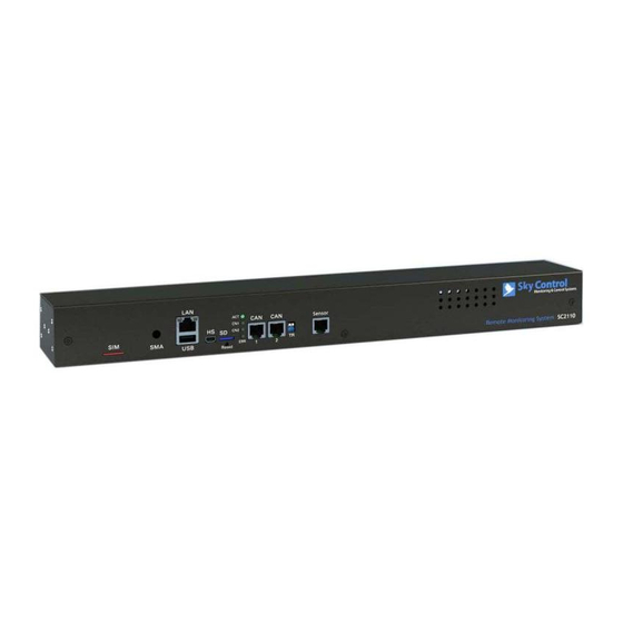
Page 11: Physical Description
Physical description Physical description Front panel SC8100 and SC8110 Front panel SC2100 and “LAN” - Ethernet 10/100 Base-T port, SC2110 provides Ethernet connection. • LEDs - “yellow” (status) and “green” (traffic) shows the network traffic. The status LED: flashes green when... - Page 12 “PWR” - for connection of external power appliance to connect SIM card. 12V. Internal input “+”. “Outputs 1..4” - 4 relays status indicators. “1-Wire” - RJ9 connector for 1-Wire Proximity type or I-touch readers with auto-sensing. Back panel SC8100 Back panel SC8110 Back panel SC2110...
- Page 13 Physical description Back panel SC2100 “Dry contacts” - empty slot for dry con- tacts module SC16, used to connect dry contacts on doors, windows, etс. “Fan sensors 1...6” - Inputs for airflow sensors. Back panel SC408 Back panel SC450 “AC line” - power input 240V. IEC C14 connector.
-
Page 14: Inventory
1.8-m EU-Schuko / C13 meet the following configuration. Report a miss- power cord ing or damaged component to your supplier. If damage occurred during transportation, contact the appropriate delivery service. SC8100, SC8110, SC2110 Inventory 1.8-m IEC C13/C14 Master module power cord... - Page 15 Package content Inventory Inventory Backup battery 3.5mm terminal plug Relay terminal plug 5.08 SC8100, SC8110, mm - 1 pc for 8 pins and SC2100, SC2110 1 pc for 4 pins 12V adapter SC8100 SC2100, SC408, SC450 CD-ROM with documen- Dry contacts board...
- Page 16 Package content Inventory Antenna SC920 Antenna wire with spac- SC920 BH16 cable SC920 Airflow sensor (TS1) - 2 SC450 Relay terminal plugs - 3 SC16...
-
Page 17: Installation
Select a place of unit installation inside the rack. The system takes up 1U of rack. Set to the The units (SC8100, SC8110, SC2110) can be desired location and tighten the bolts on the installed in the front or rear of the rack. It takes spacer nuts. -
Page 18: General Connection Of Sensors And Devices
Installation For SC8100, SC8110, SC2110, connect Connect unit’s Ethernet port using network the appropriate power cord to the unit AC cable to the switch. line input. For SC2100 plug in the power Plug the power cable into the power adapter that was in the package content. -
Page 19: Chain Connection Of Sc541, Sc560
Installation CAN sensors and CAN Type Analog sensors modules connection Vibration sensor (SC540) Connect CAN sensors to any CAN port CN1 or CN2 on the monitoring system using a CAN Vibration sensor (SC541). FTP cable supplied. CAN sensors can also be Chain connection possible. -
Page 20: Sc408 Sensor Extension Unit
I-Touch or 1-Wire Proximity readers can be con- nected to the port “1-Wire” using RJ9 (4P4C) connector. The reader is determined automati- cally. Only SC8100 and SC8110 have “1-Wire” port. Check the PCB. DIP switch 2 should be in “ON”... -
Page 21: Connecting I-Touch Button
Installation Connecting I-Touch Button Connecting Proximity reader I-BUTTON readers have two wires: Proximity readers have 3 wires: Power (+12V) Ground (GND) Ground (GND) Data wire (BUS) Data wire (BUS) Reader’s ground wire is connected to the GND Proximity reader’s GND is connected to the GND pin on RJ9 connector. -
Page 22: Connecting Relays
RLY1 ... RLY4 while connect up to 4 loads managed by built-in external voltage source is turned on. relays . In the case of SC8100 built-in relays have independent separate entrances and exits. Connecting the load to SC8110 In case of SC8110 appliance, power is applied to all inputs of 4 built-in relays. -
Page 23: Connecting Dry Contact Module
Dry contacts board BH10 cable Connecting dry contacts module SC8100, SC8110, SC2110, SC2100 have the possibility to install Dry Contacts module. It is a device mounted and connected inside of master unit. Can be used together with any contacts, Relay terminal plugs... - Page 24 Installation Installation of Dry Contacts Set up dry contacts module on 3 steel module spacing sleeves inside the appliance case, attach the board with three M3 screws Disconnect device power cable. from supply to the sleeves. Carefully unscrew three screws holding the cover and open it.
-
Page 25: Connecting Gsm Modem
Antenna wire BH16 cable Connecting GSM modem M3*5mm bolts. 3pcs SC8100, SC8110, SC2110, SC2100 have the Installation possibility to install GSM modem. The device is mounted and connected inside of master unit. Needed when network is absent or for reserva-... - Page 26 Installation Connect antenna cable to the modem board. Carefully connect the U-Fl antenna cable to the input U-FL connector and gen- tly press it. If possible install the connector on the seat with a magnifying glass! Do not tighten SMA connector with one key, you can break the cable and the con- nection would be lost! Connect 16-pin flat cable to the connectors...
-
Page 27: Connecting Backup Battery
Connecting backup battery List of USB cameras Backup battery can be connected to the fol- We recommend: lowing systems: SC8100, SC8110, SC2100, SC2110. USB + HS inputs cams: If necessary, connector “DC 12V” can be con- nected to the backup battery 10-12 V with sup- Manufacturer Art. -
Page 28: Initial Configuration
Initial Configuration Initial Configuration Connecting the device To start working with the appliance your PC must be in the same network as the System configuration and monitoring is done new appliance! To do this please set up on your through web-interface. To access the web-inter- PC: subnet mask: 255.255.255.0 and IP- face you need to enter an IP address or a name address: 192.168.0.XXX, where XXX = number... -
Page 29: User Access
To restore, to change or to clone settings, copy Com port View serial port settings the file “sky25settings.sky” to the root of a USB- Sensor data View sensor data flash drive, without changing the file name. Plug the USB flash drive into the appliance socket... -
Page 30: Password Recovery
Interface overview the version of the web interface, the current time and the operating time of the device. Control of the device is made through Sky 9. “Log bar”. To view system log Control web-interface. The general view of the interface is shown below: 10. - Page 31 Initial Configuration...
-
Page 32: Quick Configuration
Quick Configuration Quick Configuration Turn on the appliance, set up the network set- settings (including IP-address) in the root of the tings, proceed to configure other settings and USB-flash. After the LED on the USB-flash will actions. stop blinking, remove the drive from the device. Connect the USB-flash to your PC. -
Page 33: Creating Floor Map Plan
Quick Configuration Creating floor map plan To upload a map or plan , go to “System Menu” , click on “Upload / edit image maps” , select the image with the plan of your building/office and click “OK”. To place an icon on the map/plan, select the element from the tree, and drag it to the map . -
Page 34: Creating Groups Of Elements
Quick Configuration In the dialog box, specify a group name, fill in the description and press “Save”. Creating notifications Notifications are intended to inform the user about events occurring in the monitoring sys- tem. To create notification go to “Add” in the upper Creating groups of elements left corner of the interface, select the needed element. -
Page 35: Notification Via Snmp Trap
Quick Configuration Notification via SMS Parameter Description SMTP server on the cor- To create notification via SMS you have to speci- SMTP port rect port number. (e.g. 25 fy the following parameters: or 465) Login, SMTP server username Parameter Description Password and password Sender’s e-mail address... -
Page 36: Creating Ping
Quick Configuration Example. If the text has the following form: registers back to normal state. To add a ping, go to “Add” in the upper left corner of the web interface, select “Add Ping” . Ping properties window will appear. When logic is triggered and the notification is sent, the recipient will see a message in the fol- lowing form:... -
Page 37: Adding Ip Camera
Quick Configuration Adding IP camera To add, edit, deactivate or remove a logic scheme, go to “Preferences” , select “Logic” schemes” and click on the item “Add”, “Edit”, “Deactivate” or “Delete”. When editing or adding a logic scheme, specify the logic scheme name. Create a set of conditions IF. -
Page 38: Access Control
Quick Configuration reaches 36°C. If temperature reaches 44°C you Second logic scheme will turn on Fan#2 need to activate second fan and to notify the when temperature reaches 44°C. SMS administrator via e-mail and SMS. and e-mail notifications will be sent. You have: Device Description... -
Page 39: Managing Keys
Quick Configuration Managing keys • warning – occurence of a one-time error that does not affect the overall operation To edit or delete keys in the key database, go to of the GSM modem; “Preferences”, select “Access control”, select the •... -
Page 40: Sms Commands
Quick Configuration is split into several parts. In addition, this In case of an error, an SMS will be sent with field allows you to edit macros (1%-7%) information about the error and an example of which insert the real values of the variables command. -
Page 41: Sending Sms From Pc
C can be found outlet) two times with a temporary delay speci- here: fied as a “duration” parameter in seconds. ftp://ftp.sky-control.com/drivers/sms/ Examples. The zip file Adobe AIR contains application and • “set 1004 pulse 15” - pulse is sent to the an example of code in C. -
Page 42: Setting Up Can
Quick Configuration Setting up CAN made through tab “Preferences” >> “CAN con- fig”, which in turn has two identical tabs - one for each node. CAN bus is used for connection of CAN sensors Each station tab contains current information on and CAN modules. -
Page 43: Setting Up Dynamic Dns
Quick Configuration Setting up dynamic DNS Dynamic DNS is used to assign a persistent domain name to a device. The device allows to update Domain Name System to a point to a changing IP Address in automatic regime. Example of setting up Dynamic DNS service on no-ip.com: •... -
Page 44: Upgrade And Restore Options
“Network” on the device. If necessary, type in or change FTP path for the update file “sky25firmware.sky” in the field • To clear browser history in Mozilla Firefox “FTP server to upgrade”. Save the settings using follow: Tools->Clear Resent History... - Page 45 Upgrade and restore Upgrade through USB To update the software via USB, copy the update file (“sky25firmware.sky”), the system manager: Registered Windriver. Return to the settings file (“sky25settings.sky”) or/and reset unpacked folder C:\extract\ and run C:\extract\ password file (“sky25resetusers.sky”) into the skyupdater.exe file.
- Page 46 Upgrade and restore Attention! Before starting operation, make sure you press the appliance “Reset” button or turn on/off the power, otherwise the program will not be able to connect appliance. Set the appliance to «Normal» mode. In order to do this, turn off the appliance, open the cover, switch the DIP switch 1 “Recovery”...
-
Page 47: Cleaning, Battery & Fuse Disposal And Replacement
Cleaning, battery and fuse disposal and replacement Disposal Fuse replacement Sky Control appliance contains replaceable silver Use the fuse 20x5mm. oxide coin-cell battery SR44. Silver oxide batter- ies contain a small amount of mercury and can be recycled to recover it. Please take this into When replacing a fuse, it is important to account when replacing the battery. -
Page 48: Cleaning
Cleaning, disposal, replacement Attention! Make sure the plastic holder is not cold and its temperature is more than 20°C! The cold reduces the flexibility of plastic and can damage the parts. If the fuse holder is cold, then put it in a warm place for some time, if you have such possibility. -
Page 49: Warranty
Warranty Warranty Warranty is included in the appliance inventory. Please, carefully read the terms of the war- ranty. Save your warranty and the documents of sale in a safe place. These documents will be required for exercise of warranty service. Warranty period Appliance: two years from the date of original purchase. - Page 52 www.skycontrol.com wiki.skycontrol.com - Documentation forum.skycontrol.com - Support...
Need help?
Do you have a question about the SC8100 and is the answer not in the manual?
Questions and answers