Table of Contents
Advertisement
Advertisement
Chapters
Table of Contents

Subscribe to Our Youtube Channel
Related Manuals for Skanti TRP 9250


Summary of Contents for Skanti TRP 9250
- Page 1 SKANTI TRP 9250 250 Watt Radio Transceiver for MF/HF...
- Page 2 ORM=t~íí o~Çáç=qê~åëÅÉáîÉê Ñçê=jc=L=ec qÉÅÜåáÅ~ä=j~åì~ä Skandinavisk Teleindustri SKANTI A/S 4 Lautrupvang, DK-2750 Ballerup, Denmark...
- Page 3 Please note Any responsibility or liability for loss or damage in connection with the use of this product and the accompanying documentation is disclaimed. The information in this manual is furnished for informational use only, is subject to change without notice, may contain errors or inaccuracies, and represents no commitment whatsoever.
-
Page 4: Table Of Contents
Mounting the units ..........7-3 Transceiver Unit terminal strip panel ....3-23 Figures and tables ..........7-4 Final installation Check ......3-27 Installation configuration .......7-18 Configuration Prom ........3-29 Installation related ’Prog’ key operations ..3-45 Configuration ..........3-49 Installation Wiring Diagrams......3-69 TRP 9250 TECHNICAL MANUAL... - Page 5 qom=VORM=qb`ekf`^i=j^kr^i...
-
Page 6: Introduction Table Of Contents
1. INTRODUCTION Table of Contents INTRODUCTION 1. INTRODUCTION Table of Contents General Description Basic Versions Technical Data TRP 9250 TECHNICAL MANUAL... - Page 7 INTRODUCTION TRP 9250 TECHNICAL MANUAL...
-
Page 8: General Description
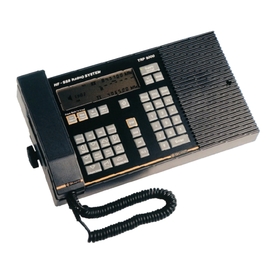
GENERAL DESCRIPTION INTRODUCTION GENERAL DESCRIPTION transmission only on these frequencies. The The TRP 9250 is a general purpose HF SSB transceiver designed for maritime applications compact Transceiver Control Unit is easily in- covering the frequency range 1.6 - 30 MHz. -
Page 9: Basic Versions
INTRODUCTION BASIC VERSIONS BASIC VERSIONS TRP 9250 Marine HF-SSB Radio System • 250 Watt P.E.P. Power Amplifier. • Simplex / Semi-duplex operation. • 896 Pre-Programmable Frequencies in the ITU Marine Bands. Free RX Frequency. • ITU Frequencies Pre-Programmed. • Labelling of Units. Transceiver Control Unit Type TCU 9000 S, Transceiver Unit Type TU 9250 S, Antenna Tuning Unit Type ATU 9250. - Page 10 Free TX Frequency Selection 1.6 - 30MHz. Free RX Frequency. • ITU Frequencies Pre-Programmed. • Labelling of Units. Transceiver Control Unit Type TCU 9002 S, Transceiver Unit Type TU 9257 S, Antenna Tuning Unit Type ATU 9250. TRP 9250 TECHNICAL MANUAL...
-
Page 11: Technical Data
Reception: Double sideband full carrier (A3E). 1 kHz with the search/fine tuning facility. TLX: Reception/Transmission: Single side- band suppressed carrier with modulating Antenna Impedance: sub-carrier (J2B). 50 ohm. Automatically matched by the An- tenna Tuning Unit. TRP 9250 TECHNICAL MANUAL... - Page 12 6 dB reduction in SINAD (SSB). after 1 min. Image Rejection: Power Reduction: Greater than 80 dB. Medium: 100 W, 60 W or 20 W (user-pro- grammable, default 60 W) IF Rejection: Low: approx. 10 W Greater than 80 dB. TRP 9250 TECHNICAL MANUAL...
- Page 13 7 - 18 m wire or whip antenna Interface Protocol: Antenna Tuning: T+Bus or NMEA 0183 Fully automatic with no presetting Total System Delay in TLX mode Tuning Speed: Ext key on to TX audio in: ≥ 5 ms 0.1 - 0.5 sec. TRP 9250 TECHNICAL MANUAL...
- Page 14 Weight: 16 kg, approx. TX H3E Alarm: 360 W Antenna Tuning Unit: Width: 290 mm BATTERY CHARGER EXTENSION Height: 504 mm Depth: 80 mm Charger type: Weight: 3.3 kg,approx. Automatic, with float charging. IE charac- teristic. TRP 9250 TECHNICAL MANUAL...
- Page 15 PRN 9000 All distances have been rounded up to the nearest 0.1 metres in order to allow for the maximum deviation which might be caused by the most offensive sample of all units manufac- tured 1-10 TRP 9250 TECHNICAL MANUAL...
-
Page 16: Operation
2. OPERATION Table of Contents Transceiver Control Unit Keys and Simplex Frequency 2-25 Annunciators Copy Rx Frequency 2-26 TCU 9000 for versions TRP 9250, Copy Tx Frequency 2-27 9251 and 9253 Store a ChanneL 2-28 TCU 9002 for versions TRP 9252... - Page 17 OPERATION 2. OPERATION Table of Contents TRP 9250 TECHNICAL MANUAL...
-
Page 18: Transceiver Control Unit Keys And Annunciators
TRANSCEIVER CONTROL UNIT KEYS AND ANNUNCIATORS OPERATION TRANSCEIVER CONTROL UNIT KEYS AND ANNUNCIATORS TCU 9000 for versions TRP 9250 S, 9251 S and 9253 S. TRP 9250 TECHNICAL MANUAL... -
Page 19: Tcu 9002 For Versions Trp 9252 And 9257
OPERATION TRANSCEIVER CONTROL UNIT KEYS AND ANNUNCIATORS CONTROL UNIT KEYS AND ANNUNCIATORS TCU 9002 for versions TRP 9252 S and 9257 S. TRP 9250 TECHNICAL MANUAL... -
Page 20: Tcu 9004 For Version Trp9254
TRANSCEIVER CONTROL UNIT KEYS AND ANNUNCIATORS OPERATION CONTROL UNIT KEYS AND ANNUNCIATORS TCU 9004 for version TRP 9254 S. TRP 9250 TECHNICAL MANUAL... -
Page 21: Tcu 9005 For Version Trp 9255
OPERATION TRANSCEIVER CONTROL UNIT KEYS AND ANNUNCIATORS CONTROL UNIT KEYS AND ANNUNCIATORS TCU 9005 for version TRP 9255 S. TRP 9250 TECHNICAL MANUAL... -
Page 22: Symbol Explanation
This symbol is printed next to additional information on the operation described above it. Flashing annunciator When an annunciator (e.g. kHz) is printed in reverse it indicates that the annunciator is flashing in the Control Unit display. TRP 9250 TECHNICAL MANUAL... -
Page 23: Power On
POWER ON Turning on the TRP 9250 Press to turn on the TRP 9250. The display will return the last set-up from when the transceiver was turned off. Select the required illumination level for the Keyboard and Display. The illumination has 4 different levels: Press to toggle the illumination level. -
Page 24: Distress Operation
DISTRESS OPERATION OPERATION DISTRESS OPERATION Using the 2182 kHz Distress mode. Press to switch on the TRP 9250. Press to select the pre-set Distress mode. Press simultaneously to transmit the Two-Tone Alarm Signal. The Alarm Signal will continue for 45 seconds or untill is pressed. -
Page 25: Test Of Alarm Generator
If TX Off is selected, only the audio part of the 2-tone Alarm Generator is tested. In some countries it is permitted to test the 2-tone Alarm Generator into dummy load in AM mode on 2200 kHz. 2-10 TRP 9250 TECHNICAL MANUAL... -
Page 26: Receiver Frequency
Enter the receiver frequency that you wish to use. e.g. 4419.4 kHz. Press to complete your frequency choise Receiver frequency range: 150 kHz to 30 MHz. The receiver display will flash if an invalid frequency is entered . TRP 9250 TECHNICAL MANUAL 2-11... -
Page 27: Audio Control
Press to turn the Squelch on and off. The Squelch will switch on the audio in periods where a voice signal is received. The Squelch annunciator will be displayed when the Squelch is on. 2-12 TRP 9250 TECHNICAL MANUAL... -
Page 28: Receiver Tuning
Tune Rate is used. Press to manually tune the receiver up or down in the programmed step. Press to return to a standard Tune Rate. The display bar will indicate which standard Tune Rate is selected. TRP 9250 TECHNICAL MANUAL 2-13... - Page 29 0.1 second - 1.0 second by pressing a numeric key. 1 corresponds to the shortest dwell-time (0.1 second) and 0 corresponds to the longest dwell-time (1.0 second). Pressing will stop Automatic Receiver Tuning. Pressing will stop Automatic Receiver Tuning and transfer current receiver frequency to the transmitter. 2-14 TRP 9250 TECHNICAL MANUAL...
-
Page 30: Automatic Gain Control
Is usefull when noise keeps comming up in signal pauses. AGC on / Automatic Minimum Signal Threshold. Press to adjust the Minimum Signal Threshold automatically. Press to remove the Minimum Signal Threshold and return to normal AGC mode. TRP 9250 TECHNICAL MANUAL 2-15... - Page 31 Press to turn the AGC off. The Sensitivity is now adjusted to the same Signal strength level as when the AGC was on. Press to adjust the Sensitivity level. Press to switch AGC on again. 2-16 TRP 9250 TECHNICAL MANUAL...
-
Page 32: Difficult Receiver Conditions
Antenna Attenuator is switched on. The Antenna attenuator should be used when strong interferring signals are present at the receiver antenna input. Strong interferring signals may distort the wanted signal by overloading the receiver input. TRP 9250 TECHNICAL MANUAL 2-17... -
Page 33: Adjust Bfo
The display will flash when the minimum or maximum BFO frequency is reached. The BFO keys can only be operated in CW mode. The BFO frequency range is 0.3 kHz to 3.0 kHz. 2-18 TRP 9250 TECHNICAL MANUAL... -
Page 34: Change Bandwidth
0.3 kHz - 2.4 kHz - 6.0 kHz - 0.3 kHz - The actual receiver bandwidth is shown shortly in the receiver display. The BW key can only be operated in CW mode. TRP 9250 TECHNICAL MANUAL 2-19... -
Page 35: Transmitter On/Off
TRANSMITTER ON/OFF Turning the transmitter on or off. Press to turn the transmitter on. The TX display will display the selected transmitter frequency. Press to turn the transmitter off. The TX display will be extinguished. 2-20 TRP 9250 TECHNICAL MANUAL... -
Page 36: Transmitter Frequency
Transceiver Unit 9251: TX frequencies in the Marine Bands ( 1.60 - 4.80 MHz, 6.20 - 8.95 MHz, 12.23 - 17.65 MHz, 18.78 - 27.10 MHz ). Transceiver Unit 9253, 9254, 9255, 9257: TX frequencies from 1.6 MHz to 30 MHz. TRP 9250 TECHNICAL MANUAL 2-21... -
Page 37: Power Level
OPERATION POWER LEVEL POWER LEVEL Changing The Transmitter Power Level on versions TRP 9250, 9251, 9253 and 9257. Press to switch from Full to Medium power. Press to switch from Medium to Low power. Press to switch from Low back to Full power. -
Page 38: New Medium Power Level
NEW MEDIUM POWER LEVEL OPERATION NEW MEDIUM POWER LEVEL Selecting a new level for Medium power on versions TRP 9250, 9251, 9253 and 9257. Press and the first option for Medium power will be displayed: 60 W. Press and the second option for Medium power will be displayed: 100 W. -
Page 39: Tune The Atu
The conditions might change during a transmission and a new tune up will be needed. For example if ice is building up on the antenna or the vessel is heeling. Press to perform a new Tune procedure. 2-24 TRP 9250 TECHNICAL MANUAL... -
Page 40: Simplex Frequency
Selecting the same frequency for both receiver and transmitter. Press to clear both the receiver and the transmitter displays. Enter the frequency that you wish to use for both receiving and transmitting. e.g.2049 kHz Press to complete your frequency choise. TRP 9250 TECHNICAL MANUAL 2-25... -
Page 41: Copy Rx Frequency
Prog and the RX Bar will flash in the display. Press to transfer the RX frequency to the transmitter. The receiver frequency is now displayed in both the RX and the TX display. 2-26 TRP 9250 TECHNICAL MANUAL... -
Page 42: Copy Tx Frequency
Prog and the RX Bar will flash in the display. Press to transfer the TX frequency to the receiver. The transmitter frequency is now displayed in both the RX and the TX display. TRP 9250 TECHNICAL MANUAL 2-27... -
Page 43: Store A Channel
Enter the channel number that you wish to use as as storage for the set-up. e.g. User Programmable channel 76. Press to enter your choise of User Programmable channel. User Programmable Channels: 100 from channel no. 0 to 99. 2-28 TRP 9250 TECHNICAL MANUAL... -
Page 44: Recall A Channel
0 - 99 : User Programmable Channels. 100 - 129 : GMDSS Distress and Safety Frequencies. 200 - 399 : Direct Recall of the first 200 of up to 896 Pre-Programmed frequencies. 401 and up: ITU Frequencies. TRP 9250 TECHNICAL MANUAL 2-29... -
Page 45: Change Mode
Press to switch to TELEX mode. Press to switch to R3E mode. For versions TRP 9250, 9251, 9253 and 9257: Press to switch to SSB mode. Where enabled - press switch to LSB mode. For versions TRP 9254 and 9255. - Page 46 CHANGE MODE OPERATION For versions TRP 9255 and 9257. Press to switch to CW mode. As standard LSB is only enabled in the Basic version TRP 9254. TRP 9250 TECHNICAL MANUAL 2-31...
-
Page 47: Channel Scanning, Set Up
2 = signal strength, 3 = squelch or signal strength, 4 = squelch and signal strength. e.g. 2. Press to store the Trigger Source. Because signal strength is selected as Trigger Source in this example, you must set the corresponding sensitivity level now. 2-32 TRP 9250 TECHNICAL MANUAL... - Page 48 Hold Time. Now the channels that you wish to scan must be stored in the Scan Table. Enter the first Channel Number to be scanned. e.g. ITU ch. 403 Press to store the channel. TRP 9250 TECHNICAL MANUAL 2-33...
- Page 49 Enter the third Channel Number to be scanned. e.g. ch. 76 from the User Programmable Memory. Press to store the channel. When the last channel is stored, the transceiver will return to normal operation. 2-34 TRP 9250 TECHNICAL MANUAL...
-
Page 50: Channelscanning, Set Up Info
If you store a bigger number of channels than required TRP 9250 will reduce the alocated memory to the actual need, after the scan table has been stored and then update the Number Of Channels to be scanned to the actual number. - Page 51 Channel Number: An ITU channel or a channel stored in the User Programmable Memory. View parameters and channels of a Scan Program: Press Delete a channel: Store 9999 as Channel Number in the scan table position that you wish to delete. 2-36 TRP 9250 TECHNICAL MANUAL...
- Page 52 Replace a channel: Store the new Channel Number in the position of the channel you want to replace. Leave a Scan Program: You may leave the programming at any time by pressing Remote Scan start/stop facility: Is available with optional radiotelex modem "PCP717tlx" or remote control interface "Interface-A 718" installed. TRP 9250 TECHNICAL MANUAL 2-37...
-
Page 53: Channel Scanning, Recall Program
Trigger Sourse = Signal Strength (2) Number of Channels to be scanned = 3 Dwell time = 2.5 seconds Hold Time = 20 seconds Press to return. The Transceiver will now return to normal operation. 2-38 TRP 9250 TECHNICAL MANUAL... -
Page 54: Channel Scanning,Start/Stop
Table when you press again. Receiver and Transmitter frequency of the channel which was displayed when you stopped the scanning will now be displayed. e.g. User Programmable channel 76: RX= 4143.6 kHz and TX= 6218.6 kHz. TRP 9250 TECHNICAL MANUAL 2-39... -
Page 55: Frequency Sweeping, Setup
Sensitivity -80 dB. Press to store the level. Enter the Dwell Time which is the period in which the receiver will "listen" for a signal on each frequency. e.g. 2.5 seconds. Press to store the Dwell Time. 2-40 TRP 9250 TECHNICAL MANUAL... - Page 56 3.1 kHz. Press to store the Step Frequency. Enter the Start Frequency . e.g. 8718.9 kHz. Press to store the Start Frequency. Enter the Stop Frequency . e.g. 8811.9 kHz. Press to store the Stop Frequency. TRP 9250 TECHNICAL MANUAL 2-41...
-
Page 57: Frequency Sweeping, Set Up Info
Start Frequency : The first frequency in the Sweep Band. Stop Frequency : The last frequency in the Sweep Band. Remote Sweep start/stop facility: Is available with optional radiotelex modem "PCP717tlx" or remote control interface "Interface-A 718" installed. 2-42 TRP 9250 TECHNICAL MANUAL... -
Page 58: Frequency Sweeping Start/Stop
Press to stop the frequency sweep. Sweeping will start on the first frequency in the band when you press again. The Receiver frequency which was displayed when you stopped the Sweep will now be displayed. TRP 9250 TECHNICAL MANUAL 2-43... -
Page 59: Sleep Timer, Set Up
1. Press to store your choise. Enter the Channel Number that you whish to use when the Sleep Program turns on the transceiver. e.g. ITU channel 802. Press to store the Channel Number . 2-44 TRP 9250 TECHNICAL MANUAL... - Page 60 15.30 (3.30 PM). Press to store the Fall Asleep Time. When the Fall Asleep Time is stored, the transceiver will return to normal operation. Note: TRP 9250 TECHNICAL MANUAL 2-45...
-
Page 61: Sleep Timer Info
Fall Asleep Time: At this time the Sleep Program will switch off the transceiver. Wake Up and Stay On: If the the Fall Asleep time is set to the same time as the Wake Up time the Transceiver will switch on and stay on at this time. 2-46 TRP 9250 TECHNICAL MANUAL... -
Page 62: Sleep Timer On
Sleep Timer is deactivated as described above. NOTE. Sleep and DSC/Telex operation If TRP 9250 includes the optional built-in DSC/Telex the Sleep function is modified to a pseudo- Sleep function complying with the GMDSS requirements on DSC/Telex distress operation as follows. -
Page 63: Operations
Flash the ":" symbol of the watch and respond to all keying, key entries and remote control commands. The TRP 9250 will disable the pseudo-Sleep and return to normal operation on a remote control command, keying and key entry except RX-freq./mode command, volume up/down and speaker (scanning of RX DSC or Telex frequencies via PCP 717S will not disable pseudo-Sleep). -
Page 64: Operation Related 'Prog' Key Operations
Set Break-in Time for CW. Switch RF Attenuator On/Off. Float Antenna. Ground Antenna. Switch "Boop" Sound On/Off. Select Intercom. Set Real Time Clock. Switch Treble Cut On/Off Tilt Viewing Angle of Display. Toggle Bar-graph Reading, Power or Amperes. TRP 9250 TECHNICAL MANUAL 2-49... - Page 65 Switch Beep Sound On. Switch Boop Sound On. Switch High-beep Sound On. Display Customer Secified Frequencies Pre-Programmed in Configuration PROM. Display Configuration parameters pre-programmed in Configuration PROM. View Supply Voltage View and Change Security Code. Select Configuration Mode. 2-50 TRP 9250 TECHNICAL MANUAL...
- Page 66 "STO" to store the wanted level and to return to the normal display. If "Enter" is pressed instead the old Side Tone frequency and level are retained and the transceiver will return to normal display. Both Side Tone frequency and level are adjustable during transmit condition. TRP 9250 TECHNICAL MANUAL 2-51...
- Page 67 Transceiver can neither receive nor transmit.Press "Enter" to return to normal operation. Switch "Boop" sound On/Off . If an illegal key is pressed the CU will sound a "Boop". This feature may be selected / inhibited to suit the individual operator. 2-52 TRP 9250 TECHNICAL MANUAL...
- Page 68 OPERATION RELATED ’PROG’ KEY OPERATIONS OPERATION Select Intercom. When more than one Control Unit is connected the TRP 9250 can act as a normal telephone with intercommunication between any two control units.After "Prog" "10" "Enter" is pressed the display shows Phone _ Enter "phone number"...
- Page 69 Security Code only when the ship is in port and disable the Security Code when the ship is at sea, giving quick radio-access to all on board in case of an emergency situation. 2-54 TRP 9250 TECHNICAL MANUAL...
-
Page 70: Propagation Of Hf And Mf Radiowaves
Introduction The TRP 9250 is able to operate on frequencies from 1.605 MHz to 30 MHz. This frequency span covers the upper part of the MF range (0.3 - 3 MHz) and the whole HF range (3 - 30 MHz). - Page 71 During periods of high solar activity the MUF will be higher, but at the same time disturbances in the Ionosphere, due to the high activity, will be more frequent. Tables of MUFs covering various radio paths are published monthly by many telecom administrations. 2-56 TRP 9250 TECHNICAL MANUAL...
-
Page 72: Connectors
3-40 Reset currently used Control Unit 3-67 Standard Programming 3-44 Reset SystemParameters to 3-67 default values Installation related ’Prog’ key 3-45 Reset total memory and system 3-67 operations parameters to default values View / changePassword 3-68 TRP 9250 TECHNICAL MANUAL... - Page 73 INSTALLATION 3. INSTALLATION Table of contents TRP 9250 TECHNICAL MANUAL...
-
Page 74: Mounting The Units
DESCRIPTION General Correct installation of the TRP 9250 is important for maximum performance and reliability. Antennas and earth connections must be installed with the greatest care using corrosion resistant materials. Cable routing shall be made so the cables are protected from physical damage. Sharp cable bends especially on coaxial cables must be avoided and a sufficient number of clips or straps should be used to secure the cables. -
Page 75: Installation Mounting The Units
INSTALLATION MOUNTING THE UNITS Installation examples and recommended cable specification including the DSC option. Cable type: 2 x 5 screened multiwire ScanBus termination jumper: TRP 9250 TECHNICAL MANUAL... - Page 76 2) Space for cable entry and handset cable: min. 200 3) Space for cable entry: min 50 4) For tilted mounting: drill 4 holes Ø8 in bottom of cabinet Dimensions are in mm Tolerance: +/- 1 mm Weight: 3.4 Kg fig.2 Doc.: 4-0-31441 Mounting options TRP 9250 TECHNICAL MANUAL...
- Page 77 The viewing angle of the LCD display can be optimized for best performance by using the ’Prog’ ’13’ function. The level of the Beep sound (when pressing a key) may be adjusted by pressing ’Prog’ ’@’ function. See description of the User Programmable Functions. TRP 9250 TECHNICAL MANUAL...
-
Page 78: Mounting The Units
3) Space for service access: min. 1000 Dimensions are in mm Tolerance: +/- 1 mm fig.6 Weight without optional AC power supply: 19.5 Kg Weight with optional AC power supply: 21 Kg Mounting options Centre of gravity Doc.: 4-0-34091 TRP 9250 TECHNICAL MANUAL... - Page 79 2) Space for service access: min. 1000 Dimensions are in mm Tolerance: +/- 1 mm Weight without optional AC power supply: 19.5 Kg Weight with optional AC power supply: 21 Kg Centre of gravity Doc.: 4-0-34088 TRP 9250 TECHNICAL MANUAL...
-
Page 80: Mounting The Antenna Tuningunit
1) Space to nearest overhang: min. 50 2) Space for service access: min. 500 3) Space for cable and service access: min. 200 Dimensions are in mm Tolerance: +/- 1 mm Weight: 3.3 Kg Doc.: 4-0-34106 fig.9 Mounting options TRP 9250 TECHNICAL MANUAL... -
Page 81: Powersupply
Connection Board. The fuse is accessed by pulling out the black handle, The correct fuse rating for each voltage setting is as follows Setting Fuse rating 8 A Slow 4 A Slow Fuses are cartridge type measuring 20 x 5 mm. 3-10 TRP 9250 TECHNICAL MANUAL... - Page 82 Maximum possible peak voltage betweeen the battery terminals and earth is 100 V. Note that fuses must be provided in the supply leads. A table on the previous page shows the necessary cable cross sections and external fuse ratings. TRP 9250 TECHNICAL MANUAL 3-11...
-
Page 83: Battery Charger
Two temperature sensors may be connected to the Charger Control Board for temperature compensation, one for the float charging voltage, the other for the independent High Voltage Alarm 3-12 TRP 9250 TECHNICAL MANUAL... - Page 84 Temperature Sensor input for high voltage alarm. Terminal Designation Description Temperature sensor input for battery tempera- ture compensation. Jumper must be moved to TS2 ON when used. Important: When temperature sensors are not installed, jumpers must be in Off position. TRP 9250 TECHNICAL MANUAL 3-13...
-
Page 85: Earth Connections
The Transceiver Unit is preferably grounded separately to the ships metal in the shortest possible way. A 10 to 16mm sq. ground wire is connected to the ground terminal (cable clamp) at the bottom of the unit. On vessels with no metallic superstructure the ground connection may be omitted. 3-14 TRP 9250 TECHNICAL MANUAL... -
Page 86: Antennas
This will prevent bad connections due to corrosion. For further corrosion proofing silicone grease may be applied to the cable joints. fig.12 Cable strain relief Copper strap fig.13 Mount the ATU on a custom-built bracket made from iron angle bars TRP 9250 TECHNICAL MANUAL 3-15... -
Page 87: Interconnection Of Units
HANDSET CON Designation Remarks Terminal no. HOOK ON Low when handset is placed in the holder HANDSET KEY Low when handset key is pressed +12V 0-1.6Vpp Adjustable +/-8dB. EARPIECE Max. 2.1Vpp 3-16 TRP 9250 TECHNICAL MANUAL... -
Page 88: Transceiver Controlunit-To
Screen connected to System GND. The ScanBus termination jumper must be inserted (pos. 1) if the unit is at the end of the chain - or removed (pos.2) if the unit is not at the end of the chain. TRP 9250 TECHNICAL MANUAL 3-17... -
Page 89: Transceiver Unit-To-Antennatuning
0/24V System GND NOTE: TRP 9250 may be operated without the ATU 9250. Just connect the 50 ohms antenna system to the coaxial socket marked "TX/RX" at the Transceiver Unit . Important: In installations with long earth straps to the Antenna Tuning Unit, high RF voltages may be present on the ATU ground terminal. -
Page 90: Connectors For External Equipment
Input. Data Carrier Detected or Scan S/S Input. Receive Data. Output. Transmit Data. No connection. RCI-GND Galvanic isolated ground return for Remote Control Interface. Not connected to system ground No connection. Input. Ring indicator. Screen Cable screen. Connected to system ground. TRP 9250 TECHNICAL MANUAL 3-19... - Page 91 Adjustable from -15 dBm to +10 dBm. Line Out C Line Out - ’Key’ Galvanic isolated external key input. Pulled up to +12V. Active when pulled down to RCI-GND. RCI-GND No connection. Screen Cable screen. Connected to system ground. 3-20 TRP 9250 TECHNICAL MANUAL...
-
Page 92: External Speaker
Output. 5 watt into 8 ohms. 4 ohms speaker may be connected. SPK- Headphone for CW operation ’Headphone’. Stereo jack female . Designation Description H-phone+ Output. Hot left and right headphone drive signal. H-phone+ H-phone- Output. Common left and right headphone drive signal. TRP 9250 TECHNICAL MANUAL 3-21... - Page 93 INSTALLATION CONNECTORS FOR EXTERNAL EQUIPMENT Morse Key for CW operation ’Morse Key’. Mono jack female Designation Description Morse Key Input. Pulled up to +12v. Activated when connected to system ground 3-22 TRP 9250 TECHNICAL MANUAL...
- Page 94 The interface is opto-isolated with driver power delivered from PC DTR, 5 - 15 V. (Non-isolated: Insert jumpers J8, J9 and J13 on PCB 717S) PCB 718S installed: Remote control interface for radio control using T+Bus or NMEA protocol. TRP 9250 TECHNICAL MANUAL 3-23...
- Page 95 5 seconds and released within 10 seconds. ’Alarm 1’ Distress Lamp output. Open collector (RS-410N). Max 50 mA, 32 V. Connects to GND when active. +24V Output. Max 50 mA. Internally protected. 3-24 TRP 9250 TECHNICAL MANUAL...
- Page 96 However the shield should be continuous (unbroken) between all listeners. Following NMEA 0183/IEC 1162 sentences are recognized by the equipment for extraction of position and associated time information: GGA, GLL, GXP, GDP, GLP, GOP. TRP 9250 TECHNICAL MANUAL 3-25...
- Page 97 Designation Description 21.6 - 31.2 v output. Max 5 A total for both terminal strips. Protected by 5 A fuses in both + and -. Galvanically connected to battery Must not be connected to GND 3-26 TRP 9250 TECHNICAL MANUAL...
-
Page 98: Final Installation Check
Synthesizer Board 911. Loosen the two screws of the module and remove it. Locate the shielding box on the PCB containing the Master Oscillator. Remove the box lid and exchange Master Oscillators. Reassemble the Transceiver in the reverse order. TRP 9250 TECHNICAL MANUAL 3-27... - Page 99 INSTALLATION 3-28 TRP 9250 TECHNICAL MANUAL...
-
Page 100: Configuration Prom
CONFIGURATION PROM INSTALLATION CONFIGURATION PROM The TRP 9250 series Configuration PROM contains frequencies, frequency bands and system configuration parameters for customizing the equipment. Legal frequencies with corresponding legal mode and frequency bands are programmed in the PROM address area from 256d/0100h to 7167d/1BFFh. The PROM area is divided into three sub-areas, each with a specific frequency information and representation. - Page 101 255d / FFh xxxx xxxx 5119 13FF 5120 1400 ITU Channels ( SSB ) ITU DSC and Telex TX Frequencies xxxx xxxx Limiter Byte 255d / FFh 7167 1BFF 7168 1C00 System Configuration Parameters 8191 1FFF 3-30 TRP 9250 TECHNICAL MANUAL...
-
Page 102: Frequency Record Format
Transmitter part of duplex frequency Simplex frequency Single receiver frequency which can be recalled with a short-number Single transmitter frequency which can be recalled with a short-number Empty channel which occupy a short-number Always set to 0. TRP 9250 TECHNICAL MANUAL 3-31... -
Page 103: Fixed Step Frequencies Format
Step Frequency BCD X 10kHz BCD X 1kHz n+10 BCD X 100Hz BCD X 10Hz A large group of frequencies with uniform channel spacing are easily represented by programming the 11-byte Fixed Step Frequencies Format. 3-32 TRP 9250 TECHNICAL MANUAL... - Page 104 Number Of Channels: The total number of frequencies or channels in the group. Legal numbers: 1 to 9998. Start Frequency: The first frequency in the group. Step Frequency: The fixed frequency- or channel-spacing for the group. TRP 9250 TECHNICAL MANUAL 3-33...
-
Page 105: Frequency Band Format
If the programmed Frequencies and possible Frequency Bands do not use all the available bytes in the relevant PROM areas a Limiter Byte must be programmed to indicate the end of frequency information. The Limiter Byte contains the value 255d / FFh. 3-34 TRP 9250 TECHNICAL MANUAL... -
Page 106: Pre-Programmed Itu Frequencies
May be recalled directly by entering the relevant number from 100 to 129. Mode will automatically be set according to the table. TRP 9250: Subsequent selection of other modes will disable the transmitter except when the mode is SSB and R3E is selected. - Page 107 May be recalled directly by entering ITU channel number. Mode will automatically be set to SSB. TRP 9250: Subsequent selection of other modes except R3E will disable the transmitter. Inter-ship SSB Simplex frequencies in the Maritime Mobile Bands between 4 and 27.5MHz.
- Page 108 May be recalled directly by entering channel number. Mode will automatically be set to SSB. TRP 9250: Subsequent selection of other modes except R3E will disable the transmitter. Ship station SSB TX frequencies in the 8100 - 8195kHz band. Successive channel numbers are assigned.
- Page 109 INSTALLATION CONFIGURATION PROM Extra frequencies for TRP 9250: National ship station MF DSC TX frequencies for purposes other than distress and safety. 2156.0 2156.5 kHz 2157.0 2157.5 kHz 2158.0 2158.5 kHz 2159.0 2159.5 kHz 8 TX frequencies For verification of TX frequency only. TX frequencies are only selectable in Telex mode. Subsequent selection of other modes will disable the transmitter.
- Page 110 CONFIGURATION PROM INSTALLATION Extra frequencies for TRP 9250: Ship station non-paired NBDP frequencies in the Maritime Mobile Bands between 4 and 27.5MHz. ITU Radio Regulations Apendix 33. Non-paired Telex Frequencies. 4MHz Band 1 - 10 6MHz Band 1 - 23...
-
Page 111: Systemconfiguration Parameters
Maximum TX power = 20 x Pm W Pm = values from 1d/01h to 25d/19h corresponds to 20Watt to 500Watt Security Code Enable 7602d/1DB2h 0d/00h: Disable Security Code 1d/01h: Enable Security Code All other data are defaulted to 1d/01h 3-40 TRP 9250 TECHNICAL MANUAL... - Page 112 7608d/1DB8h 0d/00h: Disable R3E mode 1d/01h: Enable R3E mode All other data are defaulted to 1d/01h Enable CW mode 7609d/1DB9h 0d/00h: Disable CW mode 1d/01h: Enable CW mode All other data are defaulted to 1d/01h TRP 9250 TECHNICAL MANUAL 3-41...
- Page 113 3d/03h: AM mode when 2182 is pressed All other data are defaulted to 3d/03h Receiver frequency 7616d/1DC0h status 0d/00h: RX on PROM frequencies only 1d/01h: Free RX frequency All other data are defaulted to 1d/01h 3-42 TRP 9250 TECHNICAL MANUAL...
- Page 114 TX on PROM frequencies only 1d/01h: Free TX frequency All other data are defaulted to 1d/01h Single sideband 7618d/1DC2h mode display 0d/00h: Display upper-sideband as USB 1d/01h: Display upper-sideband as SSB All other data are defaulted to 1d/01h TRP 9250 TECHNICAL MANUAL 3-43...
-
Page 115: Standard Programming
7614d/1DBEh 1d/01h 1d/01h 1d/01h 255d/FFh 255d/FFh 1d/01h 7615d/1DBFh 3d/03h 3d/03h 3d/03h 3d/03h 3d/03h 3d/03h 7616d/1DC0h 1d/01h 1d/01h 1d/01h 1d/01h 1d/01h 1d/01h 7617d/1DC1h 0d/00h 1d/01h 1d/01h 1d/01h 1d/01h 1d/01h 7618d/1DC2h 1d/01h 1d/01h 1d/01h 0d/00h 0d/00h 1d/01h 3-44 TRP 9250 TECHNICAL MANUAL... -
Page 116: Configuration
To make a reconfiguration of a Function with parameters enter the number of the Function in the Transmitter Display. Press "Function No." The current corresponding parameters are displayed in the Receiver Display with a flashing bar below the first parameter to be changed. TRP 9250 TECHNICAL MANUAL 3-49... -
Page 117: Directly Executable Functions
INSTALLATION CONFIGURATION to store the same value again if no change is wanted, or use the numeric keys to change the value and to store a change. If the Function has more than one parameter the flashing bar will shift right to the next parameter. When the last parameter has been stored another Function Number may be entered as described above. - Page 118 "Loudspeaker" key Disable/Enable Volume keys Disable/Enable Scan key Disable/Enable Sweep key Disable/Enable Sleep key Disable/Enable "Light" key Disable/Enable Att key Disable/Enable "Hidden keys": "Prog 2" (LSB) Disable/Enable "Prog 3" (R3E) Disable/Enable "Prog 16" (HST) Disable/Enable TRP 9250 TECHNICAL MANUAL 3-51...
- Page 119 INSTALLATION CONFIGURATION Keyboard keys: TRP 9254 with standard Transceiver Control Unit. No. 1 to 32."1" will enable the key. "0" will disable the key. Double keys (Tune, Rate, Sensitivity, Volume and AGC) are displayed simultaneously with a position in the display corresponding to the keyboard layout. Default values shown.
- Page 120 Disable/Enable LSB key Disable/Enable Att key Disable/Enable CW key Disable/Enable Full key Disable/Enable Med key Disable/Enable Low key Disable/Enable BW key Disable/Enable BFO keys Disable/Enable "Hidden keys": "Prog 3" (R3E) Disable/Enable "Prog 16" (HST) Disable/Enable TRP 9250 TECHNICAL MANUAL 3-53...
- Page 121 INSTALLATION CONFIGURATION Keyboard keys: TRP 9252 and TRP9257 with standard Transceiver Control Unit. No. 1 to 34."1" will enable the key. "0" will disable the key. Double keys (Tune, Rate, Sensitivity, Volume and AGC) are displayed simultaneously with a position in the display corresponding to the keyboard layout. Default values shown.
-
Page 122: Enable Powerlevels
No. 52. Select Transmitter Key Input versus transmitter mode. "0": External Key active. See function no. 73. "1": Handset Key active. "2": Both key inputs active. The keying Key excludes the other. Default values Receiver Display TX Mode Parameter Key Input TRP 9250 TECHNICAL MANUAL 3-55... -
Page 123: Agc Parameters Versus Rx Mode
INSTALLATION CONFIGURATION Compressor Time Constant versus TX Mode No. 53. Select Time Constant for the transmitter AF compressor versus transmitter mode. "1" corresponds to a normal time constant. "0" corresponds to a long time constant. Default values Receiver Display TX Mode Parameter Time Constant AGC Parameters versus RX Mode... - Page 124 Default values Receiver Display RX Mode Parameter Hang Time No. 58. Select AGC Suppressor function versus receiver mode. "1": Activate the AGC Suppressor. "0": Disable the AGC Suppressor. Default values Receiver Display RX Mode Parameter Suppressor TRP 9250 TECHNICAL MANUAL 3-57...
-
Page 125: Split Mode Disable/Enable Tables
INSTALLATION CONFIGURATION No. 59. Select additional AGC Filter. "1": Disable the additional AGC Filter. "0": Enable the additional AGC Filter. Default values Receiver Display RX Mode Parameter AGC Filter AF Bandwith No. 60. Select AF Bandwidth in telex mode. "1" corresponds to a large AF bandwidth. "0"... -
Page 126: Disable /Enable "Prog" Functions
Disable / Enable "Prog" "98" function No. 70. Disable/Enable view and change of the Security Code. "1" makes it possible to view and change Security Code. "0" makes it impossible to view or change Security Code. Default value is "1". TRP 9250 TECHNICAL MANUAL 3-59... -
Page 127: Tcu Backlight Step Mode
INSTALLATION CONFIGURATION TCU backlight step mode No. 71. Select TCU backlight step mode "0" Selects sawtooth shaped backlight step mode. "1" Selects triangle shaped backlight step mode. External "Line, key" input versus TX mode See also functions no. 51 and 52 No. - Page 128 "Remote" annunciator in the display. TRP9250 will at all time respond to all manual key entries. The "Remote" annunciator is then switched off indicating that the last entry was made manually. TRP 9250 TECHNICAL MANUAL 3-61...
- Page 129 To reenter control from the Radio-Telex modem and hence allow scanning again, press the "TLX" key. TRP 9250 will automatically return to "Autotelex with telephony option" if a transmitter frequency command is received from the Radio-Telex modem.
- Page 130 When the "2182" key is pressed, TRP9250 will enter the distress mode and ignore all commands except a transmitter frequency command, which will make the TRP 9250 return to remote controlled mode. A return from distress mode to remote controlled mode may also be performed by pressing the "TLX"...
- Page 131 INSTALLATION CONFIGURATION View / change External Scan S/S input With the optional board, Interface-A 718S, installed the available Scan S/S ( Scan Start/Stop ) input can be used to control the scanning of the 10 build-in user-programmable scan programs or the user-programmable sweep program.
- Page 132 Control is automatically transferred to the TCU where the last key entry was made. The "Busy" annunciator is switched off in all TCU’s indicating that operation can take place on any TCU. (Busy switched off in all TCU’s except when a Master Priority TCU is in use). TRP 9250 TECHNICAL MANUAL 3-65...
- Page 133 INSTALLATION CONFIGURATION PRIVACY By enabling/disabling Privacy the received signal and information displayed in the TCU’s can be controlled. This enables either normal use where the communication can be followed in another room, or private conversation. When Privacy is disabled all key entries are reflected in all displays and the received signal is led to all TCU’s.
- Page 134 The System Parameters are those listed under function number 1 to 94. Reset total memory and system parameters to default values No. 98 Function number 98 deletes the total user-programmable channel memory, executes function number 95 and 97, and resets the Password for the Configuration Mode. TRP 9250 TECHNICAL MANUAL 3-67...
- Page 135 INSTALLATION CONFIGURATION View / change Password No. 99 To prevent unauthorized programming of the configuration, the Configuration Mode may be protected with a Password. As default the Password is 0 which requires no confirmation when selecting Configuration Mode. The Password may be viewed or changed by selecting Function Number 99.
- Page 136 INSTALLATION WIRING DIAGRAM FOR TRP9250SD6T Page 1 of 2 ATU9250 TU9250SD6T DSC Antenna ATU Com TX/RX DSC RX TX/RX PRN/RCI Line,Key ScanBus Termination Note 1 - 24V + Battery -24V DC+ Alarm 24V/5A NMEA 115/230 V AC ScanBus ScanBus Remote (Optional AC Power Supply/Battery Charger) 24 DC Supply Input/...
- Page 137 INSTALLATION WIRING DIAGRAM FOR TRP9250SD6T Page 2 of 2 PC9000 DCU9000 TCU9000 HF-SSB RADIO SYSTEM TRP 9000 Supply On/Off MF/HF DSC CONTROLLER-RECEIVER DSC 9000 Sleep On/Off Press Both To Send Test Stop Power Prog STO Scan Alarm Alarm Tune Level NMO PQR Supply Main Menu...
-
Page 138: Technical Description
Power Amplifier 721 742 (option) Marine Filters 726 / Continuous Filters 927 Block Diagrams DC Power Supply/Interface Board 935 Connection Board 936 AC Power Supply Board 958 (optional) 4-6 Charger Control Board 959 Interface-A 718 (option) TRP 9250 TECHNICAL MANUAL... - Page 139 TECHNICAL DESCRIPTION 4. TECHNICAL DESCRIPTION Table of Contents TRP 9250 TECHNICAL MANUAL...
-
Page 140: Transceiver Control Unit 9000
AF lines, amplifying AF signals for the earpiece, the internal and external speaker and the line output. The connector for external speaker, phone and morse key is located on this board. TRP 9250 TECHNICAL MANUAL... -
Page 141: Transceiver Unit Tu 9250
The RX signal path includes protection, antenna attenuator, RF- and IF amplifiers, mixers, filter bank, demodulator, squelch and audio line drivers. The RX signal path performs the handling of the received antenna signal and delivers an AF signal to the control unit via DC Power Supply/Interface TRP 9250 TECHNICAL MANUAL... - Page 142 Board 717. A protection circuit switches the SMPS off in the event of an output overload and switches on again when the overload condition has been removed. The DC supply voltage is sensed by a BAT INFO detector circuit and fed to the TU Control Board for automatic RF output power adjustment. TRP 9250 TECHNICAL MANUAL...
- Page 143 The optically isolated data drivers/receivers are for control of the transceiver from an external modem. Galvanically isolated balanced 600 ohms input and output lines are available for transfer of the AF signals with a +/- 10 dB adjustment possibility of the AF output. TRP 9250 TECHNICAL MANUAL...
-
Page 144: Programmable Communication
2. IF frequency of 455 kHz. The 2. IF filter is a narrow-band crystal filter. In the 3. mixer the IF signal is mixed with 456.7 kHz producing an AF signal centred around 1.7 kHz. TRP 9250 TECHNICAL MANUAL... -
Page 145: Antenna Tuning Unit Atu 9250
The Dummy Load/Antenna Amp 942 includes relays, load resistors, and an RX-amplifier for fre- quencies below 1.6 MHz. It permits two-tone alarm generator test into Dummy Load to be performed as well as grounding or floating the antenna. TRP 9250 TECHNICAL MANUAL... - Page 146 TU CONTROL Digital Interface CPU and Memory Analog Interface and Peripherals SYNTHESIZER Ref. MASTER OSCILLATOR 17.8176 MHz Digital Divider Control OCXO 1. LO 2. LO 3. LO 45-70 MHz 44.544 MHz 456.5 kHz RX / EX RX IF Demodulator Compressor and AF circuit Digital EX IF...
- Page 148 PROGRAMMABLE COMMUNICATION PROCESSOR Processor Data Drivers Alarms and Demodulators Audio I/O and and Memory /Receivers Timers and Modulator Control Data Com TELEX MODEM - DSC/TELEX MODEM BLOCK DIAGRAM SINGLE CHANNEL RECEIVER MASTER OSCILLATOR OCXO 1:10 1:16 17.325 MHz 7.2528 MHz Demodulator RX IF and AF circuit...
-
Page 151: Service
Method 2: Realignment using the Execution Of The Manual 5-27 built-in ’Frequency Error’ test Stepped Selftest Description Of Test Steps 5-28 Replacement of Backup Battery Cleaning the Air Filter Trouble Shooting Power Protection Service related ’Prog’ key 5-17 operations TRP 9250 TECHNICAL MANUAL... - Page 152 SERVICE 5. SERVICE Table of contents TRP 9250 TECHNICAL MANUAL...
-
Page 153: Preventive Maintenance
SERVICE PREVENTIVE MAINTENANCE Due to the modern design of the TRP 9250 preventive maintenance can be reduced to a minimum provided the equipment is correctly installed. To ensure maximum performance and minimum repair trouble we recommend you to follow the below stated headlines for preventive maintenance. -
Page 154: Method 2: Realignment Using The Built-In 'Frequency Error' Test
If an AM broadcast station is used, select AM mode and observe that the signal is received with not too strong fading and a reasonable signal to noise ratio. If these requirements are not fulfilled choose another station. TRP 9250 TECHNICAL MANUAL... -
Page 155: Replacement Of Backup Battery
Refit the top cover. Replacement of Backup Battery TRP 9250 uses standard 1.5 V alkaline batteries to back-up the memory when the power supply is switched off. Use only the best quality for replacement to avoid leakage. Skanti recommends:... -
Page 156: Cleaning The Air Filter
Cleaning the Air Filter TRP 9250 uses a fan to cool the circuitry inside the Transceiver Unit. To keep the cooling air clean an Air Filter is placed behind the fan. The Air Filter should be cleaned frequently, especially under dusty working conditions. -
Page 157: Trouble Shooting
SERVICE TROUBLE SHOOTING If a malfunction should occur in the TRP 9250, the following instructions should be followed in order to locate the module which is causing the malfunction : If possible execute the built in selftest. An ’Error Code’ for the failing module will be displayed. -
Page 158: Power Protection
POWER PROTECTION POWER PROTECTION The TRP 9250 Power and Protection system is monitoring the transmitter circuits during transmission and will automatcally maximize the radiated power to safe limits. If a problem occurs the flashing ’Protec’ annunciator on the Control Unit display shows that protection is activated. The... - Page 159 TU Control Board measures too high power output. ALC power was too high. Protection made: Exciter level set to ~+12dBm. Display: Flash "Protec". Supply failure Measurement: Supply voltage high. Protection made: TX key inbitit. Display: Flash "Protec". TRP 9250 TECHNICAL MANUAL...
- Page 160 Power set as Low as possible. Display: Flash "Protec". Full High Measurement: TU Control Board measures too high power output. Full Power was too high. Protection made: Automatic power regulation inhibited. Display: Flash " Protec". 5-10 TRP 9250 TECHNICAL MANUAL...
- Page 161 Note: It is necessary to select low power or to switch off the equipment to reset the protection High Average Measurement: Average power reduced to 100W. Possible cause: CW keyed for more than 1 minute. TRP 9250 TECHNICAL MANUAL 5-11...
- Page 162 External "TX Inhibit" input is activated. Action made: TX key inhibit. PA SWR Measurement: PA SWR was high. Protection made: Output power reduced to safe limits. Possible cause: High SWR or change in antenna impedance. 5-12 TRP 9250 TECHNICAL MANUAL...
- Page 163 ATU selects feed through setting. Display: Flash "Protec". Possible cause: Bad antenna impedance on the selected frequency. High SWR Measurement: ATU measured SWR >3 but <8 during Tune Procedure. Possible cause: Poor antenna impedance on the selected frequency. TRP 9250 TECHNICAL MANUAL 5-13...
- Page 164 Poor antenna impedance on the selected frequency. V or I high TX Measurement: ATU measured that the maximum voltage or current rating is reached during transmission. Possible cause: A short antenna and a low frequency. 5-14 TRP 9250 TECHNICAL MANUAL...
- Page 165 ALC adjustment and the power had to be reduced more than 6 dB. Possible cause: A bad antenna and a low frequency. TU-ATU com bad Measurement: TU - ATU communication isnot operating. Protection made: Key inhibit. Display: Flash "Protec". Possible cause: TU - ATU communication problem. TRP 9250 TECHNICAL MANUAL 5-15...
- Page 166 SERVICE POWER PROTECTION 5-16 TRP 9250 TECHNICAL MANUAL...
-
Page 167: Service Related 'Prog' Key Operations
Switch RF Attenuator On/Off. Float Antenna. Ground Antenna. Switch "Boop" Sound On/Off. Select Intercom. Set Real Time Clock. Switch Treble Cut On/Off Tilt Viewing Angle of Display. Toggle Bar-graph Reading, Power or Amperes. Set Beep Level. TRP 9250 TECHNICAL MANUAL 5-17... - Page 168 Switch Beep Sound On. Switch Boop Sound On. Switch High-beep Sound On. Display Customer Secified Frequencies Pre-Programmed in Configuration PROM. Display Configuration parameters pre-programmed in Configuration PROM. View Supply Voltage View and Change Security Code. Select Configuration Mode. 5-18 TRP 9250 TECHNICAL MANUAL...
- Page 169 12 relay settings, the remaining 3 relay settings and finally the current limit values in amperes, obtained from one of the three current detectors. Pressing "Enter" once more will make a return to normal operation. TRP 9250 TECHNICAL MANUAL 5-19...
- Page 170 View ATU Software version, release and release date. Displays ATU software version and release date. Receiver Display: Version and Release number as VV.RR. Transmitter Display: Release date as YY MM DD. Pressing "Enter" will make a return to normal operation. 5-20 TRP 9250 TECHNICAL MANUAL...
- Page 171 Pressing "Enter" will make a return to normal operation. View PA Filter Version. The Receiver Display shows the PCB number of the installed PA Filter. Marine Filters 726 Continuous Filters 727 Pressing "Enter" will make a return to normal operation. TRP 9250 TECHNICAL MANUAL 5-21...
- Page 172 Switch Boop Sound On. The Boop is sounded constantly. Pressing "Enter" will make a return to normal operation. Switch High-beep Sound On. The High-beep is sounded constantly. Pressing "Enter" will make a return to normal operation. 5-22 TRP 9250 TECHNICAL MANUAL...
- Page 173 View Supply Voltage Displays the actual TU supply voltage at the moment the function is executed.e.g. 24.7 Volt is displayed as "24.7" in the receiver display. Pressing "Enter" will make a return to normal operation. TRP 9250 TECHNICAL MANUAL 5-23...
- Page 174 SERVICE SERVICE RELATED ’PROG’ KEY OPERATIONS 5-24 TRP 9250 TECHNICAL MANUAL...
-
Page 175: Self Test
’SELF TEST’. These set ups will result in a digital feed back from the ’Check Detectors’ located on most of the PCBs in the TRP 9250. The test-result from each test step will be displayed on the Receiver display of the Transceiver Control... - Page 176 ’Error Codes’ where a possible error source is listed. When the ’Automatic Stepped Self Test’ has stopped, the test result is displayed for a few seconds, whereupon the transceiver returns to normal operation. It is possible to interrupt the automatic test, by pressing 5-26 TRP 9250 TECHNICAL MANUAL...
- Page 177 This will happen too, if is pressed after test number 35 has been performed. TRP 9250 TECHNICAL MANUAL 5-27...
- Page 178 AF check and RXAF check are both checked for tone. Error code Possible error source AF line, tone shape, volume, tone generator Cabling 910 - 715 AF output amplifier ScanBus RXAF+, RXAF- shortcircuit Cabling 910 - 935/936 5-28 TRP 9250 TECHNICAL MANUAL...
- Page 179 Tests that the synthesizer is able to lock in midrange . Band : 45 - 52.5 MHz 1.LO : 50.00000 MHz 3.LO : 456.50 kHz. The test is OK if SYNCHECK = 1. Error code Possible error source Synthesizer Cabling 910 - 911 TRP 9250 TECHNICAL MANUAL 5-29...
- Page 180 Tests if 1. LO is able to lock in band 0, high border. Band : 45 - 52.5 MHz 1.LO : 52.50000 MHz 3.LO : 456.50 kHz The test is OK if SYNCHECK = 1. Error code Possible error source Synthesizer Cabling 910 - 911 5-30 TRP 9250 TECHNICAL MANUAL...
- Page 181 Tests if 1. LO is able to lock in band 2, low border. Band : 60 - 67.5 MHz 1.LO : 60.00000 MHz 3.LO : 456.50 kHz The test is OK if SYNCHECK = 1. Error code Possible error source Synthesizer Cabling 910 - 911 TRP 9250 TECHNICAL MANUAL 5-31...
- Page 182 Tests if 1. LO is able to lock in band 3, high border. Band : 67.5 - 75 MHz 1.LO : 75.00000 MHz 3.LO : 456.50 kHz The test is OK if SYNCHECK = 1. Error code Possible error source Synthesizer Cabling 910 - 911 5-32 TRP 9250 TECHNICAL MANUAL...
- Page 183 Tests if the synthesizer is able to lock 3. LO, high border. Band : 67.5 - 75 MHz 1.LO : 70.00000 MHz 3.LO : 460.50 kHz The test is OK if SYNCHECK = 1. Error code Possible error source Synthesizer Cabling 910 - 911 TRP 9250 TECHNICAL MANUAL 5-33...
- Page 184 AF check indicating no AF. Band : 45 - 52.5 MHz 1.LO : 44.99900 MHz 3.LO : 456.00 kHz Error code Possible error source Receiving signal path, AM detector Cabling 910 - 715 or 911 - 715 Cabling 910 - 715 or 911 - 715 5-34 TRP 9250 TECHNICAL MANUAL...
- Page 185 Error code Possible error source Squelch circuit not able to open Cabling 910 - 715 or 911 - 715 Squelch circuit not able to close Cabling 910 - 715 or 911 - 715 Squelch hold time TRP 9250 TECHNICAL MANUAL 5-35...
- Page 186 1.LO : 44.99900 MHz 3.LO : 456.00 kHz Band : 67.5 - 75 MHz 1.LO : 80.00000 MHz 3.LO : 456.00 kHz Error code Possible error source Cabling 910 - 715 or 911 - 715 AGC hang facility 5-36 TRP 9250 TECHNICAL MANUAL...
- Page 187 The exciter is set up to produce 15 MHz R3E signal. With tone input; RF is detected at RF check. Band : 60 - 67.5 MHz 1.LO : 60.00000 MHz 3.LO : 455.00 kHz Error code Possible error source Exciter signal path Cabling 910 - 715 or 911 - 715 TRP 9250 TECHNICAL MANUAL 5-37...
- Page 188 3.LO : 455.00 kHz Error code Possible error source Not able to lower ALC Cabling 910 - 715 or 911 - 715 Not able to rise ALC Cabling 910 - 715 or 911 - 715 5-38 TRP 9250 TECHNICAL MANUAL...
- Page 189 933/935 Cabling 910 - 933/935 Supply voltage too high on 12 V PA module Supply voltage too low on 24 V PA module Supply voltage too high on 24 V PA module TRP 9250 TECHNICAL MANUAL 5-39...
- Page 190 Cabling 910 - 935/937 or 935/937 - 740/940 Antenna installation or ATU Med/Low High Cabling 910 - 720* or 910 - 726** Full High Cabling 910 - 720* or 910 - 726** PA Temp 720* 5-40 TRP 9250 TECHNICAL MANUAL...
- Page 191 Coax cables 726** - 935/937 or TU - ATU shorted. Bad SWR 740/940 Antenna installation or ATU Bad SWR TX 740/940 Antenna installation or ATU TU-ATU com bad TU - ATU multiwire cable. *) 720/721/722/723/724/920 **) 726/727/926/927 TRP 9250 TECHNICAL MANUAL 5-41...
- Page 192 SKANTI SERVICE AGENTS Please refer to the list of agents at the SKANTI homepage on this Internet address: http://www.skanti.dk...
-
Page 193: Dsc Operation
Sending a direct-dial call cont’d 6-33 Test: self-test 6-69 Sending a direct-dial call, info 6-34 Test: RX-audio 6-70 Sending a direct-dial call cont’d 6-35 Test: TX-test 6-71 Receiving distress alert, info 6-36 Receiving distress alert 6-37 TRP 9250 TECHNICAL MANUAL... -
Page 194: Dsc 9000 Front Panel
DSC OPERATION DSC 9000 FRONT PANEL DSC 9000 FRONT PANEL TRP 9250 TECHNICAL MANUAL... -
Page 195: Keys And Indicators
Interrupts transmission of a call in progress. Stops an aural alarm signal. Selects the MAIN-MENU. Enter numbers or letters in entry fields. Switches illumination of display and keyboard backlight between "day" and "night" settings (unless a numeric entry is expected). TRP 9250 TECHNICAL MANUAL... - Page 196 A call other than distress has been received. The lamp remains Slow flashing flashing until the call has been read out. yellow light Transmission of a call (other than distress) is in progress. Steady yellow light TRP 9250 TECHNICAL MANUAL...
-
Page 197: Aural Alarm Signals
The external push button is operated in the same way as the Distress key on DCU 9000. To initiate a distress alert press the push-button for 6 sec (until the distress lamp stops quick-flashing and shows steady light). Then release. If not released within 5 s transmission does not start. TRP 9250 TECHNICAL MANUAL... -
Page 198: Multiple Control Units
An incoming call activates the visual and audible indicators of all control units. Light and sound levels are induvidually adjustable. The RX-CALL is displayed only on the active control unit. TRP 9250 TECHNICAL MANUAL... -
Page 199: Menu Tree
6-19 6-45 6-68 6-71 6-69 6-68 6-68 6-70 6-70 6-70 6-54 6-55 6-58 6-58 6-64 6-67 6-66 6-59 6-60 6-62 6-63 6-48 6-54 6-54 6-55 7-20 7-18 7-21 7-22 7-18 7-18 7-21 7-20 7-20 7-19 7-19 TRP 9250 TECHNICAL MANUAL... - Page 200 DSC OPERATION DISTRESS ALERT, INFO DISTRESS ALERT, INFO To edit the Information, release immediately. TRP 9250 TECHNICAL MANUAL...
-
Page 201: Distress Alert
Press for 6 seconds. Undesignated distress USB telephony - Keep pressing 5 sec to send message - The displayed distress alert information will be transmitted when the key is released after the 6 seconds has elapsed. TRP 9250 TECHNICAL MANUAL... -
Page 202: Editing A Distress Alert, Info
>EDIT<. Nature of Distress Selectable Options: Fire, explosion Flooding Collision Grounding Danger of capsizing Sinking Disabled and adrift Undesignated distress Abandoning ship Type of Subsequent Distress Communication Selectable Options: USB telephony AM telephony FEC telex 6-10 TRP 9250 TECHNICAL MANUAL... -
Page 203: Editing A Distress Alert
- - Change by [<] [>] or press [Enter] - - keys. Press DISTRESS To send on one DSC distress frequency Position: 55˚59’N 133˚22’W at 1229 UTC select >SINGLE<. Undesignated distress USB telephony DSC distress freq: >SINGLE< Press TRP 9250 TECHNICAL MANUAL 6-11... -
Page 204: Editing A Distress Alert, Info
Note:The Frequency is preset to 2187.5 kHz if watch receiver 1 is set to ’Distress watch MF’ (DSC 9001). If a single frequency is selected the Distress Alert will be sent on that frequency 5 times, in each transmission. 6-12 TRP 9250 TECHNICAL MANUAL... -
Page 205: Editing A Distress Alert Cont'd
Position: 55˚59’N 133˚22’W at 1229 UTC Press for 6 seconds to transmit Undesignated distress USB telephony the Distress Alert immediately - Press [Distress] 6 sec to send message press to return to the Main Menu. TRP 9250 TECHNICAL MANUAL 6-13... -
Page 206: Sending Distress Alert, Info
After 3 minutes, if a single frequency was selected, the last line shows "-Press [Enter] to select DSC frequency-". Another DSC frequency may then be selected and the distress alert repeated on this frequency. Automatic transmission if [Enter] is not pressed. 6-14 TRP 9250 TECHNICAL MANUAL... -
Page 207: Sending Distress Alert
Position: 55˚59’N 133˚22’W at 1229 UTC 3.5 - 4.5 minuttes. Undesignated distress USB telephony - Awaiting acknowledgement - The Distress Alert repetition continues until: the Distress Acknowledgement is received is pressed. TRP 9250 TECHNICAL MANUAL 6-15... -
Page 208: Receiving Distress Acknowledgement, Info
RX-CALL if not all received calls have been read out and scanning is resumed on the transceiver if so selected. The Distress Acknowledgement is an All Ships Call and therefore received not only by the ship in distress. 6-16 TRP 9250 TECHNICAL MANUAL... - Page 209 Distress traffic by telephony. The Transceiver is automatically set to DISTRESS-ACKNOWLEDGEMENT TO:123456789 the Distress traffic frequency. Position: 55˚66’N 133˚22’W at 1229 UTC Undesignated distress USB telephony >END< When communication is completed, enter END. TRP 9250 TECHNICAL MANUAL 6-17...
-
Page 210: Sending Distress Relay Call, Info
DSC OPERATION SENDING DISTRESS RELAY CALL, INFO SENDING DISTRESS RELAY CALL, INFO To relay a received distress alert please refer to page 2-41 6-18 TRP 9250 TECHNICAL MANUAL... -
Page 211: Sending Distress Relay Call
Key in the Maritime Mobile Service DISTRESS-RELAY Ship: (123456789) Identity of the ship in distress if known. - Enter maritime mobile service identity - Press Key in the position. DISTRESS-RELAY Ship:123456789 Position: 55˚59’N 133˚22’W at 1229 UTC >POSITION-OK< EDIT Press TRP 9250 TECHNICAL MANUAL 6-19... -
Page 212: Sending Distress Relay Call, Info
For All ships, Group or Area calls no acknowledgement is expected. In this case the transceiver is set automatically to telephony or telex mode as indicated in the call and to the appropriate distress and safety frequency in the same band as the call. 6-20 TRP 9250 TECHNICAL MANUAL... -
Page 213: Sending Distress Relay Call Cont'd
---- Awaiting ack on 8414.5 kHz ---- If no acknowledgement has been received when the time expires, the display shows. No acknowledgement received The call may be repeated on another frequency REPEAT >QUIT< by selecting REPEAT. TRP 9250 TECHNICAL MANUAL 6-21... -
Page 214: Receiving Distress Relay Acknowledgement, Info
END should be entered when communication is completed. The display returns to STATUS or to RX-CALL if not all received calls have been read out and scanning is resumed on the transceiver if so selected. 6-22 TRP 9250 TECHNICAL MANUAL... -
Page 215: Receiving Distress Relay Acknowledgement
Distress traffic by telephony. The Transceiver is automatically set DISTRESS-RELAY Ship:123456789 to the Distress traffic frequency. Position: 55˚59’N 133˚22’W at 1229 UTC Undesignated distress USB telephony >END< When communication is completed, enter END. TRP 9250 TECHNICAL MANUAL 6-23... -
Page 216: Sending A Call, Info
Urgency Urgency Safety Safety Ship’s business Routine Type of subsequent communication / Telecommand. Selecable options: USB telephony FEC telex ARQ telex For distresss category additionally: Distress relay Note: Telecommands may be added dependent on configuration. 6-24 TRP 9250 TECHNICAL MANUAL... -
Page 217: Sending A Call
-- Change by [<] [>] or press [Enter] -- Press TX-CALL Selective to: 001234567 Category: Routine < USB telephony> Select the type of subsequent -- Change by [<] [>] or press [Enter] -- communication/telecommand. Press TRP 9250 TECHNICAL MANUAL 6-25... -
Page 218: Sending A Call, Info
END should be entered when communication is completed. For telephony calls just place the handset on-hook. The display returns to STATUS or to RX-CALL if not all received calls have been read out and scanning is resumed on the transceiver if so selected. 6-26 TRP 9250 TECHNICAL MANUAL... -
Page 219: Sending A Call Cont'd
The call may be repeated on the same or REPEAT >QUIT< another DSC frequency .Further call attempts to the same coast station should be delayed at least 15 minutes, if acknowledge is still not received. TRP 9250 TECHNICAL MANUAL 6-27... -
Page 220: Receiving Acknowledgement, Info
END should be entered when communication is completed. For telephony calls just place the handset on hook. The display returns to STATUS or to RX-CALL if not all received calls have been read out and scanning is resumed on the transceiver if so selected. 6-28 TRP 9250 TECHNICAL MANUAL... -
Page 221: Receiving Acknowledgement
The Transceiver is automatically set to RX-ACKNOWLEDGEMENT from: 001234567 the mode and frequencies indicated in the Category: Routine USB telephony acknowledgement. Working freq. Tx: 2076.0 Rx: 1813.0 kHz >END< When communication is completed, enter END. TRP 9250 TECHNICAL MANUAL 6-29... -
Page 222: Sending A Direct-Dial Call, Info
When Enter is pressed the programmed name of the coast station will be shown next to the telephone number. The name of the coast station or the country may be used instead of NATIONAL, please refer to page 2-64 PROGRAMMING DSC-FREQUENCY LIST for further information. 6-30 TRP 9250 TECHNICAL MANUAL... -
Page 223: Sending A Direct-Dial Call
Select the DSC frequency of the coast DSC FREQUENCY SELECTION <08 NATIONAL Tx: 2159.5 Rx 1624.5> station using the -- Change by [<] [>] or press [Enter] -- keys or by entering a List number. Press TRP 9250 TECHNICAL MANUAL 6-31... -
Page 224: Sending A Direct-Dial Call, Info
In this case the DSC calls are repeated on the new working frequencies. If the working channel quality evaluation again indicates that quality is not satisfactory and no other channels are available the coast station sends an acknowledgement indicating -Cannot use Channel-. 6-32 TRP 9250 TECHNICAL MANUAL... -
Page 225: Sending A Direct-Dial Call Cont'd
An ’End of call’ DSC message is then sent --------- Tuning transmitter --------- to the coast station to stop call timing. ----------- Transmitting ----------- ---- Awaiting ack on 1813.0 kHz ---- TRP 9250 TECHNICAL MANUAL 6-33... -
Page 226: Sending A Direct-Dial Call, Info
DSC OPERATION SENDING A DIRECT-DIAL CALL, INFO SENDING A DIRECT-DIAL CALL, INFO 6-34 TRP 9250 TECHNICAL MANUAL... -
Page 227: Sending A Direct-Dial Call Cont'd
SENDING A DIRECT-DIAL CALL Cont’d RX-ACKNOWLEDGEMENT from: 002192000 The acknowledgement from the coast station Tel: 42482544 End of call may contain information on the chargeable Duration: 0 hours 6 min 35 sec duration of the call. >QUIT< TRP 9250 TECHNICAL MANUAL 6-35... -
Page 228: Receiving Distress Alert, Info
END should be entered when communication is completed. The display returns to STATUS or to RX-CALL if not all received calls have been read out and scanning is resumed on the transceiver if so selected. Note: A Distress Alert may be received on more frequencies. 6-36 TRP 9250 TECHNICAL MANUAL... -
Page 229: Receiving Distress Alert
123456789 acknowledge the receipt of the Distress Position: 55˚59’N 133˚22’W at 1229 UTC alert by telephony. Undesignated distress USB telephony Received on 2187.5 kHz ACK > END < When communication is completed, enter END. TRP 9250 TECHNICAL MANUAL 6-37... -
Page 230: Acknowledging A Distress Alert, Info
END should be entered when communication is completed. The display returns to STATUS or to RX-CALL if not all received calls have been read out and scanning is resumed on the transceiver if so selected. 6-38 TRP 9250 TECHNICAL MANUAL... -
Page 231: Acknowledgeing A Distress Alert
------- ------- Tuning transmitter ------- ----- Checking for free channel ----- ----------- Transmitting ----------- When communication is completed, DISTRESS-ACKNOWLEDGEMENT TO:987654321 enter END. Position: 55˚59’N 133˚22’W at 1229 UTC Undesignated distress USB telephony > END < TRP 9250 TECHNICAL MANUAL 6-39... -
Page 232: Relaying A Received Distress Alert, Info
DSC OPERATION RELAYING A RECEIVED DISTRESS ALERT, INFO RELAYING A RECEIVED DISTRESS ALERT, INFO The distress relay call is automatically transmitted 5 times. Regarding receiving distress relay acknowledgement, please refer to page 2-23 6-40 TRP 9250 TECHNICAL MANUAL... -
Page 233: Relaying A Received Distress Alert
Distress relay Press to transmit the message. - Press [Call] to send on 8414.5 kHz - ------- Tuning transmitter ------- ----- Checking for free channel ----- ----------- Transmitting ----------- ---- Awaiting ack on 8414.5 kHz ---- TRP 9250 TECHNICAL MANUAL 6-41... -
Page 234: Receiving Distress Relay, Info
END should be entered when communication is completed. The display returns to STATUS or to RX-CALL if not all received calls have been read out and scanning is resumed on the transceiver if so selected. 6-42 TRP 9250 TECHNICAL MANUAL... - Page 235 Hook off the transceiver handset to DISTRESS-RELAY Ship:123456789 Position: 55˚59’N 133˚22’W at 1229 UTC acknowledge the receipt of the call Undesignated distress USB telephony by telephony. > END< When communication is completed, enter END. TRP 9250 TECHNICAL MANUAL 6-43...
-
Page 236: Receiving A Call, Info
RX-CALL if not all received calls have been read out and scanning is resumed on the transceiver if so selected. All-ships, Group and Area calls, not having Distress or Urgency catagory, are considered obsolete when 5 minutes have passed since the reception of the call. The call is then treated as ’read-out’. 6-44 TRP 9250 TECHNICAL MANUAL... -
Page 237: Receiving A Call
RX-CALLS 1229 UTC 1 JUL 1992 Distress call from: 123456789 Received on 2187.5 kHz - Change by [<] [>] or [Enter] to view -- press >RX-CALLS< selects next or previous call, displays the complete call. TRP 9250 TECHNICAL MANUAL 6-45... -
Page 238: Sending An Acknowledgement, Info
Note: If the call is not acknowledged within 4.5 minutes ACK is replaced by >TX-CALL<. If this is entered the information in the received call is transfered to a TX-CALL. 6-46 TRP 9250 TECHNICAL MANUAL... -
Page 239: Sending An Acknowledgement
Working freq. TX: 8222.0 RX: 8746.0 - Press [Call] to send on 8415 kHz - provided the call is a telephony call: Just hook off the Transceiver handset. Steps 2 to 5 are then automatically performed. TRP 9250 TECHNICAL MANUAL 6-47... -
Page 240: Receiving A Direct-Dial Call, Info
In this case the DSC calls are repeated on the new working frequencies. If the working channel quality evaluation again indicates that quality is not satisfactory and no other channels are available the coast station sends an acknowledgement indicating -Cannot use Channel-. 6-48 TRP 9250 TECHNICAL MANUAL... -
Page 241: Receiving A Direct-Dial Call
----- Awaiting ack on 1813.0 kHz ----- The acknowledgement from the coast station RX-ACKNOWLEDGEMENT to: 123456789 Tel: -- End of call may contain information on the chargeable Duration: 0 hours 6 min 35 sec duration of the call. >QUIT< TRP 9250 TECHNICAL MANUAL 6-49... -
Page 242: Status Display
The Automatic ack display field is empty if automatic acknowledgement is set to able to comply. May be changed by selecting >STATUS CHANGE<. DSC watch-receiver 1 status: Distress watch Calling watch none Watch-receiver 1 is the built-in receiver of DSC 9001/6. Its status is selelected in the configuration menu. 6-50 TRP 9250 TECHNICAL MANUAL... - Page 243 Shows the frequency(ies) watched by watch-receiver 2. Shows ’Off’ if the receiver is switched off. Calling watch frequencies may be changed by selecting >STATUS CHANGE<. Watch on the associated MH/HF transceiver may be interrupted/restarted by selecting >WATCH ON/OFF<. TRP 9250 TECHNICAL MANUAL 6-51...
-
Page 244: Change Status
Automatic acknowledgement transmissions does not take place if the handset is off-hook or the equipment is not in STATUS, MAIN-MENU, or RX-CALL state. Automatic acknowledgement transmissions does not take place if the call is received with error or has distress category. 6-52 TRP 9250 TECHNICAL MANUAL... - Page 245 The Enter key will display the frequencies selected and the arrow keys wil now move between the frequencies of the DSC frequency list or a list number may be entered. Pressing Enter will select the displayed frequency pair. TRP 9250 TECHNICAL MANUAL 6-53...
-
Page 246: Programming: Automatic
Position calls PROGRAMMING Automatic acknowledgement POLLING >POSITION< OTHER press PROGRAMMING Aut ack of position calls Select between: < Specific stations only> All stations Specific stations only -- Change by [<] [>] or press [Enter] -- press 6-54 TRP 9250 TECHNICAL MANUAL... - Page 247 -- Change by [<] [>] or press [Enter] -- press If ’Specific stations only’ is selected, enter PROGRAMMING Aut ack of other calls the MMSI number of the stations. Specific stations only (002191000) -- Enter MMSI; use # for any digit -- press TRP 9250 TECHNICAL MANUAL 6-55...
-
Page 248: Programming
(133˚ 20’) ---------------- Enter longtitude ------------------ Press Select E or W using an arrow key. PROGRAMMING Position 55 ˚ 59 ’ N 133˚ 20’ <W> -- Change by [<] [>] or press [Enter] -- Press 6-56 TRP 9250 TECHNICAL MANUAL... - Page 249 55 ˚ 59 ’ N 133˚ 20’ W at 1229 UTC Press to return to the STATUS display. >END< If more than 12 hours have elapsed since the last updating, the time will be deleted. TRP 9250 TECHNICAL MANUAL 6-57...
-
Page 250: Programming: Printer
Print DSC frequency list Print Channel list Print MMSI number list Print telephone list Print configuration settings The arrow key switches beween the above options and Enter selects the displayed option, starts print-out and returns to STATUS menu. 6-58 TRP 9250 TECHNICAL MANUAL... -
Page 251: Programming: Clock Setting
-- Change by [<] [>] or press [Enter] -- Press Enter the year PROGRAMMING Clock setting 1229 UTC 12 Jun (1992) ------------------- Enter year ------------------ Press PROGRAMMING Clock setting 1229 UTC 12 Jun 1992 Press to return to the >END< STATUS display. TRP 9250 TECHNICAL MANUAL 6-59... -
Page 252: Programming: Sound Setting
-- Change by [<] [>] or press [Enter] -- Press Select sound type C or D using an PROGRAMMING Call-alarm sound arrow key. Duration .5 Type <C> Volume *****. . . -- Change by [<] [>] or press [Enter] -- Press 6-60 TRP 9250 TECHNICAL MANUAL... -
Page 253: Key-Beep Sound
Select the volume level using the arrow keys. PROGRAMMING Key-beep sound Illegal key volume < Volume**..> -- Change by [<] [>] or press [Enter] -- Press to return to the STATUS display. TRP 9250 TECHNICAL MANUAL 6-61... -
Page 254: Programming: Light Setting
<* * * ..> -- Change by [<] [>] or press [Enter] - Press to return to the STATUS display. The light in the Distress and Call indicators cannot be reduced completely. 6-62 TRP 9250 TECHNICAL MANUAL... -
Page 255: Programming: Contrast Setting
Select the contrast setting using the arrow PROGRAMMING Contrast setting keys. < * * * * ..> -- Change by [<] [>] or press [Enter] -- Press to return to the STATUS display. TRP 9250 TECHNICAL MANUAL 6-63... -
Page 256: Programming: Dsc-Frequency List
---- Enter own DSC receive frequency ---- If all fields are empty or "0" the number is deleted from the list. The distress and safety frequencies (94-99) cannot be edited. The pre-programmed DSC frequency list is printed on the next page. 6-64 TRP 9250 TECHNICAL MANUAL... - Page 257 22375.5 22445.0 INTER 1 25208.5 26121.0 INTER 2 25209.0 26121.5 INTER 3 25209.5 26122.0 INTER 458.5 455.5 DISTRESS 2187.5 2187.5 DISTRESS 4207.5 4207.5 DISTRESS 6312.0 6312.0 DISTRESS 8414.5 8414.5 DISTRESS 12577.0 12577.0 DISTRESS 16804.5 16804.5 TRP 9250 TECHNICAL MANUAL 6-65...
-
Page 258: Programming: Mmsi List
When entering an unprogrammed list number the illegal-key sound is given and the number is deleted. If, when receiving a call, the MMSI number of the calling station is found in the MMSI list, the name of the station will be displayed along with the nine-digit MMSI number. 6-66 TRP 9250 TECHNICAL MANUAL... - Page 259 Either the telephone number or the telephone list number (1-99) may be entered when composing a Direct-dial call. When [Enter] is pressed the telephone number and the name is displayed. When entering an unprogrammed list number the illegal-key sound is given and the number is deleted. TRP 9250 TECHNICAL MANUAL 6-67...
- Page 260 STATUS display. The program version and date is displayed if selecting DU. If an additional DU is connected the program version and date for both units are shown. DU 2 denotes the additional unit. 6-68 TRP 9250 TECHNICAL MANUAL...
- Page 261 The error code consists of step number (2 digits), indication of previous faults (1 digit: 0=no, 1=yes) and failure type (1 digit). If an additional DU is connected a selftest on that is included in the sequence. The display will indicate that DU 2 is tested. TRP 9250 TECHNICAL MANUAL 6-69...
-
Page 262: Test
>WATCH-1< WATCH-2 TRANSCEIVER Press to performe the audio test. TEST Watch-1 RX-audio Adjust the volume level using the arrow keys. Press to end the test and return >END< to the status display. 6-70 TRP 9250 TECHNICAL MANUAL... - Page 263 Checking for free channel ----- ----------- Transmitting ----------- ---- Awaiting ack on 2187.5 kHz ---- RX-ACKNOLEDGEMENT from: 00123456 Category: Safety Test Press to return to status display. No additional information Received on 2187.5 kHz >END< TRP 9250 TECHNICAL MANUAL 6-71...
- Page 264 DSC OPERATION 6-72 TRP 9250 TECHNICAL MANUAL...
- Page 265 DCU 9000 without mounting bracket Configuration of printer interface 7-20 19 inch panel mounting 7-11 Configuration of external alarms 7-21 Cable connections for DCU without Configuration of formats 7-21 mounting bracket 7-12 Configuration of messages 7-22 Accessories included 7-23 TRP 9250 TECHNICAL MANUAL...
- Page 266 DSC INSTALLATION 7. DSC INSTALLATION Table of Contents TRP 9250 TECHNICAL MANUAL...
-
Page 267: Dsc Installation Description
7-10. Fig.12a and 12b at page 7-11 shows how flush mounting may be obtained and gives the dimensions for the necessary hardware. External connections to the DCU 9000 are made to the connectors at the back of the unit as illustrated in fig.13 at page 7-12. TRP 9250 TECHNICAL MANUAL... -
Page 268: Dcu 9000 With Mounting Bracket
DSC INSTALLATION DCU 9000 WITH MOUNTING BRACKET DCU 9000 WITH MOUNTING BRACKET Fig.5 TRP 9250 TECHNICAL MANUAL... -
Page 269: Dcu 9000 Installation With Mounting Bracket
DCU 9000 INSTALLATION WITH MOUNTING BRACKET Fig.6 1) Space for cable entry min. 50 Mounting Options Dimensions are in mm Tolerance: +/- 1 mm Centre of Gravity Weight: DCU 1.2 Kg Weight: Mounting Bracket 0.7 Kg TRP 9250 TECHNICAL MANUAL... -
Page 270: Dcu 9000 Installation With Mounting Bracket "Low Profile Mounting
DCU 9000 INSTALLATION WITH MOUNTING BRACKET "LOW PROFILE MOUNTING" Fig.7 1) Space for cable entry min. 50 Mounting Options Dimensions are in mm Tolerance: +/- 1 mm Centre of Gravity Weight: DCU 1.2 Kg Weight: Mounting Bracket 0.7 Kg TRP 9250 TECHNICAL MANUAL... -
Page 271: Dcu 9000 Installation With Mounting Bracket "Flush Mounting
Dimensions are in mm Weight: DCU 1.2 Kg Tolerance: +/- 1 mm Weight: Mounting Bracket 0.7 Kg Centre of Gravity Construction drawing for Fixture. Fig.8b 1) Customize to Bulkhead thickness. Dimensions are in mm Tolerance: +/- 0.2 mm TRP 9250 TECHNICAL MANUAL... -
Page 272: Inch Panel Mounting
19 INCH PANEL MOUNTING Fig.9a Dimensions are in mm Weight: DCU 1.2 Kg Tolerance: +/- 1 mm Weight: Mounting Bracket 0.7 Kg Centre of Gravity Construction drawing for Fixture. Fig.9b Dimensions are in mm Tolerance: +/- 0.2 mm TRP 9250 TECHNICAL MANUAL... -
Page 273: Terminal Board Mounting Options
TERMINAL BOARD MOUNTING OPTIONS DSC INSTALLATION TERMINAL BOARD MOUNTING OPTIONS NORMAL MOUNTING OF TERMINAL BOARD Fig.10a 180 ˚ MOUNTING OF TERMINAL BOARD Fig.10b TRP 9250 TECHNICAL MANUAL... -
Page 274: Dcu 9000 Without Mounting Bracket
DCU 9000 WITHOUT MOUNTING BRACKET DCU 9000 WITHOUT MOUNTING BRACKET Fig.11 Two M5x40 bolts (included) 1) Space for cable entry min. 100 Mounting Options Dimensions are in mm Tolerance: +/- 1 mm Centre of Gravity Weight: 1.2 Kg 7-10 TRP 9250 TECHNICAL MANUAL... - Page 275 DCU 9000 WITHOUT MOUNTING BRACKET 19 INCH PANEL MOUNTING Fig.12a Dimensions are in mm Weight: DCU 1.2 Kg Tolerance: +/- 1 mm Centre of Gravity Construction drawing for Fixture. Fig.12b Dimensions are in mm Tolerance: +/- 0.2 mm TRP 9250 TECHNICAL MANUAL 7-11...
-
Page 276: Cable Connections For Dcu Without Mounting Bracket
DSC INSTALLATION CABLE CONNECTIONS FOR DCU WITHOUT MOUNTING BRACKET CABLE CONNECTIONS FOR DCU WITHOUT MOUNTING BRACKET Fig.13 7-12 TRP 9250 TECHNICAL MANUAL... -
Page 277: Earth Connections
EARTH CONNECTIONS DSC INSTALLATION EARTH CONNECTIONS Fig.18 DCU 9000, EARTH CONNECTION Skanti part no. 772 000 17 Wire specification Recommended wire dimension: min. 2.5 mm Sq . Wire length as short as possible. TRP 9250 TECHNICAL MANUAL 7-13... -
Page 278: Net Connector, Dcu 9000
DSC INSTALLATION NET CONNECTOR, DCU 9000 NET CONNECTOR, DCU 9000 Fig.21 SKANTI part no. 751 000 64. 15mm Identify twisted pairs. Before contacts of plug are soldered: slide the plastic cover over the cable . After the contacts are soldered: latch the inner and outer shields into the connectors from the rear and snap in. -
Page 279: Mounting Bracket Terminal Board
MOUNTING BRACKET TERMINAL BOARD DSC INSTALLATION MOUNTING BRACKET TERMINAL BOARD Fig.22 TRP 9250 TECHNICAL MANUAL 7-15... -
Page 280: Aux Connector, Dcu 9000
DSC INSTALLATION AUX CONNECTOR, DCU 9000 AUX CONNECTOR, DCU 9000 Fig.23 SKANTI part no. 751 000 65. Cable specification Acommodate cable outer diameter from 4.4 to 11.0 mm 7-16 TRP 9250 TECHNICAL MANUAL... - Page 281 If Xon/Xoff handshake is used, the terminal must be connected to the outgoing serial data pin of the printer. If Busy (High/Low) handshake is used, the terminal must be connected to the printer Ready/Busy signal output. See page 3-20 for configuration of printer interface. TRP 9250 TECHNICAL MANUAL 7-17...
-
Page 282: Installation Configuration
To change the priority level select PRIORITY in the CONFIGURATION menu and press [Enter]. Select the desired priority level (1. priority is the highest level) and press [Enter]. Note: If an external distress alarm button is connected to a control unit, this control unit should be given priority 7-18 TRP 9250 TECHNICAL MANUAL... -
Page 283: Configuration Of Radio Interface
[Enter]. Select the correct option Normal, Reverse or Ignore. ’Normal’ corresponds to off-hook = low input signal. Press [Enter] . TRP 7000: Normal TRP 8000 handset with built-in hook switch: Reverse TRP 9250 TECHNICAL MANUAL 7-19... -
Page 284: Configuration Of Dsc-Watch
[Enter]. Configuration of Printer Interface Select INTERFACES in the CONFIGURATION menu and press [Enter]. Select PRINTER in the Interfaces menu and press [Enter]. Select between connection to This DCU, None/other DCU, or DU* 7-20 TRP 9250 TECHNICAL MANUAL... -
Page 285: Configuration Of External Alarms
To change the configuration, select FORMAT in the CONFIGURATION menu and press [Enter]. Select ’Yes’ to include a format, or ’No’ to disable a format, and press [Enter]. All formats can be received and displayed in RX-calls irrespective of the configuration settings. TRP 9250 TECHNICAL MANUAL 7-21... -
Page 286: Configuration Of Messages
No information Reduced set of telecommands: USB telephony Distress relay FEC telex ARQ telex Only messages enabled by configuration are selectable in TX-calls. All messages may be displayed in RX-calls and TX-acknowledgements, irrespective of the configuration. 7-22 TRP 9250 TECHNICAL MANUAL... -
Page 287: Accessories Included
DESIGNATION QUANTITY SKANTI PART NUMBER Mounting bracket for DCU 9000 107 810 40 D-sub connector, 9 pole, male 751 000 64 D-sub connector, 15 pole, male 751 000 65 Tab connector, female 772 000 17 TRP 9250 TECHNICAL MANUAL 7-23... - Page 288 DSC INSTALLATION 7-24 TRP 9250 TECHNICAL MANUAL...
- Page 289 Skandinavisk Teleindustri SKANTI A/S 4 Lautrupvang DK-2750 Ballerup, Denmark Phone: +45 44 74 84 00 Fax: +45 44 74 84 01 Telex 37292 skanti dk E-mail skanti@skanti.dk http://www.skanti.dk...
Need help?
Do you have a question about the TRP 9250 and is the answer not in the manual?
Questions and answers