Table of Contents
Advertisement
Quick Links
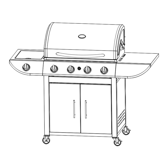
GAS GRILL ASSEMBLY, USE AND CARE MANUAL GD4819S
FOR OUTDOOR
USE ONLY
Do not attempt to assemble and use this grill unless you read this entire manual thoroughly.
Keep it in a handy place as it has answers for questions that may occur in your future use.
NOTE: THIS APPLIANCE IS NOT INTENDED TO INSTALL IN OR ON RECREATIONAL
VEHICLES OR BOATS.
1
Advertisement
Table of Contents

Related Manuals for Vanward GD4819S

Summary of Contents for Vanward GD4819S
- Page 1 GAS GRILL ASSEMBLY, USE AND CARE MANUAL GD4819S FOR OUTDOOR USE ONLY Do not attempt to assemble and use this grill unless you read this entire manual thoroughly. Keep it in a handy place as it has answers for questions that may occur in your future use.
-
Page 2: Technical Data
! ! !WARNING! ! ! 1. Failure to follow all manufacturers’ instructions could result in serious body injury and/or property damage. 2. Some parts of this grill may have sharp edges—especially as mentioned in this manual! Wear suitable protective gloves if necessary. 3. - Page 3 1.Patns List CODE PART Hood (Pre-Assembled to Body) Burner ooking grid Warming rack HOOD&BODY Grease Drip tray Side valve/Hose Assembly burner Flame Tamer iron plate side shelf Knob Side shelf Knob bezel Side burner SHELF SIDE shelf side burner Side burner grid Hook Right side trolley Assembly Side panel...
- Page 4 2. Parts Diagram...
-
Page 5: Assembly Instructions
3.Hardware Reference Diagram ASSEMBLY INSTRUCTIONS PLEASE READ THE INSTRUCTIONS CAREFULLY AND FOLLOW STEP BY STEP. THE GRILL SHOULD BE INSTALLED BY TWO PERSON. TOOLS REQUIRED: Head screwdriver & wrench (not provided). - Page 6 Step1: Attach the Trolley Base (C5) onto Right Side Trolley Assembly (C1) and Left Side Trolley Assembly (C10) using M6×12 Bolt & Ø6 Spring Washer (D1) as shown. Insert the two Lockable Castors (C4) and two standard Castors (C8) into the trolley frame assembly as shown.
- Page 7 Step3: Attach the Magnet (C6) onto bottom panel using M3×15 Bolt (D4). Attach the Door Axes (D2) to the trolley frame in the areas as shown. Step4: Attach the Upper Body Support (C11) onto the trolley frame assembly using M6×12 Bolt &...
- Page 8 Step5: Attach the Door Handles (C7) onto the Left Door (C9) and Right Door (C3) using M4×8 bolt & Ø4 spring washer as shown. M4*8 4 pcs Step6: Fit the doors to the cabinet by placing them into the door axes and then depressing the spring pins to insert into the upper body support.
- Page 9 Step7: Push the control knobs (B2) onto the valve stems on the control panel. Step8: Carefully place the Hood and Barbecue Body (A1) onto the trolley assembly. WARNING: DO NOT RELEASE THE BARBECUE BODY WHILE THE BARBECUE HAS NOT BEEN PROPERLY SEATED. THIS MAY RESULT IN INJURY OR DAMAGE TO YOUR BARBECUE.
- Page 10 Step9: Insert the Side Shelf (B1) into the two slots on the right side of the barbecue as shown. Step10: Tighten the pre-installed screws as the below picture shown.
- Page 11 Step11: Insert the side burner shelf (B5) into two slots of the barbecue as shown. Step12: Tighten the pre-installed screws as the below picture shown.
- Page 12 Step13: Secure the Side Burner Valve / Hose Assembly (A7) to the underside of the side burner shelf, using M4x8 Bolt & Ø4 Spring Washer (D5), whilst also fixing the Side Shelf Knob Bezel (B3) to the front of the side burner shelf, as shown. Assemble the side burner Knob (B2) onto the side burner valve.
- Page 13 Step15: Place the Side Burner Grid (B6) onto the side burner shelf. Step16: Carefully lay the Flame Tamer (A8) into the barbecue body ensuring it lies level within the body.
- Page 14 Step17: Put cast iron plate(A9) above burner without flame tamer(A3) as below pictures. Step18: Install the Warming Rack (A ) into the holes of lid and chassis...
- Page 15 Step19: Insert the Drip Tray (A6) by sliding it underneath the barbecue body. Insert the Grease Cup (A5) into the holder at the underside of the Drip Tray (A6), as shown. Step20: Place Grease cup (A ) onto the oil cup support under grease tray as below picture.
-
Page 16: Gas Connection
Step21: Hang the lighting rod (C13) onto the hook, either on the right or left side shelf, as shown. GAS CONNECTION ONLY USE THE HOSE ASSEMBLY SPECIFIED BY MANUFACTURER ON THIS GRILL. REPLACEMENT HOSE ASSEMBLIES MUST BE THOSE SPECIFIED BY THE MANUFACTURER. -
Page 17: Very Important
The precautions to be taken in the case of blockage of the Venturi or Venturis. 1. Do not block Venturi or Venturis! 2. Check and make sure there is no insect net in the Venturi or Venturis before using the BBQ, especially for long time no use. - Page 18 c. THE INLET OF THE PRESSURE REGULATOR SHALL BE FITTED TO CONNECT THE TYPE I CONNECTION OF THE TANK VALVE. 1. Make sure tank valve is in its full off position (turn clockwise to stop). 2. Check tank valve to assure it has proper external male threads. 3.
-
Page 19: Leak Testing
4. Install the protective cap back gas tank valve. LEAK TESTING Although all gas connections on the grill are leak tested at the factory prior to shipment, a complete gas tightness check must be performed at the installation site due to possible mishandling in shipment, or excessive pressure unknowingly being applied to the unit. -
Page 20: Installer Final Checklist
LEAK TEST BEFORE CONTINUING. 5. DO NOT REMOVE THE GREASE TRAY IF THE GRILL HASN’T COMPLETELY COOLED. 6. CLOSE ALL CONTROL KNOBS AND THE TANK VALVE WHEN THE GRILL IS NOT IN USE. 7. NEVER MOVE THE GRILL WHILE IN USE OR STILL HOT. 8. - Page 21 TO LIGHT MAIN AND SIDE BURNERS OF THE GRILL: 1. Read instructions before lighting. 2. Turn all knobs to “O” then open the tank valve. Always keep your face and body as far from the grill as possible when lighting. 3.
-
Page 22: Flame Characteristics
Keep a spray bottle of soapy water near the gas supply valve and check the connections before each use. Do not light the grill if odor of gas is present. FLAME CHARACTERISTICS Check for proper burner flame characteristics. Each burner is adjusted prior to shipment; however, variations in the local gas supply may take subtle necessary adjustments. - Page 23 7. NEVER light the burner with lid closed. Non-ignited gas accumulated inside a closed grill may cause explosions. 8. Check the burner flames periodically. 9. Turn off the gas supply when the grill is not in use. 10. Always turn off the gas tank completely and detach from the grill before moving.
-
Page 24: General Use Of The Grill
GENERAL USE OF THE GRILL: The grill burners encompass the entire cooking area and are side ported to minimize blockage from falling grease and debris. Above main burners are stainless steel radiated. The igniter knobs are located on the valve panel. Follow the lighting instructions printed on the control panel. - Page 25 abnormal status found. 3. Call our after service center warranty replacement parts. CLEANING ENAMELING CLEANING Always use the mildest cleaning the enameling parts. DO NOT USE ACID DETERGENT AND/OR ANTIRUST TO CLEAN THE CONTROL PANEL WITH PRINTING. SUCH STRONG CLEANSER MAY CLEAN OFF THE PRINTING.
-
Page 26: Troubleshooting
bottom of grease tray to absorb the grease. TROUBLE SHOOTING SPIDER AND INSECT WARNING Spiders and insects can nest in the burners after storing, these nest can cause fires inside the tube or beneath the grill. This is very dangerous condition. So always clean the burners before use after storing. - Page 27 Trouble Shooting PROBLEMS POSSIBLE CAUSE SOLUTIONS Electrode deposited with Use clean swab and alcohol to cooking residues clean. Electrode damaged Replace. Burner won’t light Electrode wires are loose or fall Reconnect or replace with new after turn and push Electrode assembly with wires. the knobs Orifice blocked Check the orifice for blockage.
-
Page 28: Grilling Tips
GRILLING TIPS 1. The doneness of meat, whether rare, medium, or well done, is affected by the thickness to a large extent. 2. The cooking time is affected by the kind of meat, the size and shape of the cut, the temperature of the meat when cooking begins, and the degree of doneness desired.
Need help?
Do you have a question about the GD4819S and is the answer not in the manual?
Questions and answers