Advertisement
Quick Links
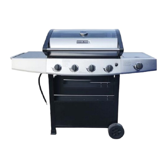
MODEL : # GD4838S-G
Distributor's: Vanston Inc.
WARNING
Improper installation,
adjustment, alteration, service
or maintenance can cause
injury or property damage.
Read this instruction
thoroughly before installing or
servicing this equipment.
WARNING
1. Do not store or use
gasoline or other
flammable
vapors
liquids in the vicinity of
this or any other appliance.
2 . An LP tank not connected
for use should not be
stored in the vicinity of
this
or
any
appliance.
DANGER
If you smell gas:
1.
Shut off gas to the
appliance.
2.
Extinguish any open flames.
3. Open the lid.
4. If the odor continues,keep
away from the appliance and
immediately call your gas
supplier or fire department.
WARNING
For Outdoor Use Only
manual
and
other
1
Advertisement

Related Manuals for Vanward GD4838S-G

Summary of Contents for Vanward GD4838S-G
- Page 1 MODEL : # GD4838S-G Distributor’s: Vanston Inc. WARNING Improper installation, adjustment, alteration, service or maintenance can cause injury or property damage. Read this instruction manual thoroughly before installing or servicing this equipment. WARNING 1. Do not store or use gasoline or other...
-
Page 2: Table Of Contents
TABLE OF CONTENTS Safety Information Package Contents Hardware Contents Preparation Assembly Instructions Installation Instructions Operating Instructions Care and Maintenance Troubleshooting Warranty... -
Page 3: Safety Information
SAFETY INFORMATION Please read and understand this entire manual before attempting to assemble, operate or install the product. If you have any questions regarding the product, please call customer service at 1-800-963-0211, 8 a.m-6 p.m., EST, Monday-Thursday, 8 a.m.-5 p.m., EST, Friday. ... - Page 4 SAFETY INFORMATION DANGER: If the information in above is not followed exactly, a fire causing death or serious injury may occur. The outdoor cooking gas appliance must be isolated from the gas supply piping system by closing its individual manual shutoff valve during any pressure testing of the gas supply system at test pressures equal to or less than 1/2 PSI (3.5 KPa).
-
Page 5: Package Contents
Package Contents... - Page 6 Package Contents Part Part Right Side Burner Bottom Panel Table Knob Bezel Left Leg Assembly Knob Right Leg Assembly Side Burner Front Panel Stay Rod for Side Burner holder condiment tray Side Burner Grid Condiment Tray Heat Tent Drip tray bracket right Cooking Grate Drip tray bracket left Warming Rack...
-
Page 7: Hardware Contents
Hardware Contents PREPARATION Before beginning assembly of product, make sure all parts are present. Compare parts with package contents list and hardware contents list. If any part is missing or damaged, do not attempt to assemble the product. Tools required for assembly (not included): Phillips Screwdriver, Wrench. - Page 8 1. Attach the four legs to bottom panel Using 2-M6x12 screws, secure left leg assembly (part 2) to bottom panel (part 1) and right leg assembly (part 3) with corresponding screws, Insert the stay rod for. condiment tray (part 5) into the mounting holes on left leg assembly and right leg assembly.
- Page 9 3. Install the Condiment Tray Insert 4 M6X12 screws with 4 M6 lock washers into the pre drilled holes in the upper portion of the front legs of the cart. Do not tighten screws. Line up the slotted holes in the condiment tray (part 6) to the screws.
- Page 10 5. Install left and right drip tray brackets Lock the drip tray bracket left (part 8) and drip tray bracket right (part 7) into the mounting hole at left and right leg assembly with corresponding M4x8 screws. 6. Install the cylinder stop rod and gas cylinder safety stop Place the cylinder stop rod (part 11) in the mounting hole at condiment tray and predrill hole in bottom panel.
- Page 11 7. Install the R pin at Cylinder stop rod and Gas Cylinder Safety Stop Lay cart on its side. Install three R pins in the pre drilled holes in the tips of the cylinder stop rod (part 11) and gas cylinder safety stop (part 12). Set cart upright. 8.
- Page 12 9. Install side table handle Unscrew the pre-installed screws on the handle, then put the screws through the holes on the side of side table, connect them to the handle (part 28), and tighten the screws (2). 10. Install the left side table Line up the holes in the left side table (part 14) with the pre-installed screws on left side of the firebox and hood assembly.
- Page 13 11. Install the right side burner table Line up the holes in the right side table (part 15) with the pre-installed screws on right side of firebox and hood assembly. Slide right side table into place over the screws. Tighten the pre-installed screws to secure the side table. 12.
- Page 14 13. Install side burner Place side burner through the hole in the top of the right side table. Insert the open end of side burner (part 18) over the outlet end of side burner valve (see illustration below). Center the hole in the side burner over the outlet on the control valve (it is ok that the open part of the side burner is not sealed).
- Page 15 15. Install the side burner grate Insert side burner grate (part 20) over the side burner making sure the tabs line up with corresponding holes (see illustration below). 16. Install heat tents Place the 4 heat tents (part 21) over each burner inside the firebox. Vented end of heat tent is placed toward the back of the firebox (see illustration below).
- Page 16 17. Install the cooking grate Place the cast iron cooking grates (part 22) into the firebox. Grates are porcelain coated. Seasoning is not required. 18. Install the warming rack Insert warming rack (part 23) making sure the tabs on the warming rack fit into the pre-drilled holes in the firebox (see illustration below).
- Page 17 19. Install the drip tray and grease cup Insert the drip tray (part 24) into the drip tray brackets from the back of the grill. Insert the grease cup (part 25) into the brackets on drip tray (see illustration below). 20.
- Page 18 21. Install matchstick holder assy. and igniter battery Locate screw at the 2/3 position of back left leg of cart. Do not tighten screw. Hang the single loop end of matchstick holder (part 27) onto the screw. You may also hang the top loop on the other end of the matchstick holder over the same screw (see illustration below).
- Page 19 INCORRECT REGULATOR ASSEMBLY The regulator and hose should not be routed through the gap between the bottom of firebox and the top of cart. Incorrect assembly will result in loss of warranty. Incorrect assembly may cause gas leakage, fire and severe bodily harm. The regulator and hose assembly must be routed through the hole of the left side panel into the cart.
- Page 20 WARNING: The Type I connective coupling (see Fig.24) supplied with your grill must not be replaced with a different type of grill/tank connection system. Removal will result in loss of warranty, gas leakage, fire and severe bodily harm. Thermally Sensitive Nut Hand Wheel External Propane...
- Page 21 b. Hand Disassembly: Make certain the tank valve and all the appliance valves are in the “OFF” position. 2. Turn the large plastic nut counter-clockwise until it is disassembled. 3. HAND LOOSEN ONLY. c. Excess Flow Control The propane regulator assembly incorporates an excess flow device designed to supply the grill with sufficient gas flow under normal conditions yet control excess gas flow.
- Page 22 LP GAS System Contact your gas supplier for a special regulator for bulk gas that fuels other appliances. Gas Consumption Total gas consumption of this grill with the burner(s) on “MAX” Table 1 below. Table 1 Burner Type BTU/HR Main Burners 12,000 Side Burner 12,000...
-
Page 23: Assembly Instructions
Grill Lighting Instructions To Light the Main Burners 1 .Make sure the control knobs are in the “OFF” position. 2 .Open the grill hood. 3 .Check the ignition pin position and distance between the pin and the burner. Refer to Step of the Assembly Instructions. - Page 24 Checking the Flame Refer to Fig.26 below (side view of grill) for where to check the flame after the grill is lit. Make sure you have a stable, mostly blue flame. Fig.26 Air Shutter Adjustment The gas burner shutters are adjusted at the factory for your convenience. The settings are: (a) 1/4 in.
- Page 25 Match Lighting Instructions IMPORTANT: The hood must be open when match lighting any burner. 1. Turn on gas supply a. If portable, at the LP cylinder valve. b. If permanent gas supply, at the manual gas shutoff valve. 2. Locate the flame observation holes on each side. 3.
- Page 26 Preheating Grill It is extremely important that your grill be up to temperature before you begin using it. After lighting, close the hood and preheat the grill on “MAX” for 15 minutes. This preheating will ensure that the cooking grate is hot enough for proper grilling. CAUTION: Do not cover the cooking grate during the preheating period.
- Page 27 WARNING: Please remember this is an outdoor gas grill. Many areas of the grill generate extreme heat. We have taken every precaution to protect you from the contact areas. However, it is impossible to isolate all high-temperature areas. Therefore, use good judgment and a certain degree of caution when grilling on this product.
- Page 28 LP tank should be securely locked by the gas cylinder safety stop at all times. An unlocked tank may fall or tilt which can cause injury or property damage. It is recommended to lock the tank all the time. Refer to Fig. 27 and Fig. 28. After positioning the tank in the opening, lift up the gas cylinder safety stop to lock the tank.
- Page 29 WARNING: When not connected to your grill, the LP gas tank must be stored in an upright position in a cool, shady, well-ventilated, outdoor location away from your grill or any other heat source. Failure to follow this warning could lead to tank valve damage, fire hazard and personal injury. Refilling a Propane Tank It is extremely important that your LP tank be filled properly when you take it to be refilled.
- Page 30 Specks of grease can gather on the surface of the stainless steel and get baked-on. These can usually be removed with warm soapy water or a stainless steel cleaner. As a last resort a mild abrasive pad could be used with a stainless cleaner. Use light pressure on the pad and always scrub in the direction of the grain.
-
Page 31: Care And Maintenance
Helpful Care and Maintenance Hints Before grilling, pre-heat grill for 15 minutes on “MAX” with hood down. To avoid uncontrolled flare-ups or grease fires, grill meats with hood open. Close hood if meats are thick or weather is cold, or if you are using a rotisserie or indirect cooking. - Page 32 Many solutions given here can make your grilling experience safer and more enjoyable. You can also call customer service department at 1-800-963-0211, 8 a.m. - 6 p.m., EST, Monday-Thursday, 8 a.m.- 5 p.m., EST, Friday. Problem Possible Cause Corrective Action 1.
- Page 33 Problem Possible Cause Corrective Action 1. Refill the LP Tank. LP tank is empty. Excessive flare-up. 2. Install the burner correctly. Burner is not aligned with the control valve. 3. Check the gas supply hose Gas supply is not sufficient. and make sure there are no leaks and no knots.
-
Page 34: Warranty
This warranty gives you specific legal rights, and you may also have other rights that vary from state to state. Manufacturer’s: Zhongshan Vanward Electric Appliance CO., LTD. Master Contract: 230994...
Need help?
Do you have a question about the GD4838S-G and is the answer not in the manual?
Questions and answers