
Related Manuals for Samsung PG117


Summary of Contents for Samsung PG117
-
Page 1: Table Of Contents
SUPER GRILLE MICROWAVE OVEN PG117 (SILVER) SERVICE Manual MICROWAVE OVEN CONTENTS 1. Precaution 2. Specifications 3. Operating Instructions 4. Disassembly and Reassembly 5. Alignment and Adjustments 6. Troubleshooting 7. Exploded Views and Parts List 8. PCB Diagrams 9. Schematic Diagrams... - Page 2 PRECAUTIONS TO BE OBSERVED BEFORE AND DURING SERVICING TO AVOID POSSIBLE EXPOSURE TO EXCESSIVE MICROWAVE ENERGY (a) Do not operate or allow the oven to be (c) Before turning on microwave power operated with the door open. for any service test or inspection within (b) Make the following safety checks on the microwave generating all ovens to be serviced before activating...
-
Page 3: Precaution
1. Precaution Follow these special safety precautions. Although the microwave oven is completely safe during ordinary use, repair work can be extremely hazardous due to possible exposure to microwave radiation, as well as potentially lethal high voltages and currents. 1-1 Safety precautions ( 1. - Page 4 1-2 Special Servicing Precautions (Continued) 17. When checking the continuity of the witches or transformer, always make sure that the power is OFF, and one of the lead wires is disconnected. 18. Components that are critical for safety are indicated in the circuit diagram by shading, or .
-
Page 5: Specifications
2. Specifications 2-1 Table of Specifications TIMER MICROWAVE : 99 MINUTES 90 SECONDS GRILL : 60 MINUTES POWER SOURCE 220V 50Hz, AC POWER CONSUMPTION MICROWAVE : 1,400W SUPER GRILL : 1,850W OUTPUT POWER FROM 180 TO 900W (IEC-705 TEST PROCEDURE) OPERATING FREQUENCY 2,450MHz MAGNETRON... -
Page 6: Operating Instructions
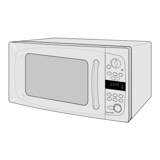
3. Operating Instructions 3-1 Control Panel 3-2 Features HEATER CONTROL PANEL HANDLE GLASS TRAY COUPLER DOOR GUIDE ROLLER DOOR LATCHES - 4 -... -
Page 7: Disassembly And Reassembly
4. Disassembly and Reassembly 4-1 Replacement of Magnetron, Fan Motor Assembly Remove the magnetron including the shield case, permanent magnet, choke coils and capacitors (all of which are contained in one assembly). 1. Disconnect all lead wires from the magnetron and lamp. 2. -
Page 8: Replacement Of Door Assembly
4-3 Replacement of Door Assembly 4-3-1 Removal of Door Assembly Remove hex bolts securing the upper hinge and lower hinge. Then remove the door assembly. 4-3-2 Removal of Door "C" Insert flat screwdriver into the gap between Door "A" and Door "C" to remove Door "C". Be careful when handling Door "C"... -
Page 9: Replacement Of Fuse
4-3-4 Reassembly of Test After replacement of the defective component parts of the door, reassemble it and follow the instructions below for proper installation and adjustment so as to prevent an excessive microwave leakage. 1. When mounting the door to the oven, be sure to adjust the door parallel to the bottom line of the oven face plate by moving the upper hinge and lower hinge in the direction necessary for proper alignment. -
Page 10: Replacement Of Control Circuit Board
4-8 Replacement of Control Circuit Board 4-8-1 Removal of Grille 1. Remove screws securing the Grille. 2. Push to the arrow direction and pull forward to take out. Grille screws 4-8-2 Removal of Control Box 1. Be sure to ground any static electric charge in your body and never touch the control circuit. -
Page 11: Alignment And Adjustments
5. Alignment and Adjustments PRECAUTION 1. High voltage is present at the high voltage terminals during any cook cycle. 2. It is neither necessary nor advisable to attempt measurement of the high voltage. 3. Before touching any oven components or wiring, always unplug the oven from its power source and discharge the high voltage capacitor. -
Page 12: High Voltage Capacitor
5-4 High Voltage Capacitor 1. Check continuity of the capacitor with the meter set at the highest resistance scale. 2. Once the capacitor is charged, a normal capacitor shows continuity for a short time, and then indicates 10M Ω . 3. -
Page 13: Output Power Of Magnetron
5-8 Output Power of Magnetron CAUTION MICROWAVE RADIATION PERSONNEL SHOULD NOT ALLOW EXPOSURE TO MICROWAVE RADIATION FROM MICROWAVE GENERATOR OR OTHER PARTS CONDUCTING MICROWAVE ENERGY. The output power of the magnetron can be measured by performing a water temperature rise test. Equipment needed : * Two 1-liter cylindrical borosilicate glass vessel (Outside diameter 190 mm) * One glass thermometer with mercury column... -
Page 14: Procedure For Measurement Of Microwave Energy Leakage
5-10 Procedure for Measurement of Microwave Energy Leakage 1) Pour 275±15cc of 20±5° C(68±9° F) water in a beaker which is graduated to 600cc, and place the beaker in the center of the oven. 2) Start to operate the oven and measure the leakage by using a microwave energy survey meter. -
Page 15: Troubleshooting
6. Troubleshooting PRECAUTION 1. CHECK GROUNDING BEFORE CHECKING FOR TROUBLE. 2. BE CAREFUL OF THE HIGH VOLTAGE CIRCUIT. 3. DISCHARGE THE HIGH VOLTAGE CAPACITOR. 4. WHEN CHECKING THE CONTINUITY OF THE SWITCHES OR TRANSFORMER, DISCONNECT ONE LEAD WIRE FROM THESE PARTS AND THEN CHECK CONTINUITY WITHOUT THE POWER SOURCE ON. - Page 16 6-1 Electrical Malfunction (continued) SYMPTOM CAUSE CORRECTIONS Oven lamp and fan motor turn on 1. Misadjustment or loose wiring Adjust door and latch switches. of primary latch switch 2. Defective primary latch switch Oven can program but timer 1. Open or loose wiring of Adjust door and interlock does not start.
-
Page 17: Exploded Views And Parts List
7. Exploded Views and Parts List 7-1 Exploded Views M016 M001 M003 M074 M053 M096 M030 M054 M031 M095 M106 M113 M019 M015 M005 M017 M095 M029 M051 M049 M068 M004 M094 M036 M034 P109 B006 B018 B001 M023 M035 P063 B002 B011... -
Page 18: Main Parts List
COVER-CEILING TBMO,MICA SHEET,T0.3,W110, M053 DE97-00314A ASSY-GUIDE AIR MT1044WB,TCO 160/60,-,- M054 DE32-10013A SENSOR THERMISTOR PT-312-K2,-,-,-,-,-,- M058 DE65-20014A CABLE CLAMP -,-,-,NY-66,-,DA-6N M068 DE64-00676C GRILLE PG117-S/XEC,PC,-,-,-,-,SIL,SIDE M074 DE97-00298B ASSY-SWING MOTOR PG113U,SWING-HEATER,230 M075 DE66-00116A CAM-MOTOR TBMO,POM,-,-,-,-,-,-,TOAST/BAK M094 DE63-00048A GASKET-STOPPER CE2613N,SECC,T1.0,W53,L15 M095 DE47-00025B HEATER SHG-E3000A,-,-,850W,-,230V,60OHM,... - Page 19 SPRING-KEY MW1255,HSWR,PI0.6,-,D5.5,L19, D009 DE61-00371A HINGE-UPPER TBMO-EURO,SCP1,T2.0,-,-,-,-, D010 DE61-00372A HINGE-LOWER TBMO-EURO,SCP1,T2.0,-,-,-,-, D011 DE64-00690A KEY-DOOR TBMO-EURO,NYLON#66,-,-,BLK,-,SI D016 DE64-00673A DOOR-SUB TBMO-EURO,PBT,-,-,-,-,BLK,SIDE D019 DE64-00675C HANDLE PG117-S/XEC,PC,-,-,-,-,SIL,SIDE EA D023 DE64-00674A DOOR-COVER TBMO-EURO,PC,SILVER COATING,- D024 DE64-00769A SCREEN-DOOR(B) PG113R,TEMP-GLASS,T3.2,W3 D049 ASSY DOOR PG117-S/XEC,SIL,SIDE S.N.A - 17 -...
- Page 20 C015 C012 C003 C085 C084 C029 C041 C009 C019 C005 Code No. Description Specification Q'ty Remark C001 DE94-00842D ASSY CONTROL-PANEL -,PG117-S/XEC,SIL,SID C003 RC-TBMO2-01 ASSY PCB PARTS PG117R(TACT),220V50HZ C005 DE64-00677D CONTROL-PANEL PG117-S/XEC,PC,-,-,-,-,SIL C009 DE64-00689A WINDOW-DISPLAY TBMO-EURO,SAN,SIDE(TACT), C011 DE64-00681D BUTTON-SELECT(A) PG117-S/XEC,PC,-,-,SIL, C012...
-
Page 21: Standard Parts List
7-5 Standard Parts List Code No. Description Specification Q'ty Remark DE60-20063A BOLT-FLANGE M4,10,ZPC3,YEL,MSWR,-,-,-,- SLIDER-L DE60-20063A BOLT-FLANGE M4,10,ZPC3,YEL,MSWR,-,-,-,- SLIDER-R 6021-001130 NUT-CIRCULAR SPN-4,ID3.9,OD12,BLK,SK-5,H1.4,T0.3 6021-001130 NUT-CIRCULAR SPN-4,ID3.9,OD12,BLK,SK-5,H1.4,T0.3 DE60-30016A NUT-FLANGE M4,MSWR10,-,-,-,-,-,-,- HEATER DE60-30016A NUT-FLANGE M4,MSWR10,-,-,-,-,-,-,- THER DE60-10082H SCREW-A -,-,-,-,2S-4X12,TOOTHED,-,-,-,- B-PLATE DE60-10082H SCREW-A -,-,-,-,2S-4X12,TOOTHED,-,-,-,- B/LATCH-R DE60-10082H SCREW-A -,-,-,-,2S-4X12,TOOTHED,-,-,-,-... -
Page 22: Pcb Diagrams
8. P.C.B Diagrams 8-1 P.C.B Diagrams ( This Document can not be used without Samsung's authorization ) - 20 -... - Page 23 8-2 P.C.B Parts List Code No. Description Specification Q'ty Remark 3501-001062 RELAY-POWER 24VDC,523.2mW,16A,1FormA,15mS, RY03 3501-001068 RELAY-POWER 24Vdc,523mW,16A,1FormA,15mS,10 RY07,RY08 3501-001155 RELAY-MINIATURE 24VDC,200MW,3000MA,1FORMA,10MS,10MS RY01,RY02,RY04,RY05,RY06 3601-001126 FUSE-CARTRIDGE 250V,1.6A,FAST-ACTING,CERAMIC,5x20mm FUSE 3708-001551 CONNECTOR-FPC/FFC/PIC 14P,1.25mm,STRAIGHT,SN CN04 DE07-00037T LED DISPLAY CSE-4246G-18,TBMO(RUSSIA),-,40SEG, LED1 DE09-00054A IC MICOM TPM87CH47U,OTP-16K,QFP,-,-,- IC01 DE26-00078A TRANS-L.V SLV-C100,230V,50HZ,AC17.0V/6.8V,...
-
Page 24: Schematic Diagrams
9. Schematic Diagrams 9-1 Schematic Diagrams ( This Document can not be used without Samsung's authorization ) - Page 25 ELECTRONICS This Service Manual is a property of Samsung Electronics Co.,Ltd. © Samsung Electronics Co., Ltd. June 2003 Any unauthorized use of Manual can be punished under applicable Printed in Korea International and/or domestic law Code No. : DE68-03202A...
Need help?
Do you have a question about the PG117 and is the answer not in the manual?
Questions and answers