Table of Contents
Advertisement
Quick Links
Advertisement
Table of Contents

Subscribe to Our Youtube Channel
Summary of Contents for S&P MD
- Page 1 QA/IOM/46 Issue 11 - MD Dehumidifier...
-
Page 2: Table Of Contents
Fan only / dehumidifying (modes of operation) 3.4. Fan speed operation 4. Installation wiring 5. Control panel 6. Maintenance and fault finding 6.1. Maintenance 6.2. Faults 6.3. Technical support 7. Spares list 7.1. Electrical 7.2. Refrigeration/ mechanical 8. Contact Information QA/IOM/46 Issue 11 - MD Dehumidifier... -
Page 3: General Description
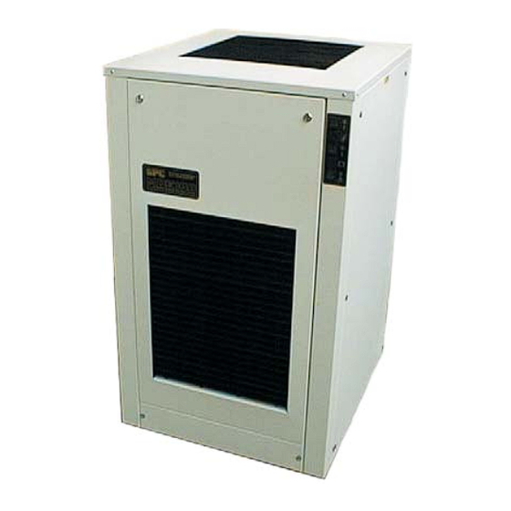
The collected condensate is then removed by an integral condensate pump. Figures 1. to 4. Show the general layout of the dehumidifiers externally and internally. Figure 1. General layout of MD units with front grille removed Figure 2. General layout of MD units Page 3... - Page 4 Figure 3. Front view with front panel removed Figure 4. Side view with side panel removed Page 4 QA/IOM/46 Issue 11 - MD Dehumidifier...
-
Page 5: General
To prevent the evaporator coil freezing below design range conditions, a low pressure cut-out is included in the refrigeration system. This detects if the condensate is freezing on the evaporator and stops the compressor. The coil is allowed to thaw passively before the compressor is restarted. Page 5 QA/IOM/46 Issue 11 - MD Dehumidifier... -
Page 6: Fan And Ventilation System
If the level of the condensate in the pump drain pan becomes excessively high, the warning light on the front panel lights up, Figure 10. If this occurs refer to section 6.2. Page 6 QA/IOM/46 Issue 11 - MD Dehumidifier... -
Page 7: Performance
1.5. Performance The MD range of Dehumidifiers has been designed to operate between the following conditions: Dry Bulb Temperature Relative Humidity (%) ( C) Lower Limit Upper Limit This corresponds to an approximate minimum wet bulb temperature of 13 C and maximum of 31 C. -
Page 8: Preparation Of Dehumidifier From Delivery
It is recommended that the unit, once positioned, is stood at rest for 24 hours prior to operation. Page 8 QA/IOM/46 Issue 11 - MD Dehumidifier... -
Page 9: General Operating Instructions
GENERAL OPERATING INSTRUCTIONS This section describes the practical operation of the MD range of dehumidifiers. 3.1. Siting of the dehumidifier The dehumidifiers should never be moved down slopes as they may become unstable and fall over. To move from one level to another they must be lifted by an appropriate lifting device operated by a competent person. -
Page 10: Changing From Pump To Gravity Condensate Discharge
Fan only mode may be chosen if the humidity level in the conditioned space has been lowered to the required level but it is still desirable to have air movement within the space to minimise stratification or air stagnation. Page 10 QA/IOM/46 Issue 11 - MD Dehumidifier... -
Page 11: Fan Speed Operation
The MD100 is suitable for running from a 13 Amp supply socket. Both the MD160 and MD200 should be hard-wired from a 20 Amp supply. Wiring diagrams for the MD100, MD160 andMD200 are shown in figures 7. to 9. Page 11 QA/IOM/46 Issue 11 - MD Dehumidifier... - Page 12 FIGURE 7. WIRING DIAGRAM FOR THE MD100 Page 12 QA/IOM/46 Issue 11 - MD Dehumidifier...
- Page 13 FIGURE 8. WIRING DIAGRAM FOR THE MD160 Page 13 QA/IOM/46 Issue 11 - MD Dehumidifier...
- Page 14 FIGURE 9. WIRING DIAGRAM FOR THE MD200 Page 14 QA/IOM/46 Issue 11 - MD Dehumidifier...
-
Page 15: Control Panel
The panels must never be removed when the mains power is connected. Turn the dehumidifier off and either remove the plug from the socket or isolate the supply when access is required. Page 15 QA/IOM/46 Issue 11 - MD Dehumidifier... -
Page 16: Faults
Condensate pump failure. This requires an engineer to investigate Drain pan overflows: Condensate high level switch failure Float switches are located within the pump drain pan and require an engineer to check their operation Page 16 QA/IOM/46 Issue 11 - MD Dehumidifier... -
Page 17: Technical Support
18A contactor On delay timer Switches Condensate pump Compressor start kit 7.2 Refrigeration / Mechanical Air filter Compressor Thermal expansion valve Liquid line drier Pressure switch Liquid receiver Evaporator coil Condenser coil Page 17 QA/IOM/46 Issue 11 - MD Dehumidifier... -
Page 18: Contact Information
S & P Coil Products Ltd SPC House, Evington Valley Road, Leicester, LE5 5LU Tel: (0116) 249 0044 Fax: (0116) 249 0033 e-mail: spc@spcoils.co.uk Web: www.spcoils.co.uk QA/IOM/46 Issue 11 - MD Dehumidifier...


Need help?
Do you have a question about the MD and is the answer not in the manual?
Questions and answers