Table of Contents
Advertisement
Quick Links
Advertisement
Table of Contents

Related Manuals for PreCise IX-101


Summary of Contents for PreCise IX-101
- Page 1 PreCise IX-101 Installation Guide...
-
Page 2: Table Of Contents
Appendix B – IX101 Electrical Installation ................12 Antenna Connections: ..................12 POWER Connections: ..................12 DIGITAL INPUTS: ....................12 IX-101 Specifications ......................... 13 GSM Radio ......................13 GPS ........................13 Power ......................... 14 ... -
Page 3: Introduction
Introduction The IX-101 is a rugged, reliable asset management device that combines a GPS receiver and a GSM/GPRS cellular radio for an easy-to-use and effective method to capture and transfer location and utilization data for various types of assets. The system provides out-of-the-box, Internet-based reporting along with an advanced data- export interface to integrate with existing asset management solutions. -
Page 4: Warnings & Cautions
Warnings & Cautions Read and follow all safety rules and instructions before installing or operating this equipment. Never operate a vehicle within a closed area. Always assure proper ventilation before starting engine. Always use eye protection. Use goggles that are ANSI approved against impacts and shattering. ... -
Page 5: Installation Instructions
Check the contents of the shipping package and verify the following items are included: Included Items item # Supply PreCise IX module power harness installation guide magnet-mount combination antenna – GPRS & GPS Recommended Supplies... -
Page 6: Mounting Locations
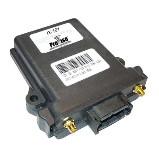
IX modules. The ICC ID is a 19 or 20-digit identifier located on the IX-101 module. The equipment identifier can be a combination of letters and/or numbers that you use to uniquely identify your equipment. Examples include the Vehicle Identification Number (VIN), the license plate number, or the driver’s... - Page 7 necessary connections to the antenna cables as well as the power harness. You should consider a few points prior to selecting a location: Consider the wire routing for the antenna and power. Consider protection of connections from weather and items stored nearby. ...
-
Page 8: Electrical Connections
Electrical Connections The IX modules are designed to operate from a continuous voltage source and a switched voltage source (ignition signal). To track and report total operating hours, as well as allow the unit to manage its own shut-down sequence, you must connect the green ignition wires properly. - Page 9 RED (PWR) Battery Positive (7-36VDC continuous) BLACK (GND) Battery Negative GREEN (IGN) * Ignition (7-36VDC while engine is running) GREEN (IGN) * Chassis Ground WHITE (IN1) WHITE (IN1) BLUE (IN2) BLUE (IN2) YELLOW (AUX_B) ORANGE (AUX_A) Figure 2: Connection Diagram Figure 3: Input Connections 415 N.
-
Page 10: Post-Install Checklist
Confirm the device is reporting either by watching for the Cellular LED to turn solid green (not blinking), or by checking the asset’s status on the PreCise website (www.preciseinfox.com) o NOTE: This step assumes that the asset has already been configured in the PreCise website. -
Page 11: Appendix A - Led/Pinout Definitions
Appendix A - LED/Pinout Definitions CELL LED GPS LED CELL Figure 4: Faceplate GPS & Time/Date Status LED SHORT RED BLINK: GPS receiver is not communicating. LONG RED BLINK: GPS antenna short- or open-circuit detected. SHORT GREEN BLINK: GPS is searching for current position. ... -
Page 12: Appendix B - Ix101 Electrical Installation
Appendix B – IX101 Electrical Installation Antenna Connections: Two antenna cables must be connected to the IX-101. The GPS cable is connected to the small gold (SMA) connector in the right side of the front panel. The GSM/GPRS phone antenna cable with the second small (SMA) connector must be connected to the small gold connector in the left side of the front panel. -
Page 13: Ix-101 Specifications
IX-101 Specifications GSM Radio Parameter Rating Units Frequency bands EGSM850 transmit 824-849 EGSM850 receive 869-894 EGSM900 transmit 880-915 EGSM900 receive 925-960 GSM1800 transmit 1710-1785 GSM1800 receive 1805-1880 GSM1900 transmit 1850-1910 GSM1900 receive 1930-1990 Output power EGSM850 +33 ±2 dBm (max) EGSM900 +33 ±2... -
Page 14: Power
Power Parameter Rating Units Supply voltage Operating 9.8 to 32.0 Continuous 65.0 V (max) Over-voltage protection threshold (Note 1) 40 V (min) V (max) Input current (average) Vin=24V dc Sleep mA (typ) Operating mA (typ) Vin=12V dc Sleep mA (typ) Operating mA (typ) 1. -
Page 15: Manufacturer Limited Warranty And Limitation Of Liability
MANUFACTURER LIMITED WARRANTY AND LIMITATION OF LIABILITY Manufacturer warrants that on the Date of Purchase this Product will conform to Manufacturer's published specifications for the product, which are available from Manufacturer on request, and Manufacturer warrants that the product is free from defects in materials and workmanship. This Limited Warranty extends for twelve (12) months from the date of manufacture. - Page 16 Part 15 Notice: This device complies with Part 15 of the FCC rules. Operation is subject to the following two conditions: (1) This device may not cause harmful interference, and (2) this device must accept any interference received, including interference that may cause undesired operation. NOTES: 415 N.
Need help?
Do you have a question about the IX-101 and is the answer not in the manual?
Questions and answers