Table of Contents
Advertisement
Quick Links
User's Manual
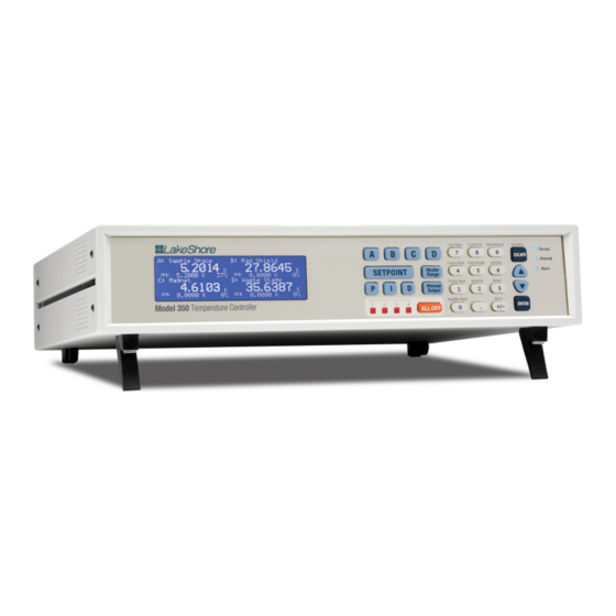
Model 350
Temperature Controller
Lake Shore Cryotronics, Inc.
sales@lakeshore.com
575 McCorkle Blvd.
service@lakeshore.com
Fax: (614) 891-1392
Westerville, Ohio 43082-8888 USA
www.lakeshore.com
Telephone: (614) 891-2243
Methods and apparatus disclosed and described herein have been developed solely on company funds of Lake Shore
Cryotronics, Inc. No government or other contractual support or relationship whatsoever has existed which in any
way affects or mitigates proprietary rights of Lake Shore Cryotronics, Inc. in these developments. Methods and appa-
ratus disclosed herein may be subject to U.S. Patents existing or applied for.
Lake Shore Cryotronics, Inc. reserves the right to add, improve, modify, or withdraw functions, design modifications,
or products at any time without notice. Lake Shore shall not be liable for errors contained herein or for incidental or
consequential damages in connection with furnishing, performance, or use of this material.
Rev. 1.3
P/N 119-057
09 January 2014
|
www.lakeshore.com
Advertisement
Chapters
Table of Contents
Troubleshooting

Related Manuals for Lake Shore 350


Summary of Contents for Lake Shore 350
- Page 1 Lake Shore Cryotronics, Inc. reserves the right to add, improve, modify, or withdraw functions, design modifications, or products at any time without notice. Lake Shore shall not be liable for errors contained herein or for incidental or consequential damages in connection with furnishing, performance, or use of this material.
- Page 2 (b) the Product is fit for any particular purpose expressly or by an authorized Lake Shore employee, sales representative, dealer or impliedly made known to Lake Shore at the time of the conclusion of an authorized Lake Shore original equipment manufacturer (OEM).
- Page 3 WinZip™ is a registered trademark of Nico Mak of Connecticut Copyright 2012-14 Lake Shore Cryotronics, Inc. All rights reserved. No portion of this manual may be reproduced, stored in a retrieval system, or transmitted, in any form or by any means, electronic, mechanical, photocopying, recording, or otherwise, without the express written permission of Lake Shore.
- Page 4 Model 350 Temperature Controller...
- Page 5 To qualify for the CE Mark, the Model 350 meets or exceeds the requirements of the European EMC Directive 89/336/EEC as a CLASS A product. A Class A product is allowed to radiate more RF than a Class B product and must include the follow- ing warning: WARNING:This is a Class A product.
-
Page 7: Table Of Contents
2.4 Model 350 Theory of Operation ........ - Page 8 2.14.2 Tuning Proportional ............40 Model 350 Temperature Controller...
- Page 9 3.6.5.3 Connecting to the Model 350 ........
- Page 10 5.5.2 Warm Up Control ............. 90 Model 350 Temperature Controller...
- Page 11 5.6 Monitor Out ................90 5.6.1 Monitor Units .
- Page 12 8.2.3 Intermittent Lockups ............165 Model 350 Temperature Controller...
- Page 13 8.14.1 Contacting Lake Shore ........
- Page 14 Model 350 Temperature Controller...
-
Page 15: Product Description
Lake Shore’s industry-leading Cernox™ sensors provides a cryogenic solution that’s demonstrably best-in-class. The patented noise reduction input circuitry of the Model 350 is just one reason why this controller works so well for ultra-low temperature (ULT) applications, all the way down to 100 mK. -
Page 16: Application Versatility
1: Introduction HAPTER In short, the Model 350 cryogenic temperature controller brings a new level of power, precision, and performance to critical low temperature physics research. It is ideal for use with He-3 systems, adiabatic demagnetization refrigerators (ADRs), certain dilu- tion refrigerators, and many other applications demanding low thermal power and high measurement precision. -
Page 17: Precision Temperature Control
Relays can be assigned to any alarm or operated manually. Choosing appropriate PID control settings for a closed loop sys- tem can be tedious, but the Model 350 provides the temperature control loop auto- tuning feature to simplify the process. It’s an automated process that measures system characteristics and computes setting values for P, I, and D for you. -
Page 18: Measurement Isolation
1: Introduction HAPTER 1.4.3 Measurement Optocouplers isolate the analog front end of the Model 350 from digital circuitry and the instrument chassis. Optical isolation minimizes the effect of digital noise on the Isolation measurement and breaks ground loops. 1.4.4 Configurable The Model 350 offers a bright, graphic liquid crystal display with an LED backlight that simultaneously displays up to eight readings. - Page 19 1.5 Sensor Selection Model Useful range Magnetic field use Negative Cernox™ CX-1010 0.1 K to 325 K T > 2 K & B " 19 T Temperature Cernox™ CX-1030-HT 0.3 K to 420 K T > 2 K & B " 19 T Coefficient RTDs Cernox™...
- Page 20 Typical sensor sensitivities were taken from representative calibrations for the sensor listed Control stability of the electronics only, in an ideal thermal system Non-HT version maximum temperature: 325 K Accuracy specification does not include errors from room temperature compensation TABLE 1-2 Typical sensor performance Model 350 Temperature Controller...
-
Page 21: Model 350 Specifications
1.6 Model 350 Specifications 1.6 Model 350 Specifications 1.6.1 Input Specifications Sensor Input Range Excitation Current Display Measurement Electronic Measurement Temperature Electronic Temperature Resolution Resolution Accuracy Coefficient Stability Coefficient (at 25 °C) NTC RTD/ Negative/ 0 ) to 10 ) 1 mA 0.1 m) -
Page 22: Sensor Input Configuration
Improves accuracy of DT-470 diode to ±0.25 K from 30 K to 375 K; improves SoftCal™ accuracy of platinum RTDs to ±0.25 K from 70 K to 325 K; stored as user curves Math Maximum and minimum Filter Averages 2 to 64 input readings Excitation frequency 10 Hz squarewave Model 350 Temperature Controller... -
Page 23: Control
1.6.4 Control 1.6.4 Control There are 4 control outputs. 1.6.4.1 Heater Outputs (Outputs 1 and 2) Control type Closed loop digital PID with manual heater output or open loop Update rate 10/s Tuning Autotune (one loop at a time), PID, PID zones Control stability Sensor dependent, see Input Specifications table PID control settings... -
Page 24: Analog Outputs (Outputs 3 And 4)
Heater output resolution 0.01% Display annunciators Control input, alarm, tuning LED annunciators Remote, Ethernet status, alarm, control outputs Keypad 27-key silicone elastomer keypad Front panel features Front panel curve entry, display contrast control, and keypad lock-out Model 350 Temperature Controller... -
Page 25: Interface
Capabilities SH1, AH1, T5, L4, SR1, RL1, PP0, DC1, DT0, C0, E1 Reading rate To 10 rdg/s on each input Software support LabVIEW™ driver (contact Lake Shore for availability) Function Emulates a standard RS-232 serial port Baud Rate 57,600 Connector... -
Page 26: Safety Summary And Symbols
Lake Shore Cryotronics, Inc. assumes no liability for Cus- tomer failure to comply with these requirements. The Model 350 protects the operator and surrounding area from electric shock or burn, mechanical hazards, excessive temperature, and spread of fire from the instru- ment. - Page 27 1.7 Safety Summary and Symbols Equipment protected throughout Direct current (power line) by double insulation or reinforces insulation (equivalent to Class II of Alternating current (power line) IEC 536—see Annex H) Alternating or direct current (power line) CAUTION: High voltages; danger of electric shock;...
- Page 28 1: Introduction HAPTER Model 350 Temperature Controller...
-
Page 29: General
Terminology below 1 K. This is an attempt to demonstrate how the Model 350 can be integrated into these systems for resistance measurement, temperature measurement and tem- perature control. It is hoped that from these examples, those knowledgeable in cryo- genic techniques will become familiar with the terminology used throughout this manual and the intended operation of many of the instrument features. - Page 30 He. The still requires a few milliwatts of heat from a resistive heater to sustain evaporation. The still output can drive the still heater. This is a good location for a diagnostic temperature sensor. Model 350 Temperature Controller...
-
Page 31: 3He Cryostat
2.3.2 3He Cryostat Heat exchangers: one or more heat exchangers serve to cool returning He rich liquid to near the temperature of the mixing chamber. Also used to heat sink mea- surement leads. Mixing chamber: chamber where cooling action takes place. Holds both He rich liquid and dilute He separated by a phase boundary. -
Page 32: Model 350 Theory Of Operation
Current can also be scaled easily, which is necessary to achieve low exci- tation. The Model 350 has 11 current settings from 1 mA down to 10 nA. These cur- rents have low noise and almost no DC component to self-heat the sensor. -
Page 33: Excitation Modes
2.4.3 Resistance The Model 350 has full-scale resistance ranges from 10 ) to 300 k). Most ranges are available with either a 10 mV or 1 mV excitation. The goal is to use enough excitation... -
Page 34: Shielding And Grounding Theory
Most parts of a good strategy are obvious, some are not and even the best plans do not work all the time. The Model 350 offers several features that help control noise and maintain signal integrity. Specific recommendations on installation and lead wiring are given in Chapter 3. -
Page 35: Active Common Mode Reduction
(voltages are present between measurement leads). 2.4.5 Measurement The Model 350 has a built in hardware low-pass filter with a -3dB frequency of 16 Hz. Additional filtering is done in the instrument firmware as a linear average. Speed and Filtering The input hardware settles about 100 milliseconds after a temperature (sensor resis- tance) change if no range change is required. -
Page 36: Ground Loop Noise
2.5.4 Digital Circuit All digitally controlled instruments emit some high-frequency noise both through the air and on their leads. Emission from a Model 350 is very low and will not affect sen- Noise sor measurements if the instrument is installed properly. The high frequency noise can interfere with very sensitive measurements being made in the same Dewar. -
Page 37: Resistor Thermal Noise
Error 2.6.1 Warm Up and When the Model 350 is first turned on, it should be allowed to warm up for at least 30 mins before use to allow its internal temperature to stabilize. Warm up is an exag- Temperature Drift gerated form of temperature drift because the temperature change inside the enclo- sure is larger and faster than would be experienced in a laboratory setting. -
Page 38: Lead Resistance
To measure the effect of self-heating use the current ranges available in the Model 350. Begin by cooling the sensor to the desired temperature and measure its value using the highest current excitation available for the sensor being measured. Step up one resistance range (dropping the current by about 2/3) and measure the sensor resistance again. -
Page 39: Considerations When Measuring Ultra-Low Temperatures Below 300 Mk
The sensor calibration uncertainty is usually listed on the sensor’s data sheet. For the CX-1010 at 100 mK, the uncertainty is ±4 mK. Contact Lake Shore for more informa- tion concerning the uncertainties surrounding calibration, drift, and other sources of error that determine the uncertainties associated with the sensor. - Page 40 30 nA, but if the excitation is further reduced to 10 nA the total uncertainty increases due to the contribution of the instrument accuracy. The RX-102B illustrates the tradeoff even clearer; the total uncertainty almost doubles from 30 nA to 10 nA. Model 350 Temperature Controller...
- Page 41 2.7.3 Considerations When Measuring Ultra-Low Temperatures Below 300 mK ±100 ) 10 nA +0.02 (0.1%rng) ±8.1 +0.0 ±12.1 ±0.04%rdg 100 mK 3,546 –12,578 6 × 10 ±30 ) (0.1%rng) ±4 102B 30 nA +0.2 ±2.5 +0.2 ± 6.5 ±0.04%rdg ±10 ) (0.1%rng) 100 nA +2.1 ±0.9...
-
Page 42: Temperature Sensor Selection
Another thing to consider when choosing a temperature sensor is that instruments like the Model 350 are not able to read some sensors over their entire temperature range. Lake Shore sells calibrated sensors that operate down to 20 millikelvin (mK), but the Model 350 is limited to above 100 mK in its standard configuration. -
Page 43: Sensor Package
Both interpolation tables are opti- mized to allow accurate temperature conversion. The smaller table, called a break- point interpolation table, is sized to fit into instruments like the Model 350 where it is called a temperature response curve. -
Page 44: Softcal
Model 350 user curve loca- tions. You can also use it to read curves from the Model 350 and save them to files. Lake Shore calibrated sensors are provided with a CD containing all the proper for- mats to load curves using the Curve Handler™... -
Page 45: Mounting Materials
2.10.1 Mounting Materials 2.10.1 Mounting Choosing appropriate mounting materials is very important in a cryogenic environ- ment. The high vacuum used to insulate cryostats is one consideration. Materials Materials used in these applications should have a low vapor pressure so they do not evaporate or out-gas and spoil the vacuum insulation. -
Page 46: Lead Wire
Leads should be tinned before bonding to reduce the time that heat is applied to the sensor lead. Clean the solder flux after soldering to prevent corrosion or outgassing in vacuum. Model 350 Temperature Controller... -
Page 47: Thermal Anchoring Leads
To measure the effect of self-heating use the current ranges available in the Model 350. Begin by cooling the resistor to the desired temperature and measure its value using the highest current excitation available for the resistor being measured. -
Page 48: Heater Selection And Installation
2.11.1.2 Sample Heater: Output 2 The Model 350 can provide up to 1 W of power from Output 2. Output 2 is designed to provide small amounts of heat for fine control of a sample stage at very low tempera- tures. -
Page 49: Outputs 3 And 4
It is possible to choose a heater value that results in a maximum power greater than the power rating of 75 W for output 1, but doing so can cause the Model 350 to work improp- erly. In this situation the max user current setting should be used to limit the power. Refer to section 4.5.1.1.1 for details on using the max user current setting. -
Page 50: Heater Wiring
If both control stability and measurement accuracy are critical it may be necessary to use two sensors, one for each function. Many tempera- ture controllers including the Model 350 have multiple sensor inputs for this reason. 2.12.4 Thermal Mass Cryogenic designers understandably want to keep the thermal mass of the load as small as possible so the system can cool quickly and improve cycle time. -
Page 51: System
2.13 PID Control For closed-loop operation, the Model 350 temperature controller uses an algorithm called PID control. The control equation for the PID algorithm has three variable terms: proportional (P), integral (I), and derivative (D). See FIGURE 2-4. Changing these variables for best control of a system is called tuning. -
Page 52: Derivative (D)
I-setting when used. 2.13.4 Manual Output The Model 350 has a control setting that is not a normal part of a PID control loop. Manual Output can be used for open loop control, meaning feedback is ignored and the heater output stays at the user's manual setting. - Page 53 2.13.4 Manual Output FIGURE 2-4 Examples of PID control www.lakeshore.com...
-
Page 54: Manual Tuning
Lower heater ranges are normally needed for lower temperature. The Model 350 is of no use controlling at or below the temperature reached when the heater was off. Many systems can be tuned to control within a degree or two above that temperature. -
Page 55: Tuning Integral
2. Use the oscillation period of the load that was measured in section 2.14.2 in sec- onds. Divide 1000 by the oscillation period to get the integral setting. 3. Enter the integral setting into the Model 350 and watch the load temperature approach the setpoint. -
Page 56: Tuning Derivative
D. Autotune works only with one control loop at a time and does not set the man- ual output or heater range. Setting an inappropriate heater range is potentially dan- gerous to some loads, so the Model 350 does not automate that step of the tuning process. -
Page 57: Zone Tuning
Trying to remember when to use which set of tuning parameters can be difficult. The Model 350 has a Zone feature as one of its tuning modes that can help. - Page 58 2: Cooling System Design and Temperature Control HAPTER Model 350 Temperature Controller...
-
Page 59: General
Instruments themselves may be shipped as several parts. The items included with the Model 350 are listed below. Contact Lake Shore immediately if there is a shortage of parts or accessories. Lake Shore is not responsible for any miss- ing items if not notified within 60 days of shipment. -
Page 60: Line Input Assembly
TABLE 3-1 Line voltage AC line voltage is set at Lake Shore, but it is good to verify that the AC line voltage indica- tor in the fuse drawer window is appropriate before turning the instrument on. The instrument may be damaged if turned on with the wrong voltage selected. Also remove and verify that the proper fuse is installed before plugging in and turning on the instru- ment. -
Page 61: Power Cord
3.4.4 Power Switch The power switch is part of the line input assembly on the rear panel of the Model 350 and turns line power to the instrument on and off. When the circle is depressed, power is off. -
Page 62: Sensor Lead Cable
A shield is most effective when it is near the measurement potential so the Model 350 offers a shield at measurement common. The shield of the sensor cable should be connected to the shield pin of the input connector. The shields should not be connected to earth ground on the instrument chassis. -
Page 63: Two-Lead Sensor Measurement
3.5.5 Two-Lead Sensor Measurement Resistive sensor Diode (option only) – – – – FIGURE 3-4 4-lead measurement 3.5.5 Two-Lead Sensor There are times when crowding in a cryogenic system forces users to read sensors in a two-lead configuration because there are not enough feedthroughs or room for lead Measurement wires. -
Page 64: Sensor Polarity
Refer to section 7.4 for installation of the Model 3061. The Model 3061 adds a capacitance input to the Model 350, appearing on the display as input D. The card has separate voltage feedback and current excitation for the sen- sor. -
Page 65: Wiring, Guarding And Shielding
Test any system for sensor interference before it is permanently sealed. 3.5.9 Thermocouple The information in this section is for a Model 350 configured with thermocouple sen- sor inputs. Thermocouple inputs are not installed on the standard Model 350, but can Sensor Inputs be added by purchasing the Model 3060 dual thermocouple input option. -
Page 66: Thermocouple Installation
Specifications are detailed in section 1.6. For help on Setup choosing and installing an appropriate resistive heater, refer to section 2.11. 3.6.1 Heater Output This section describes Output 1 and Output 2. Description Model 350 Temperature Controller... -
Page 67: Output 1
This is a common jack, and additional mating connectors can be purchased from local electronic suppliers, or from Lake Shore as P/N 106-009. The heater is connected between the HI and LO terminals. -
Page 68: Heater Output Wiring
Also avoid connecting heater leads to sensor leads or any other instrument inputs or outputs. 3.6.4 Heater Output The heater output circuitry in the Model 350 is capable of sourcing 75 W of power. This type of circuitry can generate some electrical noise. The Model 350 was designed Noise... -
Page 69: Power Supply Setup
3.6.5 Powering Outputs 3 and 4 Using an External Power Supply Output Type: most available voltage programmable power supplies are configured for voltage output. This is different than Outputs 1 and 2 on the 350 which are configured for current output. The differences between the two are not signifi- cant when used in warm up mode. -
Page 70: Programming Voltages Under 10 V
R1 to R2: Vout = 10V x R1/(R1+R2). It is also important to keep the sum of R1 + R2 > 1000 ) or the Model 350 output may not reach the output voltage setting due to internal overload protection. For a programming input range of 0 V to 5 V, recom- mended values are: R1 = R2 = 2000 ). -
Page 71: General
4.1 General Chapter 4: Operation 4.1 General This chapter provides instructions for the general operating features of the Model 350 temperature controller. Advanced operation is in Chapter 5. Computer interface instructions are in Chapter 6. FIGURE 4-1 Model 350 front panel 4.1.1 Understanding... -
Page 72: Front Panel Description
(FIGURE 4-1). The Direct Operation keys provide one touch access to the most often used functions of the Model 350. The Number Pad keys, with the exception of the dec- imal point key, are dual function keys. If the instrument is in the number entry mode, the keys are used to enter numbers. -
Page 73: Menu/Number Pad Keys
4.2.2 Annunciators 4.2.1.2 Menu/Number Pad Keys Function Refer to section 4.4 for sensor input setup Press this key to configure features related to the inputs. Input setup 4.4.8 for curve selection. Press this key to configure features related to the outputs, including configuration of Output setup control loops. -
Page 74: General Keypad Operation
+/-, to enter that character into the string and advance the cursor to the next position automatically, or to save the string and return to Menu Navigation mode if in the last position. Use the +/- key to enter the whitespace character. Model 350 Temperature Controller... -
Page 75: Display Setup
The intuitive front panel layout and keypad logic, bright, graphic display, and LED indicators enhance the user-friendly front panel interface of the Model 350. The Model 350 offers a bright, graphic, liquid, crystal display, with an LED backlight that simultaneously displays up to eight readings. -
Page 76: Input Display Modes
Interface Command: DISPLAY 4.3.1.3 Input Display Modes An Input Display mode exists for each of the four sensor inputs on the Model 350. These modes are referenced as Input A, Input B, Input C, and Input D in the Display Mode parameter list. -
Page 77: Custom Display Mode
Number of Displays setting (FIGURE 4-5). FIGURE 4-5 Top to bottom: Model 350 screen images showing 2, 4 and 8 display locations Number of Custom display locations: the Number of Displays parameter determines how many sensor readings are displayed, as well as the character size of the dis- played readings. - Page 78 Loop, but will be displayed even for outputs that are not con- figured as control loop outputs. Menu Navigation: Display Setup QDisplayed OutputQOutput (1, 2, 3, 4) Default: Output 1 Interface Command: DISPLAY Model 350 Temperature Controller...
-
Page 79: Display Contrast
0 V– 10 V 10 µA, 1 mA Negative TG-120 Series 3062 only) *Refer to the Lake Shore Temperature Measurement and Control Catalog for details on Lake Shore temperature sensors. **This option will be available soon TABLE 4-7 Sensor input types Menu Navigation:... -
Page 80: Negative Temperature Coefficient (Ntc) Resistor Sensor Input Setup
Interface Command: INTYPE 4.4.3 Range Selection The Model 350 is equipped with an autoranging feature that will automatically select the appropriate resistance range for the connected resistive temperature device. In some cases it may be desirable to manually select the resistance range. To manually select a resistance range, set the Autorange parameter to Off, then use the Range parameter to select the desired range. -
Page 81: Thermal Electromotive Force (Emf) Compensation
Even in a well-designed system thermal EMF volt- ages can be an appreciable part of a low voltage sensor measurement. The Model 350 can help with a thermal compensation algorithm. The instrument will automatically reverse the polarity of the current source every other reading. The average of the positive and negative sensor readings will cancel the thermal EMF voltage that is present in the same polarity, regardless of current direction. -
Page 82: Thermocouple Sensor Input Setup (Model 3060 Only)
Default: On Interface Command: INTYPE 4.4.5 Thermocouple When a Model 3060 Thermocouple option is installed in the Model 350, a setting of Thermocouple becomes available under the Sensor Type parameter in the Input Sensor Input Setup Setup menu. The standard RTD sensor inputs can still be used when the Thermocou-... -
Page 83: Capacitance Sensor Input Setup (Model 3061 Only)
Input SetupQRoom CalibrationQClear Calibration Default: Room calibration cleared 4.4.6 Capacitance When a Model 3061 capacitance option is installed in the Model 350, a setting of Capacitance becomes available under the Sensor Type parameter in the Input Setup Sensor Input Setup menu. -
Page 84: Temperature Coefficient Selection
Control parameters, P and I, may need to be changed for stable control. 4.4.7 4-Channel When a Model 3062 4-Channel Scanner option is installed in the Model 350, 4 addi- tional channels, D2, D3, D4, and D5, become available for use. The channels are Scanner Input Setup scanned with the Model 350's Input D at a reduced update rate. -
Page 85: Update Rate
SoftCal™ calibrations are stored as user curves, or you can enter your own curves from the front panel (section 5.8) or computer interface (sec- tion 6.2). The complete list of sensor curves preloaded in the Model 350 is provided in TABLE 4-11. -
Page 86: Filter
User Curves — — — — *No longer offered by Lake Shore **Instrument may not support the sensor over its entire range TABLE 4-11 Sensor curves Once the input is configured (section 4.4), you may choose a temperature curve. Any... - Page 87 4.4.9 Filter The time constant (time it takes to settle to within 36.8% of the step value after a step change) for a given number of filter points can be derived using the following formula: TC = 0.1 / (ln (N / (N - 1)), where TC is one time constant, and N is the number of filter points.
-
Page 88: Input Name
HAPTER 4.4.10 Input Name To increase usability and reduce confusion, the Model 350 provides a means of assigning a name to each of the four sensor inputs. The designated input name is used on the front panel display whenever possible to indicate which sensor reading is being displayed. -
Page 89: Heater Outputs
4.5.1.1 Max Current and Heater Resistance (Output 1 Only) The Model 350 heater output is designed to work optimally into a 25 ) or 50 ) heater. The Heater Resistance and Max Current parameters work together to limit the maximum available power into the heater. -
Page 90: Power Up Enable
User Max CurrentQ1.732 A 4.5.1.2 Power Up Enable All configuration parameters of the Model 350 can be retained through a power cycle. Some systems require that the Heater Range is turned off when power is restored. The power up enable feature allows you to choose whether or not the heater range is turned off each time the instrument power is cycled. -
Page 91: Heater Out Display
To do this, it uses feedback from the control input sensor to calculate and actively adjust the control output setting. The Model 350 uses a control algo- rithm called PID that refers to the three terms used to tune the control. Refer to sec- tion 4.4.10 for details on assigning a Control Input for the closed loop feedback. -
Page 92: Open Loop Mode
In the Open Loop mode, the Control Input parameter can be set simply for convenience in order to easily access the associated output’s Manual Out- put and Heater Range parameters using the Direct Operation keys. Refer to section 4.2.1.1 for details on Direct Operation keys. Model 350 Temperature Controller... -
Page 93: Proportional (P)
1/i the integral time in seconds, if used at all. As a convenience to the operator, the Model 350 derivative time constant is expressed in percent of ¼ the integral time. The range is between 0% and 200%. Start with settings of 0%, 50%, or 100%, and determine which setting gives you the type of control you desire. -
Page 94: Manual Output
Refer to section 4.4 for details on Input Setup. Refer to sec- tion 4.5.1.5.1 for details on assigning a Control Input. Refer to section 4.5.1.5.7 for details on the Setpoint Ramping feature. Model 350 Temperature Controller... -
Page 95: Setpoint Ramping
For these applications the Model 350 can control temperature in sensor units. To control in sensor units, set the Preferred Units parameter to Sensor. When controlling in sensor units, the Setpoint resolution matches the display resolution for the sensor input type given in the speci- fications (section 1.6.1). -
Page 96: Heater Range
Available full scale current and power for output 1 are determined by the heater resis- tance, Max Current setting, and Heater Range. Specifications of the heater outputs are provided in section 1.6. Heater theory of operation is provided in section 2.4. Various heater installation considerations are provided in section 3.6. Model 350 Temperature Controller... -
Page 97: All Off
Refer to section 5.6 for more information on Monitor Out mode. 4.6 Interface The Model 350 has three computer interfaces: IEEE-488, USB, and Ethernet. Only one of these interfaces can be active at one time. Use the Interface menu to configure which interface is active, and to configure the parameters related to the selected interface. -
Page 98: Usb
The advantages of using the Ethernet interface include the ability to communi- cate directly with the Model 350 from any PC on the same local network, and even from around the world via the Internet. Refer to section 6.4.1 for details on Ethernet configuration. -
Page 99: General
5.1 General Chapter 5: Advanced Operation 5.1 General This chapter provides information on the advanced operation of the Model 350 tem- perature controller. 5.2 Autotune The Model 350 can automate the tuning process of typical cryogenic systems with the Autotune feature. For additional information about the algorithm refer ... - Page 100 stage of PI and PID Autotuning Autotune heater range control parameters TABLE 5-1 Autotune stages Menu Navigation: AutotuneQInput (A, B, C, D)Q(Autotune P, Autotune PI, Autotune PID) Model 350 Temperature Controller...
-
Page 101: Zone Settings
5.3 Zone Settings 5.3 Zone Settings The Model 350 allows you to establish up to ten custom contiguous temperature zones where the controller will automatically use pre-programmed values for PID, heater range, manual output, ramp rate, and control input. Zone control can be active for both control loops at the same time. - Page 102 Control Input A Off A Med A Default (0.1–1000) (0.1–1000) (0–200) (0–100%) (0.1–100 K/min) Zone 01 A Low A High FIGURE 5-1 Record of Zone settings Menu Navigation: ZonesQOutput (1 or 2)QZonesQ(1 to 10) Interface Command: ZONE Model 350 Temperature Controller...
-
Page 103: Bipolar Control
For these types of bipolar devices, the Model 350 features a bipolar control mode. In this mode, the Model 350 is configured to drive these devices to control temperature using Outputs 3 and 4. -
Page 104: Warm Up Control
The Monitor Out scaling parameter set- tings are entered using the units chosen for this parameter. Menu Navigation: Output SetupQOutput (3 or 4)QMonitor UnitsQ(K, C, or Sensor) Default: K Interface Command: ANALOG Model 350 Temperature Controller... -
Page 105: Polarity And Monitor Out Scaling Parameters
5.6.1 Monitor Units 5.6.1.1 Polarity and Monitor Out Scaling Parameters In the Monitor Out and Open Loop modes, the unpowered analog outputs can be con- figured as either unipolar (0 V to +10 V) or bipolar (–10 V to +10 V) outputs. In bipolar mode, the Monitor Out –10 V setting determines the temperature or sensor value at which the output should be –10 V. -
Page 106: Alarms And Relays
The two relays on the Model 350 can also be tied to alarm functions as described in section 5.7.2. You may want to set the Visible parameter to Off if there is no need for showing the alarm state on the front panel, for instance, if you are using the alarm function to trig- ger a relay. - Page 107 5.7.1 Alarms FIGURE 5-5 illustrates the interaction between alarm setpoint and dead band in non-latching operation. With the high alarm setpoint at 100 K and the dead band at 5 K, the high alarm triggers when sensor input temperature increases to 100 K, and it will not deactivate until temperature drops to 95 K.
-
Page 108: Relays
HAPTER 5.7.2 Relays There are two relays on the Model 350 numbered 1 and 2. They are most commonly thought of as alarm relays, but they may be manually controlled also. Relay assign- ments are configurable as shown in FIGURE 5-6. Two relays can be used with one sen- sor input for independent high and low operation, or each can be assigned to a different input. -
Page 109: Curve Header Parameters
5.8.1 Curve Header Parameters The Model 350 has 39 user curve locations, numbered 21 through 59. Each location can hold from 2 to 200 data pairs (breakpoints), including a value in sensor units and a corresponding value in kelvin. Using fewer than 200 breakpoints will not increase the number of available curve locations. -
Page 110: Front Panel Curve Entry Operations
Enter the breakpoints with the sensor units value increasing as point number increases. There should not be any breakpoint locations left blank in the middle of a curve. The search routine in the Model 350 interprets a blank breakpoint as the end of the curve. -
Page 111: Edit A Breakpoint Pair
5.9.1 Edit Curve To perform the Edit Curve operation, follow this procedure. 1. Press Curve Entry. 2. Scroll to Edit Curve, and press Enter. 3. Scroll to the desired curve and press Enter again. 4. Edit the curve header parameters using the standard keypad operation methods described in section 4.2.3. -
Page 112: Add A New Breakpoint Pair
To convert curves published in Celsius to kelvin, add 273.15 to the temperature in Celsius. The input voltage of the Model 350 is limited to ±50 mV, so any part of the curve that extends beyond ±50 mV is not usable by the instrument. -
Page 113: View Curve
Interface Command: CRDEL 5.9.4 Copy Curve Temperature curves can be copied from one location inside the Model 350 to another. This is a good way to make small changes to an existing curve. Curve copy may also be necessary if you need the same curve with two different temperature limits or if you need to extend the range of a standard curve. -
Page 114: Softcal
Both DT-400 Series and platinum SoftCal™ algorithms require a standard curve that is already present in the Model 350. When you enter the type of sensor being cali- brated, the correct standard curve must be selected. When calibration is complete, you must assign the new curve to an input. -
Page 115: Softcal™ Accuracy With Dt-400 Series Silicon Diode Sensors
77.35 K (liquid nitrogen), and 305 K (room temperature) points. Users performing the Series Silicon Diode SoftCal™ with Lake Shore instruments should note that the boiling point of liquid Sensors cryogen, though accurate, is affected by atmospheric pressure. Use calibrated stan- dard sensors if possible. -
Page 116: Softcal™ With Platinum Sensors
SoftCal™ assume ±0.05 K for 77.35 K (liquid nitrogen) and 305 K Accuracy With (room temperature) points. If you are performing the SoftCal™ with Lake Shore Platinum Sensors instruments, note that the boiling point of liquid cryogen, though accurate, is affected by atmospheric pressure. -
Page 117: Softcal™ Calibrationcurve Creation
5.10.5 SoftCal™ CalibrationCurve Creation 5.10.5 SoftCal™ Once the calibration data points have been obtained, you may create a SoftCal™ cali- bration. Press Curve Entry, then scroll to Softcal and press Enter. A list of sensor types CalibrationCurve is displayed containing DT-470, PT-100, and PT 1000. Scroll to the desired sensor type Creation and press Enter . - Page 118 5: Advanced Operation HAPTER Model 350 Temperature Controller...
-
Page 119: General
Cable lengths are limited to 2 m (6.6 ft) for each device and 20 m (65.6 ft) for the entire bus. The Model 350 can drive a bus with up to ten loads. If more instruments or cable length is required, a bus expander must be used. -
Page 120: Changing Ieee-488 Interface Parameters
LLO (Local Lockout): prevents the use of instrument front panel controls DCL (Device Clear): clears Model 350 interface activity and puts it into a bus idle state Finally, addressed bus control commands are multiline commands that must include the Model 350 listen address before the instrument responds. -
Page 121: Common Commands
Most device specific com- mands also work if performed from the front panel. Model 350 device specific com- mands are detailed in section 6.6.1 and summarized in TABLE 6-6. -
Page 122: Status System Overview
6: Computer Interface Operation HAPTER 6.2.4 Status System The Model 350 implements a status system compliant with the IEEE-488.2 standard. The status system provides a method of recording and reporting instrument informa- Overview tion and is typically used to control the Service Request (SRQ) interrupt line. A dia- gram of the status system is shown in FIGURE 6-1. - Page 123 CAL = Calibration error ATUNE = Autotune process completed NRDG = New sensor reading RAMP1 = Loop 1 ramp done RAMP2 = Loop 2 ramp done OVLD = Sensor overload ALARM = Sensor alarming FIGURE 6-1 Model 350 status system www.lakeshore.com...
-
Page 124: Status Byte Register
To program an enable register, send a decimal value that corresponds to the desired binary-weighted sum of all bits in the register (TABLE 6-2). The actual commands are described throughout (section 6.2.4). Model 350 Temperature Controller... -
Page 125: Clearing Registers
Register clear methods 6.2.5 Status System As shown in FIGURE 6-1, there are two register sets in the status system of the Model 350: Standard Event Status Register and Operation Event Register. Detail: Status Register Sets 6.2.5.1 Standard Event Status Register Set... -
Page 126: Operation Event Register Set
Sensor Overload (OVLD), Bit (1): this bit is set when a sensor reading is in the over- load condition Alarming (ALARM), Bit (0): this bit is set when an input is in an alarming state, and the Alarm Visible parameter is on Model 350 Temperature Controller... -
Page 127: Status System Detail: Status Byte Register And Service Request
6.2.6 Status System Detail: Status Byte Register and Service Request – Bit Operation – Decimal condition register OPST? ATUNE NRDG RAMP1 RAMP2 OVLD ALARM – Name – Bit Operation event register – Decimal OPSTR? ATUNE NRDG RAMP1 RAMP2 OVLD ALARM –... -
Page 128: Service Request Enable Register
The serial poll does not clear MSS. The MSS bit stays set until all enabled Status Byte summary bits are cleared, typically by a query of the associated event register (section 6.2.6.4). The programming example in TABLE 6-4 initiates an SRQ when a command error is detected by the instrument. Model 350 Temperature Controller... -
Page 129: Using Status Byte Query (*Stb?)
The bus controller can, for example, send a query command to the Model 350 and then wait for MAV to set. If the MAV bit has been enabled to initiate an SRQ, the user’s program can direct the bus controller to look for the SRQ leaving the bus available for other use. -
Page 130: Usb Interface
USB peripheral devices, and it allows the common USB A-type to Connection B-type cable to be used to connect the Model 350 to a host PC. The pin assignments for A-type and B-type connectors are shown in section 8.10. The maximum length of a USB cable, as defined by the USB 2.0 standard, is 5 m (16.4 ft). -
Page 131: Installing The Driver From Windows® Update In Windows® Xp
If the Found New Hardware wizard is unable to connect to Windows® Update or find the drivers, a message to “Insert the disc that came with your Lake Shore Model 350” will be displayed. Click Cancel and refer to section 6.3.3.3 to install the driver from the web. -
Page 132: Manually Install The Driver
Lake Shore Model 350 should appear indented underneath Other Devices. If it is not displayed as Lake Shore Model 350, it might be displayed as USB Device. If neither are displayed, click Action and then Scan for hardware changes, which may open the Found New Hardware wizard automatically. -
Page 133: Installing The Usb Driver From The Included Cd
+ icon. Lake Shore Model 350 should appear indented underneath Ports (COM & LPT). If it is not displayed as Lake Shore Model 350, it might be displayed as USB Device. If neither are displayed, click Action and then select Scan for hardware changes, which may open the Found New Hardware wizard automatically. -
Page 134: Character Format
A special ASCII character, line feed (LF 0AH), is used to indicate the end of a mes- sage string. This is called the message terminator. The Model 350 will accept either the line feed character alone, or a carriage return (CR 0DH) followed by a line feed as the message terminator. -
Page 135: Ethernet Interface
Ethernet devices and the Model 350. The IP version used by the Model 350 is IPv4. The IPv6 standard is not supported. All references to the IP protocol from this point forward will be referring to IPv4.... -
Page 136: Network Address Configuration Methods
DHCP server fails, the Model 350 then checks if Auto-IP is enabled. If Auto-IP is enabled, this method will be used. If disabled, or if this attempt fails, the Static-IP method will be used. If the Static-IP method fails, the IP address parameters will not be configured and the Ethernet status will enter an error state. -
Page 137: Dns Parameters
To use Static-IP to manually config- ure the IP address, subnet mask, and gateway of the Model 350, set the DHCP and the Auto-IP parameters to Off. Refer to the paragraphs above for details on turning off DHCP and Auto-IP. - Page 138 A hostname can be assigned by a network administrator, or if the Model 350 is con- nected to a network with Dynamic DNS (DDNS) capability, a DNS entry is automati- cally created for it using the Preferred Hostname and Preferred Domain Name parameters and the assigned IP address.
-
Page 139: Viewing Ethernet Configuration
6.4.2 Viewing Ethernet Configuration If the Model 350 is connected to a network with Dynamic DNS (DDNS) capability, a DNS entry is automatically created using the Preferred Hostname and Preferred Domain Name parameters and the assigned IP address. The Preferred Domain Name parameter can only be accessed using the NET interface command (section 6.6.1), or... -
Page 140: Mac Address
The port number used for TCP socket connections on the Model 350 is 7777. A maximum of two simultaneous socket connections can be made to the Model 350. Any attempts to open a new socket while two socket connections are already open on a Model 350 will fail. -
Page 141: Embedded Web Interface
6.4.4 Embedded Web Interface 6.4.4 Embedded Web The Model 350 provides a web interface via an embedded web server that runs on the instrument. Once the Model 350 is properly connected, and the IP parameters prop- Interface erly configured, the web interface can be opened using a web browser. The web inter- face should be accessible using any modern web browser, but has only been tested with Microsoft™... - Page 142 6: Computer Interface Operation HAPTER Ethernet Configuration Page: provides a means of reconfiguring the Ethernet config- uration parameters of the Model 350. FIGURE 6-6 Ethernet configuration page Ethernet Status Page: provides status and statistics related to the current Ethernet connection.
-
Page 143: Utilities
The website username and password are available from the front panel menu, and there- fore can easily be obtained by anyone with access to the Model 350 front panel. Contact Us: provides information regarding how to contact representatives of ... -
Page 144: Embedded Curve Handler
Model 350. The utility is also capable of reading curves from the Curve Handler™ Model 350 and writing them to a file for storage, or manipulation in a third party pro- gram. The Embedded Curve Handler™ supports standard Lake Shore temperature curve files in the “.340”... -
Page 145: Ethernet Firmware Updater
At this point the application should check to see if the firmware you are attempting to update to is newer than what is already installed on the Model 350. If it is, then the firmware should immediately begin uploading, and the progress of the firmware update operation should be displayed using the two progress bars in the application window. -
Page 146: Instrument Configuration Backup Utility
6.5.3 Instrument The instrument configuration backup utility provides the means to export the current configuration of the Model 350 to a file, or to import a saved configuration from a file Configuration Backup to the Model 350. The utility is useful in situations where the instrument is shared... -
Page 147: Embedded Chart Recorder
Model 350. A basic user interface is also provided for changing control parameters on the fly while acquiring data, allowing many basic experiments to be performed without ever having to write any custom software. -
Page 148: Starting Data Acquisition
To send a command or query, type the command or query into the Command text box and click Send. Query responses are displayed in the Response box below. Click Command Summary to pull up the list of command line commands and queries supported by the instrument. Model 350 Temperature Controller... -
Page 149: Menu
6.5.4 Embedded Chart Recorder Notes: provides a means of adding notes to the log file while logging data. The note will be added to the notes column of the log file at the row associated with the most recently acquired data point. To add a note, simply add text to the text box next to the Save Note button, then click Save Note. - Page 150 Input Curve Number Query INCRV? <input>[term] Input: Syntax of user parameter input* Format: see key below <input> Specify input: A–D Definition of returned parameter Returned: <curve number>[term] Format: Syntax of returned parameter FIGURE 6-13 Sample query format Model 350 Temperature Controller...
-
Page 151: Command Summary
6.6 Command Summary Command Function Page Command Function Page CLS Clear Interface Cmd INNAME? Sensor Input Name Query ESE Event Status Enable Register Cmd INTSEL Interface Select Cmd ESE? Event Status Enable Register Query INTSEL? Interface Select Query ESR? Standard Event Status Register Query INTYPE Input Type Parameter Cmd IDN? -
Page 152: Interface Commands
Returned <bit weighting> Format Remarks The integer returned represents the sum of the bit weighting of the event flag bits in the Standard Event Status Register. Refer to section 6.2.5 for a list of event flags. Model 350 Temperature Controller... -
Page 153: Idn? Identification Query
6.6.1 Interface Commands IDN? Identification Query IDN?[term] Input Returned <manufacturer>,<model>,<instrument serial>/<option serial>, <firmware version>[term] Format s[4],s[8],s[7]/s[7],n.n <manufacturer> Manufacturer ID <model> Instrument model number <instrument serial> Instrument serial number <option card serial> Option card serial number <firmware version> Instrument firmware version Example LSCI,MODEL350,1234567/1234567,1.0 OPC... -
Page 154: Stb? Status Byte Query
Returned <status>[term] Format <status> 0 = no errors found, 1 = errors found Remarks The Model 350 reports status based on test done at power up. WAI Wait-to-Continue Command WAI[term] Input Remarks Causes the IEEE-488 interface to hold off until all pending operations have been com- pleted. -
Page 155: Alarm? Input Alarm Parameter Query
ANALOG command is the same as the <input> parameter in the OUT- MODE command. It is included in the ANALOG command for backward compatibility with previous Lake Shore temperature monitors and controllers. The ANALOG com- mand name is also named as such for backward compatibility. -
Page 156: Analog? Monitor Out Parameter Query
Format nn (refer to command for description) CRDG? Celsius Reading Query Input CRDG? <input>[term] Format <input> A - D (D1 - D5 for 3062 option) Returned <temp value>[term] Format ±nnnnnn Remarks Also see the RDGST? command. Model 350 Temperature Controller... -
Page 157: Crvdel
6.6.1 Interface Commands CRVDEL Curve Delete Command Input CRVDEL <curve>[term] Format <curve> Specifies a user curve to delete. Valid entries: 21–59. Example CRVDEL 21[term]—deletes User Curve 21. CRVHDR Curve Header Command Input CRVHDR <curve>,<name>,<SN>,<format>,<limit value>,<coeffi- cient>[term] Format nn,s[15],s[10],n,+nnn.nnn,n <curve> Specifies which curve to configure. Valid entries: 21–59. <name>... -
Page 158: Dflt
The 10 µA excitation current is the only calibrated excitation current, and is used in almost all applications. Therefore the Model 350 will default the 10 µA current set- ting any time the input sensor type is changed in order to prevent an accidental change. -
Page 159: Display
6.6.1 Interface Commands DISPLAY Display Setup Command Input DISPLAY <mode>,<num fields>,<output source>[term] Format n,n,n Specifies display mode: 0 = Input A, 1 = Input B, 2 = Input C, <mode> 3 = Input D, 4 = Custom, 5 = Four Loop, 6 = All Inputs, (7 = Input D2, 8 = Input D3, 9 = Input D4, 10 = Input D5 for 3062 option) <num fields>... -
Page 160: Htrset
Specifies the IEEE address: 1–30. (Address 0 and 31 are reserved.) Example IEEE 4[term]—after receipt of the current terminator, the instrument responds to address 4. IEEE? IEEE-488 Interface Parameter Query Input IEEE?[term] Returned <address>[term] Format nn (refer to command for description) Model 350 Temperature Controller... -
Page 161: Incrv
6.6.1 Interface Commands INCRV Input Curve Number Command Input INCRV <input>,<curve number>[term] Format a,nn <input> Specifies which input to configure: A - D (D1 - D5 for 3062 option). <curve number> Specifies which curve the input uses. If specified curve type does not match the configured input type, the curve number ... -
Page 162: Intype
NTC RTD sensor type. 0 = 1 mV and 1 = 10 mV Example INTYPE A,3,1,0,1,1,1[term]—sets Input A sensor type to NTC RTD, autorange on, thermal compensation on, preferred units to kelvin, and sensor excitation to 1 mV. Model 350 Temperature Controller... -
Page 163: Intype? Input Type Parameter Query
6.6.1 Interface Commands Remarks The <autorange> parameter does not apply to diode, thermocouple, or capacitance sensor types, the <range> parameter does not apply to the thermocouple sensor type, the <compensation> parameter does not apply to the diode sensor type, and the <sen- sor excitation>... -
Page 164: Mdat? Minimum/Maximum Data Query
Remote Interface Mode Command Input MODE <mode>[term] Format <mode> 0 = local, 1 = remote, 2 = remote with local lockout. Example MODE 2[term]—places the Model 350 into remote mode with local lockout. MODE? Remote Interface Mode Query Input MODE?[term] Returned <mode>[term]... -
Page 165: Net? Network Settings Query
6.6.1 Interface Commands <Gateway> Gateway address for static configuration. <Pri DNS> Primary DNS address for static configuration. <Sec DNS> Secondary DNS address for static configuration. <Pref Host> Preferred Hostname (15 character maximum) <Pref Domain> Preferred Domain name (64 character maximum) <Description>... -
Page 166: Outmode Output Mode Command
Modes 4 and 5 are only valid for Analog Outputs (3 and 4). OUTMODE? Output Mode Query Input OUTMODE? <output>[term] Format <output> Specifies which output to query: 1–4. Returned <mode>,<input>,<powerup enable>[term] Format n,n,n (refer to command for description) Model 350 Temperature Controller... -
Page 167: Pid Control Loop Pid Values Cmd
6.6.1 Interface Commands Control Loop PID Values Command Input PID <output>,<P value>,<I value>,<D value>[term] Format n,+nnnnn,+nnnnn,+nnnn <output> Specifies which output’s control loop to configure: 1 – 4. <P value> The value for output Proportional (gain): 0.1 to 1000. <I value> The value for output Integral (reset): 0.1 to 1000. -
Page 168: Range
RELAY 1,2,B,0[term]–relay 1 activates when Input B low alarm activates. RELAY? Relay Control Parameter Query Input RELAY? <relay number>[term] Format <relay number> Specifies which relay to query: 1 or 2. Returned <mode>,<input alarm>,<alarm type>[term] Format n,a,n (refer to command for description) Model 350 Temperature Controller... -
Page 169: Relayst? Relay Status Query
6.6.1 Interface Commands RELAYST? Relay Status Query Input RELAYST? <relay number>[term] Format <relay number> Specifies which relay to query: 1 or 2. Returned <status>[term] Format 0 = Off, 1 = On. SCAL Generate SoftCal Curve Command Input SCAL <std>,<dest>,<SN>,<T1 value>,<U1 value>,<T2 value>,<U2 value>,<T3 value>,<U3 value>[term] Format n,nn,S[10],+nnnnnn,±nnnnnn,+nnnnnn,±nnnnnn,+nnnnnn,±nnnnnn... -
Page 170: Srdg? Sensor Units Input Reading Query
If initial conditions are not met when starting the autotune procedure, causing the autotuning process to never actually begin, then the error status will be set to 1 and the stage status will be stage 00. Model 350 Temperature Controller... -
Page 171: Warmup
WEBLOG? Website Login Parameter Query Input WEBLOG?[term] Returned <username>,<password>[term] Format s[15],s[15] (refer to command for description) Remarks Note that all strings returned by the Model 350 will be padded with spaces to main- tain a constant number of characters. www.lakeshore.com... -
Page 172: Zone
Specifies which heater output to query: 1 – 4 Specifies which zone in the table to query. <zone> Valid entries: 1–10. Returned < upper boundary>,<P value>,<I value>,<D value>,<mout value>,<range>,<input>,<rate>[term] +nnnnn,+nnnnn,+nnnnn,+nnnn, +nnnnn,n,n, +nnnn Format (refer to command for description) Model 350 Temperature Controller... -
Page 173: General
240 V-Swiss (SEV 1011) 220 V-China (GB 1002) TABLE 7-2 Power configurations Options The Model 350 includes an expansion port for various input option cards that provide additional sensor reading capabilities. Currently the following input option cards are available. Model Description of Options 3060 Dual thermocouple input option card. - Page 174 ) rating is in dead air. With proper heat sinking, the cartridge heater can handle many times this dead air power rating. Rack Mounting Kit. Mounting brackets, ears, and handles to attach 1 Model 350 to a RM-1 482.6 mm (19 in) rack mount cabinet. See FIGURE 7-2.
-
Page 175: Field Installation
Installation 7.4.1 Rack Mounting The Model 350 can be installed into a 482.6 mm (19 in) rack mount cabinet using the optional Lake Shore Model RM-1 Rack Mount Kit. The kit contains mounting ears, handles and screws that adapt the front of the instrument to fit into a 88.9 mm (3.5 in) tall, full rack space. - Page 176 Follow ESD procedures in section 8.11 to avoid inducing an electrostatic discharge (ESD) into the device. 1. Turn Model 350 power switch Off. Unplug power cord from wall outlet, then instrument. 2. Stand the unit on its face. Use the hex driver to remove the 4 screws on both sides of the top cover.
- Page 177 7.4.2 Option Card Installation 10. This step is not applicable to the 3062 option card. Insert the 14-pin ribbon cable con- nector plug into the socket on the option board. Orient the ribbon cable connec- tor plug so that the arrow nub slides into the plug slot, and the ribbon cable exits downward (FIGURE 7-5).
- Page 178 7: Options and Accessories HAPTER Model 350 Temperature Controller...
-
Page 179: General
Lockups ment is not being overloaded. 3. Ensure that the USB cable is not unplugged and that the Model 350 is not pow- ered down while the com port is open. The USB driver creates a com port when the USB connection is detected, and removes the com port when the USB connec- tion is no longer detected. -
Page 180: Ieee Interface Troubleshooting
8.4 Fuse Drawer The fuse drawer supplied with the Model 350 holds the instrument line fuses and line voltage selection module. The drawer holds two 5 mm × 20 mm (0.2 in × .79 in) time delay fuses. -
Page 181: Fuse Replacement
8.6 Fuse Replacement FIGURE 8-2 Power fuse access 8.6 Fuse Use this procedure to remove and replace a line fuse. Replacement To avoid potentially lethal shocks, turn off controller and disconnect it from AC power before performing these procedures. For continued protection against fire hazard, replace only with the same fuse type and rating specified for the line voltage selected. -
Page 182: Default Values
Derivative (D) 0.00 Location 7 source Input C Manual output 0.000% Location 7 units Sensor Range Location 8 source Input D Ramp rate 0.100 K/min Location 8 units Sensor Control input Default Contrast TABLE 8-1 Default values Model 350 Temperature Controller... -
Page 183: Product Information
The calibration memory is either corrupt, or is at the default, uncalibrated state. This *** Invalid Calibration *** message appears when the Model 350 is first powered on. To clear the message, and continue with instrument start-up, press the Escape and Enter keys simultaneously. -
Page 184: Rear Panel Connector Definition
FIGURE 3-8. Definition FIGURE 8-3 Sensor input A through D Symbol Description I– –Current V– –Voltage None Shield +Voltage +Current None Shield TABLE 8-3 Sensor input A through D connector details FIGURE 8-4 Heater output connectors Model 350 Temperature Controller... - Page 185 8.10 Rear Panel Connector Definition FIGURE 8-5 Terminal block for relays and Output 3 and 4 Description Output 3+ Output 3– Output 4+ Output 4– Relay 1 normally closed Relay 1 common Relay 1 normally open Relay 2 normally closed Relay 2 common Relay 2 normally open TABLE 8-4...
-
Page 186: Ieee-488 Interface Connector
The total length of cable allowed in a system is 2 m for each device on the bus, or 20 m maximum. The Model 350 can drive a bus of up to 10 devices. A connector extender is required to use the IEEE-488 interface and relay terminal block at the same time. ... -
Page 187: Electrostatic Discharge
8.11 Electrostatic Discharge Symbol Description DIO 1 Data input/output line 1 DIO 2 Data input/output line 2 DIO 3 Data input/output line 3 DIO 4 Data input/output line 4 End or identify Data valid NRFD Not ready for data NDAC No data accepted Interface clear Service request... -
Page 188: Handling Electrostatic Discharge Sensitive Components
Follow ESD procedures in section 8.11 to avoid inducing an electrostatic discharge (ESD) into the device. 1. Turn the Model 350 power switch Off. Unplug the power cord from the wall out- let, then from the instrument. 2. Stand the unit on its face. Use a 5/64 in hex driver to remove the four screws on both sides of the top cover. - Page 189 8.12 Enclosure Top Remove and Replace Procedure Follow this procedure to install the top enclosure: 5. Slide the top panel forward in the track provided on each side of the unit. 6. Use a small Phillips screwdriver to replace the two top cover screws and 1 rear bottom screw.
-
Page 190: Record Of Updates Made To The Firmware
Questions regarding product applications, price, availability and Inquiries shipments should be directed to sales. Questions regarding instrument calibration or repair should be directed to instrument service. Do not return a product to Lake Shore without a Return Material Authorization (RMA) number (section 8.14.2). 8.14.1 Contacting The Lake Shore Service Department is staffed Monday through Friday between the hours of 8:00 AM and 5:00 PM EST, excluding holidays and company shut down days. -
Page 191: Return Of Equipment
RMAs are valid for 60 days from issuance; however, we suggest that equipment needing repair be shipped to Lake Shore within 30 days after the RMA has been issued. You will be contacted if we do not receive the equipment within 30 days after the RMA is issued. - Page 192 8: Service HAPTER Model 350 Temperature Controller...
Need help?
Do you have a question about the 350 and is the answer not in the manual?
Questions and answers