Table of Contents
Advertisement
Quick Links
17" CDT Color Monitor
Service
Service
Service
Table Of Contents...................................................1
Revision List.......................................................2
Important Safety Notice.................................3
1. Specific ations..........................................4
2. Precaution and notices................................6
2-1Safety precautions.......................................6
2-2 Product safety notice ..........................................6
2-3 Service Notices......................................7
2-4 High voltage warning............................................7
3. Operating Instructions...................................8
4. Adjustment ....... ......................................9
4 -1. Adjustment conditions and precautions .................9
4-2. Main adjustments.........................................9
5. Circuit description.........................................16
5-1.Micro controller.............................................16
5-2.Deflection Circuit............................................17
5-3.Transistor & diode circuit...............................18
ANY PERSON ATTEMPTING TO SERVICE THIS CHASSIS MUST FAMILIARIZE HIMSELF WITH THE
CHASSIS AND BE AWARE OF THE NECESSARY SAFETY PRECAUTIONS TO BE USED WHEN
SERVICING ELECTRONIC EQUIPMENT CONTAINING HIGH VOLTAGES.
CAUTION: USE A SEPARATE ISOLATION TRANSFOMER FOR THIS UNIT WHEN SERVICING
TABLE OF CONTENTS
Page
Description
6. Trouble shooting chart......................................19
6-1.No Raster................................................19
6-3 Hor./OSC/DEF/HV circuit fault.......................22
6-4. Abnormal horizontal deflection......................22
6-5. Abnormal vertical scanning...........................23
6-6. Side-pin cushion distortion.........................24
6-7. Poor focus................................................24
6-8. Power supply trouble shooting chart.............25
7. Block diagram............................................26
9. PCB layout............................................33
9-1.Main PCB layout........................................33
9-2.CRPC board layout.....................................35
10. Schematic diagram.........................................36
11.Monitor Exploded View...............................38
12.BOM list......................................................39
SAFETY NOTICE
1
Lanix LX700R
Horizontal Frequency
30~86 kHz
Page
Advertisement
Table of Contents
Troubleshooting

Related Manuals for Lanix LX700R

Summary of Contents for Lanix LX700R
-
Page 1: Table Of Contents
17" CDT Color Monitor Lanix LX700R Service Service Service Horizontal Frequency 30~86 kHz TABLE OF CONTENTS Description Page Description Page Table Of Contents...........1 6. Trouble shooting chart........19 Revision List............2 6-1.No Raster..……………………..…..…..19 Important Safety Notice.........3 6-2. Abnormal displays....…………..…21 1. Specific ations..........4 6-3 Hor./OSC/DEF/HV circuit fault.......22... -
Page 2: Revision List
17" CDT Color Monitor Lanix LX700R Revision List Revision Release Date Change Instruction TPV model Aug.-21-2008 Initial release S785FQRP2LT2... -
Page 3: Important Safety Notice
17" CDT Color Monitor Lanix LX700R Important Safety Notice Proper service and repair is important to the safe, reliable operation of all AOC Company Equipment. The service procedures recommended by AOC and described in this service manual are effective methods of performing service operations. -
Page 4: Specific Ations
17" CDT Color Monitor Lanix LX700R 1. Monitor Specifications 43.2cm(17"), 90º deflection, 29mm neck, 0.27mm dot pitch Viewable Image Size 40.6cm (16.0"), diagonal Display Color Unlimited colors Input Signal Analog input All timing that meets scanning frequencies • Video • Analog R, G, B 0.7Vpp positive/75 ohm •... - Page 5 17" CDT Color Monitor Lanix LX700R APPENDIX B – FACTORY PRESET TIMING TABLE HORIZONTAL VERTICAL STANDARD RESOLUTION FREQUENCY FREQUENCY 720 × 400 31.5kHz 70Hz 640 × 480 31.5kHz 60Hz VESA/85 640 × 480 43.3kHz 85Hz VESA/85 800 × 600 53.7kHz...
-
Page 6: Precaution And Notices
17" CDT Color Monitor Lanix LX700R 2. Precautions And Notices 2-1.safety Precautions Observe all caution and safety related notes located inside the display cabinet. Operation of the display with the cover removed, may cause a serious shock hazard from the display power supply. -
Page 7: High Voltage Warning
17" CDT Color Monitor Lanix LX700R 2-4. High Voltage Warning Operation of monitor outside of cabinet or with back removed may cause a serious shock hazard. Work on this model should only be performed by those who are thoroughly familiar with precautions necessary when working on high voltage equipment. -
Page 8: Operating Instructions
17" CDT Color Monitor Lanix LX700R 3. Operating Instructions This procedure gives you instructions for installing and using the Color display. Position the display on the desired operation and plug the power cord into a convenient AC outlet. Three-wire power cord must be shielded and is provided as a safety precaution as it connects the chassis and cabinet to the electrical conduit ground. -
Page 9: Adjustment
17" CDT Color Monitor Lanix LX700R 4. Adjustment 4-1. Adjustment Conditions and Precautions 4.1.1. Approximately 30 minutes should be allowed for warm up before proceeding. 4.1.2. Adjustments should be undertaken only on those necessary elements since most of them have been carefully preset at the factory. - Page 10 17" CDT Color Monitor Lanix LX700R Main Menu Main Menu Sub Menu Sub Menu Icon Description Item Icon Item Contrast Adjust the picture contrast. Luminance Brightness Adjust the picture brightness. H-CENTER Adjust the horizontal position of the picture. H-SIZE Adjust the horizontal position of the OSD.
- Page 11 17" CDT Color Monitor Lanix LX700R User / Red User / Blue H.Position Adjust the horizontal position lf the OSD. V.Position Adjust the vertical position of the OSD. OSD Setup Adjust the OSD timeout. Timeout Adjust OSD Menu to Translucent..
-
Page 12: Adjustment Method
17" CDT Color Monitor Lanix LX700R 4-3. Adjustment Method 4.3.1. Factory preset Timings Adjustment: A. Press MENU Key to show OSD window press Up or Down Key to switch the functional controls. B. Press the Up Key to select the "ZOOM" function, and then press the MENU Key. While does not release the MENU Key until the OSD window changed to the Factory preset window. - Page 13 17" CDT Color Monitor Lanix LX700R V.Focus EW Gain 9300 9300 COLOR TEMPERATURE H-SIZE-PHASE 6500 6500 COLOR TEMPERATURE Top corner SET BURN-IN Brightness Select Auto Color Brightness Save Auto configure Sharpness RETURN V-LINEARITY H.EHT Gain Phase D. To switches the input signal to the other Timing Mode. Please follow step C ~ D to get the optimum picture.
- Page 14 17" CDT Color Monitor Lanix LX700R Item 9300K 6500K Y (Raster Max, contrast and brightness max) 3.5±0.2 Y(Raster RECALL) 0.10±0.02 Text mode Y (full white, contrast max and 95±1 brightness cut off) Network mode 100±1 Game mode 105±1 Moviedom mode 110±1...
- Page 15 17" CDT Color Monitor Lanix LX700R 4.3.5 Convergence adjustment: A. Produce a magenta crosshatch on the display. B. Adjust the focus for the best overall focus on the display. Also adjust the brightness to the desired condition. C. Vertical red and blue lines are converged by varying the angle between the two tabs of the 4 pole magnets on the PCM assembly.
-
Page 16: Circuit Description
17" CDT Color Monitor Lanix LX700R 5. Circuit Description 5-1. Micro Controller Circuit MICRO Controller The IC101 contains a 8031 8-bit CPU core, 60K bytes of RAM, 16K bytes of ROM, 14 channel 8 bit PWM D/A converters, 2 channel A/D converters for key detection, 0.5sec watch-dog timer, internal H-sync and V-sync signals processor providing mode detection, watch- dog timer preventing system from abnormal operation, and an I²C bus interface. -
Page 17: 5-2.Deflection Circuit
17" CDT Color Monitor Lanix LX700R 5-2. Deflection Circuit The deflection circuit is achieved by a high performance and efficient solution IC 401 (STV 9119) for this monitor. The concept is fully DC controllable and can be used in applications with a micro-controller solutions. -
Page 18: 5-3.Transistor & Diode Circuit
17" CDT Color Monitor Lanix LX700R 5-3. Transistor & Diode and IC Circuit Item Part Location Function Part Description IC101 NT68F65 IC102 EEPROM M24C08-BN6 IC401 Deflection processor STV9119 IC601 Vertical Output IC STV9302A IC801 Video PreAmplifier/OSD IC NT6818 IC802 Video Output IC... -
Page 19: Trouble Shooting Chart
17" CDT Color Monitor Lanix LX700R 6. Trouble Shooting Chart 6-1. No Raster 1.CRT Relative Circuit Problems CHECK MAIN PCB POWER SUPPLY 133V, 12.3V, -12.3V,6.3V CHECK POWER SAVING CIRCUIT, H-SYNC, V-SYNC SIGNAL Q901 CHECK THE HIGE VOLTAGE OF CRT ABOUT 21 ~ 22KV REFER ITEM S.M.P.S... - Page 20 17" CDT Color Monitor Lanix LX700R 2.Abnormal Video Level On Screen CHECK THE VOLTAGE OF IC801 PIN 30 ABOUT 5V,PIN1, 8,17,40,42 ABOUT2.5V CHECK 5V,IC804 RELATIVE CIRCUIT CHECK THE SIGNAL INPUT OF R.G.B. ABOUT 0.7Vpp CHECK THE IC801 PIN 11 RELATIVE CIRCUIT...
-
Page 21: Abnormal Display
17" CDT Color Monitor Lanix LX700R 6-2. Abnormal Display 1.No Signal On Screen CHECK VIDEO IC801 VCC ABOUT 5V, 2.5V CHECK THE 6.3V PIN OF P803 CONNECTOR CHECK THE OUTPUT VOLTAGE OF IC801 PIN 31,32,33ABOUT 3Vpp CHECK THE RELATIVE CIRCUIT OFIC801PIN30ABOUT5V, PIN1, 8,17,23,40,42 ABOUT2.5VCIRCUIT... -
Page 22: Hor./Osc/Def/Hv Circuit Fault
17" CDT Color Monitor Lanix LX700R 6-3. No Blanking CHECK THE RELATIVE CIRCUIT OF BLANKING CHECK THE RELATIVE CIRCUIT OF IC801 CHECK R846 ON VIDEO PCB, CHECK G1 RELATIVE CIRCUIT FBT PIN 7 ON MAIN PCB 6-4. Hor./OSC/Def/Hv Circuit Fault 1. -
Page 23: Abnormal Horizontal Deflection
17" CDT Color Monitor Lanix LX700R 6-5. Abnormal Horizontal Deflection 1. Abnormal Horizontal Width Of Video READJUST H-WIDTH FUNCTION CHECK THE RELATIVE CIRCUIT OF Q407.ZD402 CHECK FBT B+ VOLTAGE ABOUT 133V AT FH=68KHz CHECK THE RELATIVE CIRCUIT OF SMPS. CHECK THE HV OF CRT ABOUT 21.5KV... -
Page 24: Abnormal Vertical Scanning
17" CDT Color Monitor Lanix LX700R 6-6. Abnormal Vertical Scanning 1. Abnormal Vertical Size READJUST V-SIZE FUNCTION VALUE CHECK THE IC601 PIN 2 ABOUT 11.8V PIN 4 ABOUT -12V CHECK D601, C601, R601, C604 RELATIVE CIRCUIT CHECK VERT. OSC CIRCUIT... -
Page 25: Power Supply Trouble Shooting Chart
17" CDT Color Monitor Lanix LX700R 6-9. Power Supply Trouble Shooting Chart BEFORE CHECK SW.REG. PLEASE REFER TO THE POWER SUPPLY BLOCK DIAGRAM POWER SUPPLY OUTPUT: CONSTANT OUTPUT : 6.3V, 12.5V, -12.3V, 82V,133V BEAD SET CHECK AC LINE VOLT 120V OR 220V... -
Page 26: Block Diagram
17" CDT Color Monitor Lanix LX700R 7. Block Diagram IC801 IC802 SIGNAL TPV6818UG STV9586A O/P CABLE PRE.AMP . 24.5KV FUNCTION FOCUS CONTROL IC101 NT6865 IC401 Q402,T401 Q403,T402(FBT) STV9119 CRYSTAL 12M HOR. DRIVER HOR.O/P VERT.&HOR.OSC Q907, Q908 Q909, Q910 X-RA Y PROTECTION... -
Page 27: Ic Block Diagram
17" CDT Color Monitor Lanix LX700R 8. IC Block Diagram IC101 PC1* PC0* RSTB H-SYNC Vfocus V-SYNC OSCO Hlock OSCI H-out HOSCF HPLL2 Bout ISDA V-out ISCL HGND Hout Xray PLL1 EWout HPOSF EWin PB4* Hmoire Vout PB5* Hfly Vcap... - Page 28 17" CDT Color Monitor Lanix LX700R M24C08-BN6 IC102 IC102 M24C08-BN6 ISCL ISDA IC105 KIA78S05P 7.2V...
- Page 29 17" CDT Color Monitor Lanix LX700R IC601 12.3V 12.2V -11.7V STV9302A 1.35V 0.04V 1.35V -12.4V IC601 STV9302A...
- Page 30 17" CDT Color Monitor Lanix LX700R IC801 DPLL_VDD DVDD OSCI DGND OSCO PREA_VDD DPLL_GND H/S_IN V/S_IN ADC_GND ADC_VAA PREA_GND B_IN+ OUT_GND B_IN- B_OUT SOG_IN G_OUT G_IN+ R_OUT G_IN- OUT_VDD R_IN+ DGND R_IN- HBLK_IN ADC_GND UNIF_IN ADC_VAA RESET V/S_OUT H/S_OUT IC801...
- Page 31 17" CDT Color Monitor Lanix LX700R...
- Page 32 17" CDT Color Monitor Lanix LX700R IC802 56C551-529 ST V9586A IND1 OUTD1 IND2 OUTD2 IND3 OUTD3 INC1 INC2 OUTC1 INC3 OUTC2 OUTC3 STBLKin IC804 LD1117-2.5V-A VOUT IC901 STR-G5643D OCP/FB IC901 ST R-G5643B...
-
Page 33: Pcb Layout
17" CDT Color Monitor Lanix LX700R 9. PCB Layout 9-1. Main Board... - Page 34 17" CDT Color Monitor Lanix LX700R...
-
Page 35: 9-2.Crpc Board Layout
17" CDT Color Monitor Lanix LX700R 9-2. CRT Board... -
Page 36: Schematic Diagram
17" CDT Color Monitor Lanix LX700R 10. Schematic Diagram C44 1 C437 Vfocus R449 R419 IC401 73C14 7-610 -HC 220P F 2KV 6.3V H-DY L408 R434 0.4V H-SYNC Vfocus 3.8V R4 27 C4 55 R45 5 R4 45 C41 2... - Page 37 17" CDT Color Monitor Lanix LX700R IC804 LD1117-2.5V-A 56C 585 7A 56C 133504UTC 6.3V 4.3V DPLL_VDD ADC_VAA DVDD VOUT R810 2.52V 4.7 2W L812 2.5V L811 L802 BEAD BEAD BEAD C804 C826 C830 C807 C848 C810 C849 C843 100UF 16V 100UF 16V 0.1UF...
-
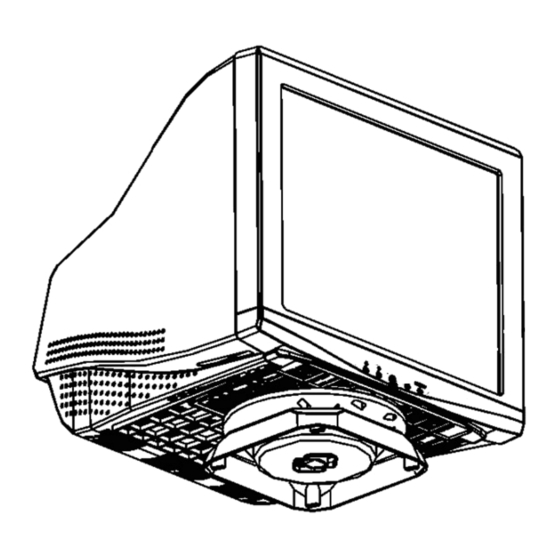
Page 38: Monitor Exploded View
17" CDT Color Monitor Lanix LX700R 11. Monitor Exploded View... -
Page 39: Bom List
17" CDT Color Monitor Lanix LX700R 12. BOM List S785FQRP2LT2 Location Part Number Description Remark 001C 503504 47 SCREW FOR CRT 005C600704075S CRT WASHER 011C 112500 WIRE MOUNT 011C6033 2 PCB SUPPORT 019C 403 7 STEEL 040C 581 26704 SHIPPING LABEL... - Page 40 17" CDT Color Monitor Lanix LX700R Q33C0103 1 LENS Q34C0141BCSA1A BEZEL 750A1697504JAL DEG. COIL 0.45X90TS E750A 750C5K56 1G CRT 17" CV CPTF 2nd Source E750A 750C5K56 2G 17" CV 0.18 GLARE CRT 2nd Source E750A 750C5W56 1G CRT 17" CV CPTF...
- Page 41 17" CDT Color Monitor Lanix LX700R T403 079C 167506 T FOCUS TRANSFORMER T402 079CP77550311F FBT FURI D954 093C3004500 SB340 095C205T 3005A WIRE H801 095C8013 6616 6PIN WIRE H802 095C8013 12637 12 PLUE 0D1C1140 7128 CR3 SCREW 0M1C1140 6128 CR3 SCREW...
- Page 42 17" CDT Color Monitor Lanix LX700R 006C 31 4 BRASS 006C 31 4 BRASS 006C 31 4 BRASS RV32 006C 31 4 BRASS RV31 006C 31 4 BRASS RV26 006C 31 4 BRASS RV20 006C 31 4 BRASS RV18 006C 31 4...
- Page 43 17" CDT Color Monitor Lanix LX700R J060 095C 90 23 JUMPER J059 095C 90 23 JUMPER J056 095C 90 23 JUMPER J055 095C 90 23 JUMPER J053 095C 90 23 JUMPER J052 095C 90 23 JUMPER J029 095C 90 23...
- Page 44 17" CDT Color Monitor Lanix LX700R R430 061C 60212352T CFR 12K OHM+-5% 1/6W R613 061C 60215352T CFR 15K OHM+-5% 1/6W R440 061C 60218252T CFR 1.8K OHM+-5% 1/6W R405 061C 60218252T CFR 1.8K OHM+-5% 1/6W R143 061C 60222252T CFR 2.2K OHM +-5% 1/6W...
- Page 45 17" CDT Color Monitor Lanix LX700R RV33 006C 31 4 BRASS RV34 006C 31 4 BRASS RV35 006C 31 4 BRASS RV36 006C 31501 BRASS RV37 006C 31501 BRASS RV38 006C 31501 BRASS RV29 006C 31502 BRASS IC105 056C 133503 T...
- Page 46 17" CDT Color Monitor Lanix LX700R C105 065C 44247013T 47PF +-5% NPO 50V C412 065C 444101 5T 100 PF 10% 50V Y5P C114 065C 444101 5T 100 PF 10% 50V Y5P C106 065C 444102 5T 1000 PF 10% 50V Y5P...
- Page 47 17" CDT Color Monitor Lanix LX700R C115 065C 444471 5T 470PF 10% 50V Y5P CRB795F2T9P CRT BOARD FOR B795F3-2P 009C 203 8 BRASS PIN P802 033C3278 6D WAFER P803 033C327812D WAFER*PLUG P801 033C380212B Y WAFER*PLUG 040C 45762412B LABEL R807 061C 208569 64 MOFR 5.6 OHM +-5% 1W...
- Page 48 17" CDT Color Monitor Lanix LX700R R819 061C1206304 RST CHIPR 300 KOHM +-5% 1/4W R837 061C1206304 RST CHIPR 300 KOHM +-5% 1/4W R844 061C1206304 RST CHIPR 300 KOHM +-5% 1/4W C862 065C0603101 316857 100PF 50V C858 065C0603101 316857 100PF 50V...
- Page 49 17" CDT Color Monitor Lanix LX700R FB802 071C 55 9 T CORE RF BEAD RH 3.5X6X0.76TP 006C 31 4 BRASS 715C1678 1 2 VIDEO BOARD PCB J801 095C 90 23 JUMPER J802 095C 90 23 JUMPER J803 095C 90 23...
- Page 50 17" CDT Color Monitor Lanix LX700R ZD801 093C 39147SEM BMM5V6 ZD802 093C 39147SEM BMM5V6 ZD803 093C 39147SEM BMM5V6 ZD804 093C 39147SEM BMM5V6 ZD805 093C 39147SEM BMM5V6 ZD806 093C 39147SEM BMM5V6 ZD807 093C 39147SEM BMM5V6 ZD808 093C 39147SEM BMM5V6 IC801 056C 366524...
Need help?
Do you have a question about the LX700R and is the answer not in the manual?
Questions and answers