Table of Contents
Advertisement
Quick Links
1. IMPORTANT SERVICE NOTES ........................................................................................................ 2
2. SPECIFICATIONS .............................................................................................................................. 5
3. PART NAMES .................................................................................................................................... 6
4. DISASSEMBLY OF THE SET ............................................................................................................ 7
5. MECHANISM ADJUSTMENT JIGS AND PARTS .............................................................................. 9
ITEMS AND INTERVALS ................................................................................................................. 10
7. MECHANICAL ADJUSTMENTS AND CHECKS .............................................................................. 11
8. TAPE RUNNING ADJUSTMENT ..................................................................................................... 14
(DISASSEMBLY AND REASSENBLY) ........................................................................................... 16
10.ADJUSTING THE ELECTRICAL CIRCUITS .................................................................................... 23
11.USEFUL TIPS ................................................................................................................................... 42
12.SIGNAL FLOW DIAGRAMS ............................................................................................................. 43
13.BLOCK DIAGRAMS ......................................................................................................................... 46
14.SCHEMATIC DIAGRAMS ................................................................................................................ 52
15.SEMICONDUCTOR LEAD IDENTIFICATION ............................................................................... 110
16.PRINTED WIRING BOARD ASSEMBLIES .................................................................................... 112
17.REPLACEMENT PARTS LIST ....................................................................................................... 141
18.PACKING OF THE SET ................................................................................................................. 161
SHARP CORPORATION
SERVICE MANUAL
LIQUID CRYSTAL DIGITAL CAMCORDER
MODEL
In the interests of user-safety (Required by safety regula-
tions in some countries) the set should be restored to its
original condition and only parts identical to those specified
be used.
CONTENTS
This document has been published to be used for
after sales service only.
The contents are subject to change without notice.
1
S21P4VL-WD650
VL-WD650U
Page
VL-WD650U
NTSC
Advertisement
Table of Contents

Related Manuals for Sharp VL-WD650U


Summary of Contents for Sharp VL-WD650U
-
Page 1: Table Of Contents
VL-WD650U SERVICE MANUAL S21P4VL-WD650 LIQUID CRYSTAL DIGITAL CAMCORDER NTSC VL-WD650U MODEL In the interests of user-safety (Required by safety regula- tions in some countries) the set should be restored to its original condition and only parts identical to those specified be used. -
Page 2: Important Service Notes
VL-WD650U 1. IMPORTANT SERVICE NOTES connections, metal cabinet, screw heads, knobs and BEFORE RETURNING THE VIDEO CAMERA control shafts, etc.) and measure the AC voltage drop RECORDER across the resistor. Reverse the AC plug (a non polarized adaptor plug must be used but only for the... - Page 3 VL-WD650U WARNING :TO REDUCE THE RISK OF FIRE OR ELECTRIC SHOCK, DO NOT EXPOSE THIS APPLIANCE TO WET LOCATIONS. CAUTION CAUTION RISK OF ELECTRIC SHOCK DO NOT OPEN This symbol mark means following. Camcorder only For continued protection against fire haz- CAUTION: TO REDUCE THE RISK OF ELECTRIC ard, replace only with same type fuse.
- Page 4 1-800-8-BATTERY or your local recycling center. If you are located outside the United States, contact your local authorities for information concerning proper disposal and/ or recycling of this battery. SHARP’s involvement in this program is part of our commitment to protecting our environment and conserving natural resources.
-
Page 5: Specifications
Specifications are subject to change without notice. SERVICE INFORMATION (For the U.S.) For the location of the nearest Sharp Authorized Service, or to obtain product literature, accessories, supplies or customer assistance, please call 1-800-BE SHARP (1-800-237-4277) or visit SHARP's website (http://www.sharp-usa.com) -
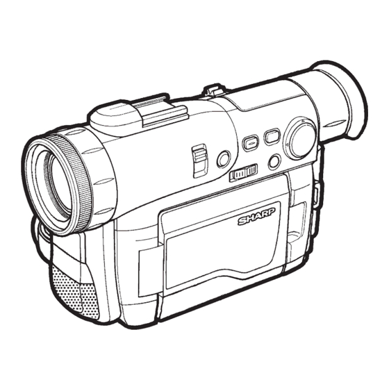
Page 6: Part Names
VL-WD650U 3. PART NAMES For details on the use of each control. Left view GAMMA/BRIGHTER button W/B (White Balance) button/ IR (Infrared) LIGHT button AUTO ON/OFF button Operation button SUPER CAT'S EYE switch Lens hood Zoom lens Infrared light transmitter/... -
Page 7: Disassembly Of The Set
VL-WD650U 4. DISASSEMBLY OF THE SET Note: Before removing the cabinet, turn off the power supply, and ascertain that the battery have been removed. Turn SW connector LCD FPC 1, 2 Joint main FPC 1) Disconnect the connector of the turn SW. - Page 8 VL-WD650U 1) Remove the screw ((a)LX-BZ0221TAFC)(1 pc.) to remove the cassette lid. 1) Disconnect the B TO B connector of the DV main FPC, disconnect the front and rear FPC connectors, and remove the screws ((c)XiPSF17P04000)(2 pcs.) to remove the main PWB.
-
Page 9: Mechanism Adjustment Jigs And Parts
VL-WD650U 5. MECHANISM ADJUSTMENT JIGS AND PARTS Configuration 1. Name 5-1. Mechanism check adjustment jigs 2. Part No. 3. Code <Note: The entries of list> * Model, Uses Remarks 1. Tension gauge 4N 1. PB-use cassette 1. Dial tension gauge 1. -
Page 10: Inspection And Maintenance Items And Intervals
VL-WD650U 6. INSPECTION AND MAINTENANCE ITEMS AND INTERVALS In order to keep the mechanical section always in good condition, perform the following inspection and maintenance at regular intervals. In addition, after repair, perform the following maintenance items regardless of how long the user has been using the unit. -
Page 11: Mechanical Adjustments And Checks
VL-WD650U 7. MECHANICAL ADJUSTMENTS AND CHECKS The items discussed here relate to general on-site servicing (field servicing). Adjustments and replacements that require sophisticated facilities, jigs and technology are omitted. In addition, in order to maintain the characteristics that the unit has when it is new, not only are inspection and maintenance necessary, but it is absolutely necessary that, for example, the tape not be damaged, and always use jigs for adjustments that require them. - Page 12 VL-WD650U 7-4. Back tension torque check and adjustment in record (playback) mode Tension roller position (S guide standard) AC adapter used, with cassette controller assembly 0 ± 0.3 (1) Checking Set the torque cassette (SD-1015), and make sure in the SP record mode that...
- Page 13 VL-WD650U <REW back tension standard> (If the tension fluctuates, read its center value.) 15 ± 12mN 7-8. Checking of winding Tu reel base ratchet torque DC3V, without cassette controller assembly (Independent Mechanism) (1) Remove the cassette controller assembly, then apply DC3V to the loading motor and put the system into standby mode.
-
Page 14: Tape Running Adjustment
VL-WD650U 8. TAPE RUNNING ADJUSTMENT 8-1. Adjustment locations <Replacement parts> Adjust the height of only · T roller, arm replaced parts with the · Tu guide, arm adjusting jig. · Slide chassis Adjustment procedure 8-2 Running rough Running final Running adjustm-... - Page 15 VL-WD650U 8-4. Running rough adjustment (With cassette controller) 1) Su, Tu guide roller height adjustment Entrance side Exit side <Method and description> ±1/4 shift ±1/4 shift Normal (1) Loosen the guide roller lock screw, then tighten loosely so that the roller turns easily.
-
Page 16: Disassembly And Reassembly
VL-WD650U 9. MECHANICAL SECTION ASSEMBLY AND PARTS REPLACEMENT (DISASSEMBLY AND REASSEMBLY) Mechanical section disassembly and reassembly are explained in this section. For removal of the cabinet, etc., refer to 4. DISASSEMBLY OF THE SET. <Precautions> 1. Always replace cut washers that have been removed, for example in parts replacement, with new ones. - Page 17 VL-WD650U (6) STOP mode (5) PLAYBACK (RECORD, FF, VSF) mode The system is in the STOP (Rec Lock in CAMERA mode) The mechanism position for playback, record, FF and fast position; the S and the T pole bases are snap-fitted to the drum feed playback.
- Page 18 VL-WD650U 9-3. How to operate with the circuit board without the cassette controller assembly. In this method, if the procedure is followed incorrectly there is danger of damaging the mechanism and the tape, so except in special cases, such as when measuring the VSR torque, do not perform this procedure. Normally operate this unit with the cassette controller assembly attached.
- Page 19 VL-WD650U 9-5. Reassembly 9-5-1. Reassembly in side of the main chassis. Note) Numbers before part names are given as a guide to the order of assembly. As for greasing/oiling/cleaning places refer to the attached drawings (Grease/Oil application side of the main chassis).
- Page 20 VL-WD650U 9-5-2. Reassembly in side of the Slide chassis. Note) Numbers before part names are given as a guide to the order of assembly. As for greasing/oiling/cleaning places refer to the attached drawings (Grease/Oil application side of the slide chassis)
- Page 21 VL-WD650U 9-5-3. Main chassis assembly and slide chassis assembly assembling method (1) Enter the coupling mode. (In this position, the cam groove of the T arm operation lever in the figure is parallel to the side of the main chassis, and the ball base is slightly moved.)
- Page 22 VL-WD650U GREASE/OIL APPLICATION From rear surface side Rear surface · groove side surface Front surface · rear surface · groove From rear side surface surface side Drum base assembly Main cam Loading lever Tu loading arm S loading arm Intermediate gear angle...
-
Page 23: Adjusting The Electrical Circuits
VL-WD650U 10. ADJUSTING THE ELECTRICAL CIRCUITS Before starting the electric circuit adjustment • The adjustment methods described herein are used, in most cases, when the expendable mechanical parts, including the video head, have been replaced, at which time the electrical circuits need to be readjusted. Before adjusting the electrical circuits, make sure that the mechanism works properly (i.e., the mechanism is properly adjusted). - Page 24 VL-WD650U VL-WD650U Service jig configuration...
- Page 25 VL-WD650U VL-WD650U Specifications of service jigs No. of pins New or Price Connection section Connector REF. No. Part cord Continuation code H/A_PWB–H/A_FPC P306– 80B-B QCNW-1832TAZZ H/A_FPC–MAIN –SC3301 80B-B CPWBH2876TA01 Product unit use MAIN–Battery Terminal SC900← DUNTK3063PM00 Product unit use —...
- Page 26 VL-WD650U [TEST POINT] (Wiring board diagram: Main Side B) TL6602(TELE MIC) Super-directional microphone check TL6604(GND) EE level check TL6607(INT MIC R) Frequency character check EE level check Frequency character check TL6605(INT MIC L) EE level check SC5002 P6602 Frequency character check...
- Page 27 VL-WD650U [Making adjustments] Adjusting the servo system controller and related parts 1. Setting the system codes Replacement of IC703 E PROM requires the following data to be set in this order. [Procedure] Set the unit to the VCR mode and set the data for each address.
- Page 28 VL-WD650U ADJUSTING THE ELECTROMAGNETIC CONVERSION CIRCUIT SYSTEM 1. PLL VCO adjustment Mode VCR ADJ mode Procedure 1) Playback the alignment tape (or a self-recorded tape). 2) Call the adjustment mode (V-ADJ). 3) Set the address "2A" and call the data.
- Page 29 VL-WD650U 2. PCO D/A-C adjustment Test point TL5002 Mode EE mode Procedure 1) Connect the AVS cable and then connect it to the monitor (TO). 2) Call the adjustment mode (V-ADJ). 3) Set the address to "23", and call the data.
- Page 30 VL-WD650U 3. COMMON PULSE adjustment Test point TL1801(C OUT) Address VCR ADJ 29(C) Mode VCR AV input Procedure 1) Connect TL1800 to GND. 2) With VCR ADJ 29, adjust the output voltage of TL1801 and the DC voltage value of the digital voltmeter to the specified adjustment values.
- Page 31 VL-WD650U (Wiring board diagram: Main Side B) R670 C3414 R3410 R3411 C3415 R636 R3415 C640 R638 R3404 R3442 R3406 TL8847(COM) C3406 Q3401 TL8845(VR) R631 C3465 R3441 C3403 VF COM-DC C3405 C3401 VF sub-contrast R/B R3496 C625 C3443 R3401 Q3406 R3489...
- Page 32 VL-WD650U 5. VF contrast adjustment Test point TL8846(VG) Address VCR ADJ E5 Mode VCR AV input Procedure 1) Input the signal of a 3-step waveform. 2) Set VCR ADJ EB/ED to FF/00. 3) Adjust the pedestal 100% range of the waveform of TL8846 to the specified adjustment value.
- Page 33 VL-WD650U ADJUSTING THE MIC AMP CIRCUIT (Wiring board diagram: Main Side B) TL6604(GND) EE level check Frequency character check TL6602(TELE MIC) Super-directional microphone check TL6607(INT MIC R) SC5002 P6602 EE level check P6601 Frequency character check C6621 R6628 TL604 TL6605(INT MIC L)
- Page 34 VL-WD650U DV INTERFACE (IEEE1394) ID SETTING This unit has a DV interface function conforming to IEEE1394. Therefore, each individual ID number must be used for each unit. Since this ID is written on the E PROM (IC302) on the head amp PWB, the ID must be newly written when replacing this IC or the head amp PWB.
- Page 35 VL-WD650U (5) Click on [Repair use]. Click (6) Input the necessary information for the application. For the indispensable input items, be sure to input them. Select the [Group/company] and [Kind name] from the list. Input the [Model name]. Input the [Serial number].
-
Page 36: Camera Section Adjustments
VL-WD650U 10-2. Camera Section Adjustments 10-2-1. Camera section service (1) Camera adjustment is performed after the set has been completed. (2) Subjects, measuring instruments and jigs needed for camera section service and adjustments • Gray scale chart • Frequency counter •... - Page 37 VL-WD650U 4) Operation flow FF or REW PLAY FF or REW PLAY STOP Address is selected and specified, with the data called. Then the called data are selected and fixed. The operation flows in this sequence. 5) When the adjustment is complete: Press the "CONTINUE"...
- Page 38 VL-WD650U (4) Camera signal system adjustment mode In the camera signal system adjustment mode, the automatic white balance is disabled to allow for the adjustment of the camera unit. At this time, the white balance mode is fixed at the INDOORS mode and the focus mode is switched to the manual focus mode.
- Page 39 VL-WD650U 10-2-4. Adjustment procedures Item Adjustment method (1) Auto-focus adjustment Set the unit to the auto-focus function adjustment mode and write data to the address "0000" one after another. This executed the adjustments automatically. The items to be adjusted are as listed below. Every time an adjustment is made properly, the data "FF"...
- Page 40 VL-WD650U Adjustment method Item (4) Iris AE coarse adjustment (1) Video output is observed with the oscilloscope in the grey scale standard record state, • Measurement terminal: the data of address "0002" is rewritten, and the luminance signal level is adjusted white to 735 ±...
- Page 41 VL-WD650U Item Adjustment method (1) White balance adjustment is performed repeatedly. (7) White balance adjustment • Measurement terminal: EE output • Address: "0090" INDOOR_W/B R "0092" INDOOR_W/B R • Measuring instrument: Vector scope • Object: Grey scale • Data variation width: "0000"...
-
Page 42: Useful Tips
VL-WD650U 11. USEFUL TIPS (PROBLEMS DIFFER FROM THOSE FOUND ON VHS OR 8MM DECKS BECAUSE THE SIGNALS ARE DIGITALLY PROCESSED.) Camera (REC mode) Camera (EE mode) Camera (REC mode) VCR (PB mode) VCR (PB mode) Blueback when Picture fails to... -
Page 43: Signal Flow Diagrams
VL-WD650U 12. SIGNAL FLOW DIAGRAMS 12-1. EE MODE FLOW (VIDEO) WAVEFORM DIAGRAM (DURING COLOR BAR RECORDING) IC4401 249pin Y/YC Output CH1=500mV 20µs/d DC P*10 CAM ADIN 117 118 IC4401 170pin ZYP3 Input IC202 CAM ENGINE 5ms/d CH1=1V DC P*10 84 85... - Page 44 VL-WD650U WAVEFORM DIAGRAM 12-3. FLOW IN PB MODE (VIDEO) (DURING COLOR BAR PLAYBACK) IC3401 39pin PBDATA Input IC3401 32pin Output HEAD AMP 5ms/d 5ms/d CH1=500mV CH1=500mV PB_DATA DC P*10 DC P*10 SC3301 B TO B PB_DATA IC3401 EQ/PLL IC3401 44pin Input...
- Page 45 VL-WD650U 12-5. FLOW IN PB MODE (AUDIO) WAVEFORM DIAGRAM (1.6 kHz SINE WAVE) From IC3404 same as in Video PB system 10µs/d CH1=1V DC P*10 IC452 REC/PB ENGINE DODAT 16Bit ADC/DAC IC1602 AUD-R_DA_OUT AUD-L_DA_OUT IC601 AUDIO I/O Headphone Jack AUDIO-R_IN/OUT...
-
Page 46: Block Diagrams
VL-WD650U 13. BLOCK DIAGRAMS 13-1. SYSTEM BLOCK DIAGRAM... - Page 47 VL-WD650U 13-2. CAMERA SECTION BLOCK DIAGRAM...
- Page 48 VL-WD650U 13-3. VIO ENGINE SECTION BLOCK DIAGRAM...
- Page 49 VL-WD650U 13-4. REC/PB SECTION BLOCK DIAGRAM...
- Page 50 VL-WD650U 13-5. AUDIO/DIGITAL OUTPUT SECTION BLOCK DIAGRAM...
- Page 51 VL-WD650U 13-6. CAMERA CIRCUIT BLOCK DIAGRAM...
-
Page 52: Schematic Diagrams
VL-WD650U/K 14. SCHEMATIC DIAGRAMS 14-1. OVERALL SCHEMATIC DIAGRAM 52~53... - Page 53 VL-WD650U/K 14-2. TG SCHEMATIC DIAGRAM 54~55...
- Page 54 VL-WD650U/K 14-3. CDS SCHEMATIC DIAGRAM 56~57...
- Page 55 VL-WD650U/K 14-4. CAMERA ENGINE SCHEMATIC DIAGRAM 58~59...
- Page 56 VL-WD650U/K 14-5. LENS DRIVE SCHEMATIC DIAGRAM 60~61...
- Page 57 VL-WD650U/K 14-6. AUDIO I/O SCHEMATIC DIAGRAM 62~63...
- Page 58 VL-WD650U/K 14-7. MEC/SYS_MICON SCHEMATIC DIAGRAM 64~65...
- Page 59 VL-WD650U/K 14-8. VIDEO I/O SCHEMATIC DIAGRAM 66~67...
- Page 60 VL-WD650U/K 14-9. MOTOR DRIVER SCHEMATIC DIAGRAM 68~69...
- Page 61 VL-WD650U/K 14-10. LCD_DISPLAY SCHEMATIC DIAGRAM 70~71...
- Page 62 VL-WD650U/K 14-11. POWER1 SCHEMATIC DIAGRAM 72~73...
- Page 63 VL-WD650U/K 14-12. CONNECTION(B-B) SCHEMATIC DIAGRAM 74~75...
- Page 64 VL-WD650U/K 14-13. EQ/PLL SCHEMATIC DIAGRAM 76~77...
- Page 65 VL-WD650U/K 14-14. CAM/CARD_MICON SCHEMATIC DIAGRAM 78~79...
- Page 66 VL-WD650U/K 14-15. VIO ENGINE SCHEMATIC DIAGRAM 80~81...
- Page 67 VL-WD650U/K 14-16. DAC SCHEMATIC DIAGRAM 82~83...
- Page 68 VL-WD650U/K 14-17. CONN1 SCHEMATIC DIAGRAM 84~85...
- Page 69 VL-WD650U/K 14-18. MIC AMP SCHEMATIC DIAGRAM 86~87...
- Page 70 VL-WD650U/K 14-19. VF SCHEMATIC DIAGRAM 88~89...
- Page 71 VL-WD650U/K 14-20. CONN2 SCHEMATIC DIAGRAM 90~91...
- Page 72 VL-WD650U/K 14-21. REC/PB ENGINE JOG SCHEMATIC DIAGRAM 92~93...
- Page 73 VL-WD650U/K 14-22. CCD SCHEMATIC DIAGRAM 94~95...
- Page 74 VL-WD650U/K 14-23. POWER SCHEMATIC DIAGRAM å AND SHADED COMPONENTS=SAFETY RELATED PARTS å å 96~97...
- Page 75 VL-WD650U/K 14-24. LCD_DISPLAY2 SCHEMATIC DIAGRAM å AND SHADED COMPONENTS=SAFETY RELATED PARTS å 98~99...
- Page 76 VL-WD650U/K 14-25. IR, ZOOM-MIC, JOINT SCHEMATIC DIAGRAM PLUS TERMINAL QTANS9041TAFW MiNUS TERMINAL QTANS9042TAFW 100~101...
- Page 77 VL-WD650U/K 14-26. DV 232C HP SCHEMATIC DIAGRAM 102~103...
- Page 78 VL-WD650U/K 14-27. VCR OPE SCHEMATIC DIAGRAM 104~105...
- Page 79 VL-WD650U/K 14-28. AVS DC JACK SCHEMATIC DIAGRAM 106~107...
- Page 80 VL-WD650U/K 14-29. HEAD AMP SCHEMATIC DIAGRAM 108~109...
-
Page 81: Semiconductor Lead Identification
VL-WD650U 15. SEMICONDUCTOR LEAD IDENTIFICATION 3LN01S 2SC4627CD HN2A01FU 2SA1989R FC117 HN1B04FU 2SB12956 UN9214 CPH6701 HN2C01FU 2SC4738Y CPH3209 TK11813M RN4990 FMMT717 CPH3109 RN4984 XP05534 2SC5383F RT1P441U RN4982 CPH3206 RN1907 2SA1588Y HN1CO1FU RT1N441U BAV756S MC2852 S81230SG TA75S01F RN1704 TC7S08U 580925AN TA7SL02U 2SC4944Y... - Page 82 VL-WD650U MA729 RD2R7UM0 MA2S111 HVU17TRF HVU350B EX1394CE HVU359TR HVC359TR MI1A3 EX1399CE MB88344F ADS933Y IX0818TA UPC2391G LB11990W IX0819TA MM1449XQ BH7277KV TL1454PW CXA2096N NJM2904V BBH7761KV BH7275KV ADC08351 MS548331 NJM2902V IX0748TA MB3825A PCM3006T LV4051AT NJM3414V BA7761KV AN2536FH MM1323XV LA7473V MB8346BV LR38610 VHCT04AT M40C558V...
-
Page 83: Printed Wiring Board Assemblies
VL-WD650U 16. PRINTED WIRING BOARD ASSEMBLIES MAIN PWB Component Side SIDE A C5003 L5001 C5004 R5010 C5005 R5009 P801 IC5001 C5001 C5006 R5011 R5012 C5002 R5002 R1950 R5016 R5017 R5018 P5001 C5007 C5009 C5008 C711 X702 IC703 IC702 R703 R701... - Page 84 VL-WD650U Wiring Side SIDE A...
- Page 85 VL-WD650U Component Side SIDE B P6602 SC5002 P6601 C6621 R6628 C6628 R5801 C6604 R5800 R6602 L2800 C2800 L2801 C2801 R6633 C6611 R6635 R2804 R2803 R6615 R6616 R6619 R2808 R2806 R6617 R2807 R2805 R6636 C6618 R6621 R6620 R6624 C6634 Q6603 C6619 C6617...
- Page 86 VL-WD650U Wiring Side SIDE B...
- Page 87 VL-WD650U SUB PWB Component Side SIDE A C1603 C1604 R1662 C1610 C1605 C1601 C467 C1607 R5201 C1608 R7410 L1601 R1602 R1603 C1614 C1617 C1609 R5202 R1604 C1611 R5203 C462 IC408 FB456 C456 C465 Wiring Side SIDE A...
- Page 88 VL-WD650U Component Side SIDE B C404 R414 R407 IC401 R7420 C405 C473 C421 X401 R477 R430 D472 R478 R433 L471 C474 D471 C418 R418 R417 C419 TL402 R7402 C7417 D7402 R7419 R7417 D7401 C413 R7418 C430 R454 C7401 IC452 R7422...
- Page 89 VL-WD650U CCD PWB Component Side SIDE A TL13 TL11 TL91 TL10 TL18 TL19 TL93 TL92 TL17 TL16 TL15 TL14 TL12 Wiring Side SIDE A...
- Page 90 VL-WD650U Component Side SIDE B Wiring Side SIDE B...
- Page 91 VL-WD650U POWER PWB Component Side SIDE A R9905 C9900 R946 R932 R934 TL919 R935 R936 R9916 TL901 TL900 R948 TL911 R9917 C9904 R9908 R9910 R9909 C9901 C986 L961 R9907 R9911 TL905 FB9900 TL923 TL904 C983 Q9902 TL929 TL902 Q9905 L962...
- Page 92 VL-WD650U Wiring Side SIDE A...
- Page 93 VL-WD650U Component Side SIDE B C918 R926 Q9913 C907 R944 R945 C919 R910 R915 R912 R913 R941 C917 R953 R9933 R909 R971 Q9906 R908 Q9910 R905 C904 C9911 R9925 Q9912 Q9908 IC900 C922 R9931 C908 R9912 C901 R9928 R978 C902...
- Page 94 VL-WD650U Wiring Side SIDE B...
- Page 95 VL-WD650U JOINT PWB Component Side SIDE A SC2024 BAT2021 SC2023 SC2022 Wiring Side SIDE A...
- Page 96 VL-WD650U Component Side SIDE B R2021 TL2034 R2022 TL2072 TL2070 TL2069 TL2067 R2023 TL2071 TL2031 R2024 R2025 TL2066 TL2064 R2026 TL2040 TL2062 TL2061 TL2060 TL2059 TL2063 R2027 TL2032 TL2030 TL2028 TL2027 TL2025 TL2058 TL2037 TL2057 TL2056 TL2042 TL2043 TL2041 TL2055...
- Page 97 VL-WD650U DV/PC CONNECTION PWB Wiring Side SIDE A Component Side SIDE A J2002 J2001 R2001 J2003...
- Page 98 VL-WD650U Component Side SIDE B Wiring Side SIDE B FL2001...
- Page 99 VL-WD650U OPERATION PWB Component Side SIDE A Wiring Side SIDE A SW2051 SW2056 SW2057 SW2058 SW2052 SW2055 SW2053 SW2054...
- Page 100 VL-WD650U Component Side SIDE B Wiring Side SIDE B...
- Page 101 VL-WD650U AVS DC JACK PWB Component Side SIDE A J2011 SW2013...
- Page 102 VL-WD650U Wiring Side SIDE A...
- Page 103 VL-WD650U Component Side SIDE B TL2203 TL2204 TL2202 TL2201 TL2206 TL2205 TL2207 TL2211 TL2228 R2011 FL2011 TL2227 FL2012 TL2226 TL2236 TL2225 TL2208 TL2209 TL2210 R2014 TL2224 TL2223 TL2221 TL2219 R2013 TL2220 TL2218 TL2222 TL2214 TL2212 TL2213 TL2238 TL2239 TL2217 FL2013...
- Page 104 VL-WD650U Wiring Side SIDE B...
- Page 105 VL-WD650U LCD PWB Component Side SIDE A L9801 C9803 C9810 C9809 Q9801 T9800 L9800 R9817 R9816 D9800 C9806 R9808 R9813 FB3801 R3819 C9812 R9812 R3800 R3813 R3810 C3802 C3803 R3802 C3821 C3810 D3801 R3827 C3820 R3811 R3826 R3818 C3809 R3817...
- Page 106 VL-WD650U Wiring Side SIDE A...
- Page 107 VL-WD650U Wiring Side SIDE B...
- Page 108 VL-WD650U REMOCON/IR PWB Wiring Side SIDE A Component Side SIDE A RMC2041 D2042 D2041 Wiring Side SIDE B Component Side SIDE B...
- Page 109 VL-WD650U HEAD AMP PWB Component Side SIDE A R332 C320 C315 R330 R331 R333 R321 R308 C322 C304 R320 Q302 C331 C307 C330 R318 P306 C305 R312 C324 C311 R323 C319 R304 R325 C333 Q303 C301 C327 R324 C342 C332...
- Page 110 VL-WD650U Component Side SIDE B C345 L301 C303 Wiring Side SIDE B...
- Page 111 VL-WD650U ZOOM-MIC JACK PWB Wiring Side SIDE A Component Side SIDE A J2041 Wiring Side SIDE B...
-
Page 112: Replacement Parts List
RH-iX0853TAZZQ IX0853TA, Mecha/System BC " HOW TO ORDER REPLACEMENT PARTS " Micon IC702 VHiRS5C313/-1 RS5C313, Timer in USA: Contact your nearest SHARP Parts Distributor. For loca- IC703 VHiBR24C08F-1 BR24C08F, E PROM tion of SHARP Parts Distributor, IC704 VHiNJM2143R-1 NJM2143R, Servo Error... - Page 113 VL-WD650U Ref. No. Part No. Description Code Ref. No. Part No. Description Code Q1900 VSiMD16A///-1 IMD16A L8801 VPMAN100MR50N Peaking, 10µH Q1901 VS2SC4213B/-1 2SC4213B L8804 VPMAN100MR50N Peaking, 10µH Q1903 VSRN4984///-1 RN4984 L8805 VPD9M470K4R1N Peaking, 47µH Q1904 VSiMD16A///-1 IMD16A Q1905 VSRN4984///-1 RN4984...
- Page 114 VL-WD650U Ref. No. Part No. Description Code Ref. No. Part No. Description Code C1418 VCKYCZ1CB103K 0.01 16V Ceramic C569 VCKYCZ1AF104Z 10V Ceramic C1431 VCSATE1AJ476M 10V Tantalum C570 VCCCCZ1HH151J 150p 50V Ceramic C1432 VCKYCZ1CB103K 0.01 16V Ceramic C571 VCKYCZ1HF103Z 0.01 50V Ceramic...
- Page 115 VL-WD650U Ref. No. Part No. Description Code Ref. No. Part No. Description Code C3428 VCKYTV1CB224K 0.22 16V Ceramic C4465 VCKYCZ1AB104K 10V Ceramic C3429 VCKYCZ1HB102K 1000p 50V Ceramic C4466 VCKYCZ1CB103K 0.01 16V Ceramic C3430 VCKYCZ1AF104Z 10V Ceramic C4472 VCKYCZ1CB103K 0.01 16V Ceramic...
- Page 116 VL-WD650U Ref. No. Part No. Description Code Ref. No. Part No. Description Code C8808 VCKYTV1CB105K 16V Ceramic R563 VRS-CZ1JF104D 100k 1/16W Metal Oxide C8809 VCKYCZ1CB103K 0.01 16V Ceramic R564 VRS-CZ1JF103D 10k 1/16W Metal Oxide C8810 VCCCCZ1HH330J 50V Ceramic R565 VRS-CZ1JF223J...
- Page 117 VL-WD650U Ref. No. Part No. Description Code Ref. No. Part No. Description Code R730 VRS-CZ1JF104J 100k 1/16W Metal Oxide R1708 VRS-CZ1JF1R0J 1/16W Metal Oxide R731 VRS-CZ1JF102J 1/16W Metal Oxide R1709 VRS-CZ1JF1R0J 1/16W Metal Oxide R732 VRS-CZ1JF104J 100k 1/16W Metal Oxide...
- Page 118 VL-WD650U Ref. No. Part No. Description Code Ref. No. Part No. Description Code R3415 VRS-CZ1JF151J 150 1/16W Metal Oxide R3732 VRS-CZ1JF102J 1/16W Metal Oxide R3416 VRS-CZ1JF221J 220 1/16W Metal Oxide R3735 VRS-CZ1JF102J 1/16W Metal Oxide R3417 VRS-CZ1JF221J 220 1/16W Metal Oxide...
- Page 119 VL-WD650U Ref. No. Part No. Description Code Ref. No. Part No. Description Code R7857 VRS-CZ1JF564J 560k 1/16W Metal Oxide R4494 VRS-CZ1JF000J 1/16W Metal Oxide R7858 VRS-CZ1JF564J 560k 1/16W Metal Oxide R4499 VRS-CZ1JF000J 1/16W Metal Oxide R5002 VRS-CZ1JF102J 1/16W Metal Oxide...
- Page 120 VL-WD650U Ref. No. Part No. Description Code Ref. No. Part No. Description Code Q7403 VS2SC5383F/-1 2SC5383F C7400 RC-KZ0083TAZZ 10V Ceramic C7401 RC-KZ0083TAZZ 10V Ceramic DIODES C7402 VCKYCZ1CB103K 0.01 16V Ceramic C7403 VCKYCZ1CB103K 0.01 16V Ceramic D403 VHDHVU362//-1 HVU362 C7404 VCKYCZ1EB472K...
- Page 121 VL-WD650U Ref. No. Part No. Description Code Ref. No. Part No. Description Code Q9908 VS2SA1989R/-1 2SA1989R MISCELLANEOUS PART Q9909 VSHN1C01FU/-1 HN1C01FU SC5201 QCNCW9389TAZZ Connector, 120Pin Q9910 VSRN4984///-1 RN4984 Q9911 VSNDS332P//-1 NDS332P Q9912 VSRN4990///-1 RN4990 Q9913 VS2SC5383F/-1 2SC5383F DUNTK3046PM00 Q9914 VSRT1N441U/-1...
- Page 122 VL-WD650U Ref. No. Part No. Description Code Ref. No. Part No. Description Code C981 RC-KZ0044TAZZ 10V Ceramic R9900 VRS-CZ1JF153J 15k 1/16W Metal Oxide C982 RC-KZ0044TAZZ 10V Ceramic R9901 VRS-CZ1JF682J 6.8k 1/16W Metal Oxide C983 VCKYTV1AB105K 10V Ceramic R9902 VRS-CZ1JF561J 560 1/16W Metal Oxide...
- Page 123 VL-WD650U Ref. No. Part No. Description Code Ref. No. Part No. Description Code RESISTORS C3807 VCKYCZ1HF103Z 0.01 50V Ceramic C3809 VCKYCZ1CB103K 0.01 16V Ceramic R2021 VRS-CZ1JF363D 36k 1/16W Metal Oxide C3811 VCKYCZ1CB103K 0.01 16V Ceramic R2022 VRS-CZ1JF123D 12k 1/16W Metal Oxide...
- Page 124 VL-WD650U Ref. No. Part No. Description Code Ref. No. Part No. Description Code SW2059 QSW-S0210TAZZ Switch, Card/Tape SW C312 VCKYCZ1HB102K 1000p 50V Ceramic TP2051 QLUGP0111TAFW C313 VCKYCZ1HB102K 1000p 50V Ceramic C314 VCKYCZ1AF104Z 10V Ceramic C315 VCKYCZ1HB102K 1000p 50V Ceramic C318...
- Page 125 VL-WD650U Ref. No. Part No. Description Code Ref. No. Part No. Description Code MSPRP0185GEZZ PB Guide SPR. MECHANISM PARTS LX-WZ1071GE02 CW ø 0.7 ø 1.8t0.1 LX-WZ1104GE06 CW ø 0.7 ø 2.2t0.25 LCHSM0181GEZZ Main Chassis Ass’y LX-WZ1029GE00 CW ø 1.2 ø 3t0.25...
- Page 126 VL-WD650U Ref. No. Part No. Description Code Ref. No. Part No. Description Code CABINET PARTS LIST GCOVH1272TA00 Eye Cap GCOVH1275TAZZ V/F Front Cover Unit JKNBZ0096TASA Visibility Control Knob DCABA6222LM01 Cabinet A Preparation LANGK0602TAZZ V/F Tilt Unit 1-1-2 GCOVH1274TASA DV Terminal Cover...
- Page 127 VL-WD650U Ref. No. Part No. Description Code Ref. No. Part No. Description Code LX-HZ0063TAFN Screw SUPPLIED ACCESSORIES LX-HZ0079TAFD Screw LX-HZ0050TAFF Screw LX-BZ0246TAFD Screw ACCESSORIES LX-BZ0247TAFF Screw å QACCD0031TAPZ AC Cord(WD650U) LX-HZ0017TAFF Screw å QACCZ0053TAPZ AC Cord(WD650UK) QCNW-2016TAZZ A/V Cable QCNW-1957TAZZ...
- Page 128 VL-WD650U MECHANISM CHASSIS EXPLODED VIEW Ref. No. Part No. Description Code Ref. No. Part No. Description Code 1 pc. 411~ 411~ 1 pc.
- Page 129 VL-WD650U CABINET EXPLODED VIEW Ref. No. Part No. Description Code Ref. No. Part No. Description Code 7-16 4-15 7-20 7-21 7-11 7-22 7-18 7-19 7-17 4-11 7-14 7-13 2-10 4-13 4-9 7-12 7-15 7-10 4-14 4-1-2 4-12 4-10 8-4-2 8-3-2...
- Page 130 VL-WD650U CASSETTE CONTROL EXPLOOD VIEW Ref. No. Part No. Description Code Ref. No. Part No. Description Code CAMERA UNIT EXPLOOD VIEW...
- Page 131 VL-WD650U VL-WD650U SERVICE JIG SPECIFICATIONS Ref. No. Part No. Description Code Ref. No. Part No. Description Code 1-1. Adjusting jigs for checking the mechanism Name New part Type number, Application Part code Code PB-use cassette torque meter 1mN·m/15mN·m 9DASD-1015 Torque gauge...
-
Page 132: Packing Of The Set
VL-WD650U 18. PACKING OF THE SET Ref. No. Part No. Description Code Ref. No. Part No. Description Code åQACCD0031TAPZ(WD650U) QCNW-2016TAZZ åQACCZ0053TAPZ(WD650UK) (A/V Cable) (AC Cord) åUADP-0321TAZZ(WD650U) UBNDS0010TASA åUADP-0328TAZZ(WD650UK) (Shoulder Strap) (AC Adaptor) QCNW-2022TAZZ SPAKF0277TAZZ (232C Cable) (Packing Add.) SPAKA6376TAZZ (Packing Add. (Top)) - Page 133 Part No. Description Code © COPYRIGHT 2001 BY SHARP CORPORATION ALL RIGHTS RESERVED. No part of this publication may be reproduced, stored in a retrieval system, or transmitted in any form or by any means, electronic, mechanical, photocopying, recording, or otherwise, without prior written permission of the publisher.
Need help?
Do you have a question about the VL-WD650U and is the answer not in the manual?
Questions and answers