Table of Contents
Advertisement
Advertisement
Table of Contents

Related Manuals for LG LWC183MGMJ1


Summary of Contents for LG LWC183MGMJ1
-
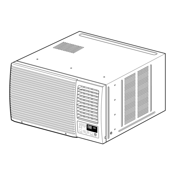
Page 1: Room Air Conditioner
ROOM AIR CONDITIONER SERVICE MANUAL CAUTION - BEFORE SERVICING THE UNIT, READ THE "SAFETY PRECAUTIONS" IN THIS MANUAL. - ONLY FOR AUTHORIZED SERVICE MODELS: LWC183MGMJ1, LWC183MSMM1, LWC183MGAB1... -
Page 2: Table Of Contents
CONTENTS 1. PREFACE 1.1 SAFETY PRECAUTIONS..........................3 1.2 INSULATION RESISTANCE TEST.........................3 1.3 SPECIFICATIONS............................3 1.4 FEATURES ..............................4 1.5 CONTROL LOCATIONS ..........................4 2. DISASSEMBLY INSTRUCTIONS 2.1 MECHANICAL PARTS ............................6 2.1.1 FRONT GRILLE .............................6 2.1.2 CABINET..............................6 2.1.3 CONTROL BOX .............................6 2.2 AIR HANDLING PARTS ..........................7 2.2.1 COVER (AT THE TOP) ..........................7 2.2.2 BLOWER..............................7 2.2.3 FAN ................................7... -
Page 3: Preface
Mode [except POWER OFF]. 4. The value should be over 1 MΩ. 1.3 SPECIFICATIONS MODELS LWC183MGMJ1 LWC183MSMM1 LWC183MGAB1 ITEMS POWER SUPPLY 1Ø,208/230V,60Hz... -
Page 4: Features
1.4 FEATURES • Side air-intake, side cooled-air discharge. • Designed for cooling only. • Built in adjustable THERMISTOR. • Powerful and quiet cooling. • Washable one-touch filter. • Slide-in and slide-out chassis for the simple installation and service. • Compact size. •... - Page 5 DISPLAY REMOTE CONTROL Temp Power Mode Timer Auto Auto Restart Swing Precaution: The Remote Control unit will not function properly if strong light strikes the sensor window of the air conditioner or if there are obstacles between the Remote Control unit and the air conditioner. POWER BUTTON Operation starts, when this button is pressed and stops when you press the button again.
-
Page 6: Disassembly Instructions
2. DISASSEMBLY INSTRUCTIONS — Before the following disassembly, POWER SWITCH is set to OFF and disconnected the power cord. 2.1 MECHANICAL PARTS 2.1.1 FRONT GRILLE 1. Open the inlet grille upward or downward. 2. Remove the screw which fastens the front grille. 3. -
Page 7: Air Handling Parts
2.2 AIR HANDLING PARTS 2.2.1 COVER (AT THE TOP) 1. Remove the front grille. (Refer to section 2.1.1) 2. Remove the cabinet. (Refer to section 2.1.2) 3. Remove 11 screws which fasten the brace and covers. 4. Remove the covers and the brace. (See Fig. 4) 5. -
Page 8: Shroud
2.2.4 SHROUD 1. Remove the fan. (Refer to section 2.2.3) 2. Remove the 2 screws which fasten the shroud. 3. Remove the shroud. (See Fig. 8) 4. Re-install the component by referring to the removal procedure, above. 2.3 ELECTRICAL PARTS 2.3.1 MOTOR Figure 8 (a) Figure 8 (b) -
Page 9: Power Cord
2.3.4 POWER CORD 1. Remove the control box. (Refer to section 2.1.3) 2. Unfold the control box. (Refer to section 2.3.3) 3. Disconnect the grounding screw from the control box. 4. Disconnect 2 receptacles. 5. Remove a screw which fastens the clip cord. 6. -
Page 10: Refrigeration Cycle
2.4 REFRIGERATION CYCLE CAUTION Discharge the refrigerant system using Freon Recovery System. If there is no valve to attach the recovery system, install one (such as a WATCO A-1) before venting the Freon . Leave the valve in place after servicing the system. 2.4.1 CONDENSER 1. - Page 11 NOTES — Replacement of the refrigeration cycle. 1. When replacing the refrigeration cycle, be sure to 6. Recharge as follows : discharge the refrigerant system using a Freon 1) Refrigeration cycle systems are charged from the recovery System. High-side. If the total charge cannot be put If there is no valve to attach the recovery system, in the High-side, the balance will be put in the install one (such as a WATCO A-1) before venting...
- Page 12 Equipment needed: Vacuum pump, Charging cylinder, Manifold gauge, Brazing equipment. Pinch-off tool capable of making a vapor-proof seal, Leak detector, Tubing cutter, Hand Tools to remove components, Service valve. Figure 17A-Pulling Vacuum Figure 17B-Charging —12—...
-
Page 13: Outside Dimensions
3. TROUBLESHOOTING GUIDE 3.1 OUTSIDE DIMENSIONS 675(770) 3.2 PIPING SYSTEM CONDENSER COIL CAPILLARY TUBE MOTOR COMPRESSOR BLOWER EVAPORATOR COIL Following is a brief description of the important components and their functions in the refrigeration system. Refer to Fig. 18 to follow the refrigeration cycle and the flow of the refrigerant in the cooling cycle. ROOM AIR CONDITIONER CYCLE OF REFRIGERATION EVAPORATOR COILS... - Page 14 3.3 TROUBLESHOOTING GUIDE In general, possible trouble is classified in two causes. The one is called Starting Failure which is caused from an electrical defect, and the other is Ineffective Air Conditioning caused by a defect in the refrigeration circuit and improper application. Unit runs but poor cooling Ineffective Cooling Check of cold air circulation...
- Page 15 Fails to Start Check of power source. Check of circuit breaker and fuse. Check of control switch Check of control panel. setting. Only compressor fails to Only fan fails to start. start. Improper wiring. Drop of power voltage. Improper thermistor setting Defect of fan motor capacitor.
- Page 16 ELECTRIC PARTS TROUBLESHOOTING GUIDE: MODEL: LWC183MGMJ1, LWC183MSMM1 Possible Trouble 1 • The unit does not operate. • Check the Fuse. Is the Trans output power the • Check the wiring diagram. same as specified? • Check the Main Is the Trans output power Is shorted the Trans.
- Page 17 Possible Trouble 2 • The compressor does not operate. Is Temp. setting set lower than Room • Set the Temp. setting to higher Temp. Temp.-0.5°C? Is the voltage No.10 Is the voltage N0.7 of Is the Unit for 3 minutes of IC01M 0V? IC01M DC 5V? delay?
- Page 18 • The function of Energy Saver does not operate. Possible Trouble 5 • Set the Knob of SW1 Is the Knob of SW1 to left position. set to left position? • Check the SW1. Is the voltage No.1 of • Check the pattern of CN-DISP of Main PCB Main &...
- Page 19 Possible Trouble 7 • It displays abnormally on Display P.W.B Ass'y. • Exchange IC01G. Is the IC01G all right? • Connect connector Is the connection of to CN-DISP1 exactly. CN-DISP1 all right? Does the Q01G, Q02G, Q03G Q04G operate normally •...
- Page 20 ROOM AIR CONDITIONER VOLTAGE LIMITS NAME PLATE RATING MINIMUM MAXIMUM 208~230 ± 10% 187V 253V COMPLAINT CAUSE REMEDY Fan motor will not run. No power Check voltage at outlet. Correct if none. Power supply cord Check voltage to rotary switch. If none, check power supply cord.
- Page 21 COMPLAINT CAUSE REMEDY Fan motor noise. If cracked, out of balance, or partially missing, replace it. Blower If cracked, out of balance, or partially missing, replace it. Loose set screw Tighten it. Worn bearings If knocking sounds continue when running or loose, replace the motor.
- Page 22 COMPLAINT CAUSE REMEDY Compressor cycles on Fan motor If not running, determine the cause. Replace if overload. required. Condenser air flow Remove the cabinet, inspect the interior surface restriction of the condenser. If restricted, clean carefully with a vacuum cleaner (do not damage fins) or brush.
-
Page 23: Schematic Diagram
5. SCHEMATIC DIAGRAM 5.1 CIRCUIT DIAGRAM POWER INPUT POWER INPUT WH(BL) BK(BR) BK(BR) WH(BL) (Ribbed) (Plain) (Plain) (Ribbed) GN/YL(GN) THERMISTOR CN-TH1 MOTOR OR(BR) OR(BR) GN/YL (GN) CAPACITOR OR(BR) SYNC MOTOR RY-SYNC SYNC. M. RY-COMP COMP. TRANS FORMER FUSE 250V/T2A (115V/T2A) 3854AR2330P WIRING DIAGRAM WIRING DIACRAM... -
Page 24: Electronic Control Device
5.2. ELECTOINC CONTROL DEVICE MODEL: LWC183MGMJ1, LWC183MSMM1 —24—... -
Page 25: Components Location(For Main P.c.b Asm)
5.3. COMPONENTS LOCATION (FOR MAIN P.C.B ASM) MODEL: LWC183MGMJ1, LWC183MSMM1 5.4. COMPONENTS LOCATION (FOR DISPLAY P.C.B ASM) MODEL: LWC183MGMJ1, LWC183MSMM1 —25—... -
Page 26: Exploded View
6. EXPLODED VIEW 554030 148000 130910 W48602 559010 149980 352390 349600 130410 346811 731273 554160 359012 550140 349480 354210 W52106-1 W52106-2 147582 349001 W48602 552102 352115 267110 352113 352111 249950 135312 263230 35211A W0CZZ 152302 249950 135313 135303 268712 269310 237200 238310 135510... -
Page 27: Replacement Parts List
7. REPLACEMENT PARTS LIST R: Service Parts PART NO. LOCATION DESCRIPTION REMARK LWC183MGMJ1 LWC183MSMM1 LWC183MGAB1 130410 BASE ASSEMBLY,SINGLE 3041A30002B 130910 CABINET ASSEMBLY,SINGLE 3091AR6057B 135312 GRILLE ASSEMBLY,FRONT 3531A20005L 3531A20073E 3531A20005A 135313 GRILLE,INLET 3530AR1604A 3530AR1603A 3530AR1604A 135500 COVER,CONTROL BOX 3551A30015A 137215 PANEL ASSEMBLY,CONTROL... - Page 28 February, 2003 P/No.: 3828A20294E Printed in Korea...
Need help?
Do you have a question about the LWC183MGMJ1 and is the answer not in the manual?
Questions and answers