Table of Contents
Advertisement
ASCON spa
ISO 9001
C e r t i f i e d
ASCON spa
20021 Bollate
(Milano) Italy
via Falzarego, 9/11
Tel. +39 02 333 371
Fax +39 02 350 4243
http://www.ascon.it
e-mail sales@ascon.it
Temperature
Controller
1
/
DIN - 48 x 48
16
M3 line
U s e r m a n u a l • M . I . U . M 3 - 4 / 0 3 . 0 1 • C o d . J 3 0 - 4 7 8 - 1 A M 3 I E
c
c
C
US
U L
LISTED
Advertisement
Table of Contents

Related Manuals for ascon M3 Series


Summary of Contents for ascon M3 Series
- Page 1 DIN - 48 x 48 ASCON spa M3 line ISO 9001 U s e r m a n u a l • M . I . U . M 3 - 4 / 0 3 . 0 1 • C o d . J 3 0 - 4 7 8 - 1 A M 3 I E...
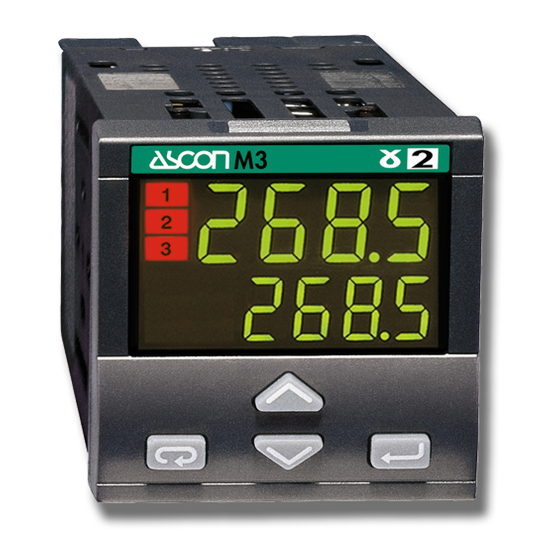
- Page 2 Temperature Controller DIN - 48 x 48 M3 line LISTED 274. 8 275. 0...
- Page 3 Information Please, read carefully these instructions before proceeding with the installation of the controller. Class II instrument, real panel mounting. OTES ON ELECTRIC This controller has been designed with compliance to: Regulations on electrical apparatus (appliance, systems and installa- SAFETY AND tions) according to the European Community directive 73/23 CEE amend- ELECTROMAGNETIC ed by the European Comunity directive 93/68 CEE and the Regulations...
- Page 4 Table of contents ABLE OF ONTENTS Page NSTALLATION ..........................Page LECTRICAL CONNECTIONS ..................Page RODUCT CODING ........................ Page PERATIONS ..........................Page UTOMATIC ......................... Page PECIAL FUNCTIONS ......................Page ECHNICAL SPECIFICATIONS ..................Resources Operating Modes Control Alarms Retransmission Main universal input PV/SP Single OP2 OP3 OP4...
- Page 5 1 - Installation INSTALLATION 1.1 GENERAL DESCRIPTION Installation must only be carried IP 20 Termination Unit EN61010 - 1 (IEC1010 - 1) out by qualified personnel. Before proceeding with the instal- lation of this controller, follow the instructions illustrated in this man- ual and, particularly the installation Panel surface precautions marked with the...
- Page 6 1 - Installation 1.2 DIMENSIONAL DETAILS 1.3 PANEL CUT-OUT mm min 1.89 2.56 in min 1.89 mm max 0.79 in max 45 +0.6 1.78 +0.023 in 4.72...
- Page 7 1 - Installation 1.4 ENVIRONMENTAL RATINGS Operating conditions Altitude up to 2000 m Temperature 0…50°C Relative humidity 5…95 % non-condensing Special conditions Suggestions Altitude > 2000 m Use 24V supply version Temperature >50°C Use forced air ventilation Humidity > 95 % Warm up Conducting atmosphere Use filter...
- Page 8 1 - Installation 1.5 PANEL MOUNTING [1] 1.5.1 INSERT THE INSTRUMENT 1.5.2 INSTALLATION SECURING 1.5.3 CLAMPS REMOVING 1 Prepare panel cut-out 1 Fit the mounting clamps 1 Insert the screwdriver in the clips 2 Check front panel gasket posi- 2 Push the mounting clamps of the clamps tion towards the panel surface to...
- Page 9 2 - Electrical connections ELECTRICAL 2.1 TERMINATION UNIT [1] CONNECTIONS Rear terminal cover 5.7 mm 0.22 in Cable size 1 mm 18 AWG 18 screw terminals Terminals Pin connector Option terminals q 1.4 mm 0.055 in max Holding screw 0.5 Nm Fork-shape Positive screw AMP 165004...
- Page 10 2 - Electrical connections PRECAUTIONS 2.2 PRECAUTIONS AND ADVISED CONDUCTOR COURSE Despite the fact that the instrument Conduit for supply and output cables has been designed to work in an harsh and noisy environmental (level IV of the industrial standard IEC 801-4), it is recommended to follow the following suggestions.
- Page 11 2 - Electrical connections 2.3 EXAMPLE OF WIRING DIAGRAM (HEAT COOL CONTROL) Power supply Supervision Retransmission Notes: 1] Make sure that the power supply Power supply voltage is the same indicated on switch the instrument. RS485 2] Switch on the power supply only after that all the electrical con- RX/TX 4…20mA...
- Page 12 2 - Electrical connections 2.3.1 POWER SUPPLY 2.3.2 PV CONTROL INPUT Switching power supply with mul- A For L-J-K-S-T thermocouple type tiple isolation and internal PTC • Connect the wires with the • Standard version: polarity as shown nominal voltage: •...
- Page 13 2 - Electrical connections 2.3.2 PV CONTROL INPUT 2.3.3 AUXILIARY INPUT (option) D For mA, mV For current transformer CT 5 watt burden resistor 0.5Ω for 1A secondary Not isolated mV mA transformer coil For the measure of the load cur- 0.1Ω...
- Page 14 2 - Electrical connections 2.3.4 OP1 - OP2 - OP3 OUTPUTS The functionality associated to each of the OP1, OP2 and OP3 input is defined OP2 output can be Relay (Std) or during the configuration of the instrument index l(see page 18). SSR drive.
- Page 15 2 - Electrical connections 2.3.4-A SINGLE ACTION 2.3.4-C DOUBLE ACTION RELAY (TRIAC) RELAY (TRIAC)/RELAY (TRIAC) CONTROL OUTPUT CONTROL OUTPUT Fuse Fuse Fuse Varistor for Coil of the Coil of the heat load cool load inductive load Coil of the Varistor for contactor contactor heat load...
- Page 16 2 - Electrical connections 2.3.5 ALARMS OUTPUTS 2.3.6 OP4 OUTPUT (option) e The outputs OP1, OP2 and OP3, PV or SP retransmission • Galvanic isolation can be used as alarm outputs only Load 500V /1 min if they are not used as control out- •...
- Page 17 3150 accessible from the front panel by mean of a particular procedure described at section 4.2.2 page 21 Hard : M3-3150-0000 CONF : 2002 : A0A-9809/0013 (L-N).100÷240V 50/60 Hz - 2,6W Basic product code (hardware)
- Page 18 3 - Product coding 3.1 MODEL CODE The product code indicates the specific hardware configuration of the instrument, that can be modified by specialized engineers only. Line Basic Accessories Configur. A B C D E F G 0 / I L M N Model: Line Power supply...
- Page 19 3 - Product coding CONFIGURATION CODING Input type and range TR Pt100 IEC751 -99.9…300.0 °C -99.9…572.0 °F TR Pt100 IEC751 -200…600 °C -328…1112 °F The configuration code consists of 4 digits that identify the operat- TC L Fe-Const DIN43710 0…600 °C 32…1112 °F ing characteristic of the controller, TC J Fe-Cu45% Ni IEC584...
- Page 20 3 - Product coding Alarm 2 type and function Disabled If, when the controller is powered Sensor break alarm / Loop Break Alarm up for the first time, the display shows the following message active high Absolute active low active high 9999 Deviation active low...
- Page 21 4 - Operations OPERATIONS 4.1.A KEYS FUNCTIONS AND DISPLAY IN OPERATOR MODE When the measured When the measured PV control input value is greater than value is less than the in engineering sensor high range sensor low range Operating units Setpoint Output status OP1 output ON...
- Page 22 . rel. an On - Off controller time [4] [3] Value in Ampere. Only with CT option (see page 34) Example: [4] Only with Timer option selected M3 - 3150 - 2002 / Release 00A (see page 41)
- Page 23 4 - Operations 4.3 PARAMETER SETTING 4.3.1 NUMERIC ENTRY (i.e. the modification of the Setpoint value from 275.0 to 240.0 ) Operator 274. 8 mode Press momentari- working Setpoint 275. 0 ly to change the value of 1 unit displayed every push Continued pressing of changes the value, at rate...
- Page 24 4 - Operations 4.3.2 MNEMONIC CODES SETTING (e.g. configuration see page 35) Press the to display the next or previous mnemonic for the selected parameter. Continued pressing of will display further mnemonics at a rate of one mnemonic every 0.5 sec. The mnemonic displayed at the time the next parameter is selected, is the one stored in the parameter.
- Page 25 4 - Operations 4.3.3 KEYPAD LOCK 4.3.4 OUTPUTS LOCK To lock/unlock the keypad press The outputs are switched to the í è the keys simulta- OFF status by pressing the keys í neously for 2 seconds. together. To confirm the keypad lock/unlock When the outputs are locked , the # O ff the display flashes once.
- Page 26 4 - Operations 4.4 PARAMETERISATION 274. 8 t. r un Timer run/stop Parameter Parameter (if option installed) value mnemonic Operator mode 275. . 0 35. 0 p. b . Note [1] It is not presented if the controller Values has been configured with alarm n° modification Prameter Modification/...
- Page 27 4 - Operations PARAMETER MENU é é Password entry Code only if value pAss A2s. p tune 1st GROUP 2nd GROUP ≥5000 AL2 alarm threshold [1] Tune run/stop (see pages 35…37) (see page 28) (PID algorithm only) Code entry 5000 from 5000 to 9999 é...
- Page 28 4 - Operations pass Password entry Code only if value <5000 (see pages 35…37) Direct access to the configuration é é n one AL3 latching (pages 35 … 37) and blocking Start-up Setpoint s. p . s . U A3L. b functions (if option installed) none...
- Page 29 4 - Operations PARAMETERS FIRST GROUP The controller parameters have Sensor break or input disconnection been organised in group, accord- Sensor Visualisation ing to their functionality area. over-range AL2 alarm # A 2s. p threshold AL3 alarm # A 3s. p threshold under-range The alarm occurrences handle the...
- Page 30 4 - Operations Derivative Setting 1, the overshoot control Band alarm # t . d . time is disabled. Active It is the time required by the propor- tional term P to repeat the output pro- Heat/Cool # d . b nd Active vided by the derivative term D.
- Page 31 4 - Operations SECOND GROUP # L tch ALARM Setpoint AL2, AL3 # s l. u # A 2L. b ACKNOWLEDGE FUNCTION ramp up latching # A 3L. b Setpoint The alarm, once occurred, is pre- # s l. d ramp down blocking sented on the display until to the...
- Page 32 4 - Operations ALARMS WITH LBA (LOOP BREAK ALARM) Input filter # t . f il AND SENSOR BREAK OPERATION time constant Select the code 1 on n or o configuration indexes (see pages 18 or Time constant, in seconds, of the RC 19).
- Page 33 4 - Operations SECOND GROUP HEAT COOL CONTROL Soft-start Controller By a sole PID control algorithm, the # s t. O p # A ddr control output address controller handles two different out- value the address range is from 1 to 247 puts, one of these performs the Value of the control output during and must be unique for each con-...
- Page 34 4 - Operations RETRANSMISSION Heat /Cool actions OP4 output, if present, retransmits separated C Cool action adjusting linearised PV or the SP. Insert positive value Example with different relative cool On configuration (see page 37) it # d . b nd (0…10%) gains is possible to set:...
- Page 35 4 - Operations CURRENT TRANSFORMER INPUT Example: With CT option it is possible to dis- load current • T/C S, play the load current and set an The alarm condition must be longer range 0…1600°C alarm threshold. than 120 ms to set the alarm. •...
- Page 36 4 - Operations 4.6 CONFIGURATION 274. 8 t. r un The configuration of the controller Operator mode Timer run/stop 275. . 0 (if option installed) is specified through a 4 digit code that defines the type of input, of control output and of the alarms. (sect.
- Page 37 4 - Operations CONFIGURATION MENU A2s. p tune 1st GROUP 2nd GROUP pAss Password entry Code only if value ≥5000 Code entry 5000 Direct access from 5000 to 9999 to the configuration Must be equal to the value of the parameter Code Entry of digits I-L-M-N...
- Page 38 4 - Operations Password entry Note pass Code only if value <5000 [1] Table of the supported Engineering Units. °C Centigrade degrees* °f Fahrenheit degrees * none none Code entry from 0 to 4999 default from factory) Volt The entered password must correspond to Code the one store in the parameter.
- Page 39 5 - Automatic tune AUTOMATIC The green led blinking goes on This method has the advantage of when the Fuzzy Tuning is in a better accuracy in the term cal- TUNE progress. At the end of this opera- culation with a reasonable speed tion, the calculated PID terms para- calculation.
- Page 40 2 (see page 17) “Timer/Start- Setpoint for the time fixed by # t . h . s . U For example: M3 3100-2000 up operating the parameter mode” must be set to # t . h . s . U...
- Page 41 6 - Special functions continued 6.1 START-UP FUNCTION # s . p . s U There are two possibilities: < local Setpoint SP # s p. s U Start-up Setpoint power-on noise lower than the local Setpoint. Setpoint SP The “Hold” phase starts when the process variable PV # s p.
- Page 42 6 - Special functions TIMER FUNCTION To use AL3 in addition to this func- Timer After the Timer configuration the # t . A ct # C on2 tion, set the parameter Action following parameters will be shown (AL3 configuration code) to By this parameter can be defined: on the second parameters group.
- Page 43 6 - Special functions 6.2.2 TIMER STARTING 6.2.3 POWER FAILURE When the timer is running it is always possible to see the remain- Depending on the Timer action If there is a power failure during # t . a ct ing time and to modify it.
- Page 44 6 - Special functions 6.2.4 TIMER COUNTING MODES A Counting start time inside C Counting start time = timer E No control action during the the band, end in control mode. launch time, end in control mode. counting time. The time counting starts only when the error The time counting starts when the timer is The time counting starts when the timer is launched is inside a ±...
-
Page 45: Technical Specifications
7 - Technical specification TECHNICAL SPECIFICATIONS Features Description (at 25°C environmental temp.) From keypad or serial communication the user selects: Total configurability - the type of input - the associated functions and the corresponding outputs (see par. 3.2 page 18 - the type of control algorithm - the type of output and the safe conditions par. - Page 46 7 - Technical specification Features Description (at 25°C environmental temp.) 50 or 100 mA Current visualisation 10 … 200A CT auxiliary input Current transformer input hardware With 1A resolution (option) (see page 12) selectable and Heater Break Alarm Control output AL2 alarm AL3 alarm 1 double...
- Page 47 7 - Technical specification Features Description (at 25°C environmental temp.) Hysteresis 0.1…10.0% c.s. Deviation threshold ±range Active high Action type Band threshold 0…range AL2 - AL3 alarms Action Active low Absolute threshold whole range Special function Sensor break, heater break alarm,Latching/Blocking, Loop Break Alarm Ramp up and down.
- Page 48 7- Technical specification Features Description (at 25°C environmental temp.) Electromagnetic Compliance to the CE standards compatibility (see page 2) General Protection EN60529 (IEC 529) IP65 front panel characteristics UL and cUL Omologation File 176452 Dimensions DIN - 48 x 48, depth 120 mm, weight 130 gr. apx.
- Page 49 Warranty WARRANTY We warrant that the prod- ucts will be free from defects in material and workmanship for 3 years from the date of delivery. The warranty above shall not apply for any failure caused by the use of the product not in line with the instructions reported on this manual.
- Page 50 ASCON’S WORLDWIDE SALES NETWORK SUBSIDIARY FINLAND & ESTONIA SPAIN S.L. OOL OY NTERBIL FRANCE Phone +358 50 501 2000 Phone +34 94 453 50 78 ASCON F +358 9 50 55 144 +34 94 453 51 45 RANCE Phone 0033 1 64 30 62 62...