Table of Contents
Advertisement
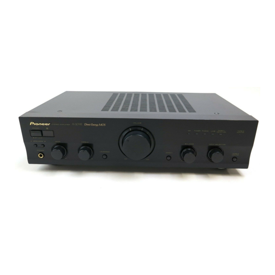
STEREO AMPLIFIER
A-209R
A-209
THIS MANUAL IS APPLICABLE TO THE FOLLOWING MODEL(S) AND TYPE(S).
Model
Type
A-209R
MYXJ
MVXJ
MLXJ
–
SBDXJ
–
CONTENTS
1. SAFETY INFORMATION ...................................... 2
2. EXPLODED VIEWS AND PARTS LIST ............... 3
4. PCB CONNECTION DIAGRAM ......................... 16
5. PCB PARTS LIST ............................................... 24
6. ADJUSTMENT .................................................... 27
PIONEER CORPORATION
PIONEER ELECTRONICS SERVICE, INC. P.O. Box 1760, Long Beach, CA 90801-1760, U.S.A.
PIONEER EUROPE N.V. Haven 1087, Keetberglaan 1, 9120 Melsele, Belgium
PIONEER ELECTRONICS ASIACENTRE PTE. LTD. 253 Alexandra Road, #04-01, Singapore 159936
c
PIONEER CORPORATION 2000
Î
POWER
—
_
OFF
ON
A SPEAKERS B
PHONES
Power Requirement
A-209
–
AC220-230V
–
AC220-230V
AC220-230V
AC110V/120-127V/220V/240V
4-1, Meguro 1-chome, Meguro-ku, Tokyo 153-8654, Japan
z¿<?/B Direct Energy MOS
VOLUME
STEREO AMPLIFIER
CD
TUNER
PHONO
BASS
TREBLE
BALANCE
LOUDNESS
DIRECT
–
+
–
+
L
R
MIN
MAX
The voltage can be converted by
the following method.
–––––
–––––
–––––
With the voltage selector
7. GENERAL INFORMATION ................................ 28
7.1 DISASSEMBLY ............................................ 28
7.2 IC .................................................................. 29
8. PANEL FACILITIES AND SPECIFICATIONS ....... 30
TAPE 1
TAPE 2
LINE
/CD-R/MD
MONITOR
INPUT SELECTOR
ORDER NO.
TAPE 2
MONITOR
RRV2283
T – ZZK APR. 2000 Printed in Japan
Advertisement
Table of Contents

Related Manuals for Pioneer A-209R


Summary of Contents for Pioneer A-209R
- Page 1 PIONEER CORPORATION 4-1, Meguro 1-chome, Meguro-ku, Tokyo 153-8654, Japan PIONEER ELECTRONICS SERVICE, INC. P.O. Box 1760, Long Beach, CA 90801-1760, U.S.A. PIONEER EUROPE N.V. Haven 1087, Keetberglaan 1, 9120 Melsele, Belgium PIONEER ELECTRONICS ASIACENTRE PTE. LTD. 253 Alexandra Road, #04-01, Singapore 159936 PIONEER CORPORATION 2000 T –...
-
Page 2: Safety Information
The use of a substitute replacement component which does Leakage 0.5mA current Device not have the same safety characteristics as the PIONEER tester under recommended replacement one, shown in the parts list in test this Service Manual, may create shock, fire, or other hazards. -
Page 3: Exploded Views And Parts List
See Contrast table(2) Power Cord with Fuse See Contrast table(2) Fuse (T5A) See Contrast table(2) (2) CONTRAST TABLE A-209R/MYXJ, MVXJ, A-209/MLXJ and SBDXJ are constructed the same except for the following : Part No. Mark Symbol and Description A-209R A-209R... - Page 4 A-209R, A-209 2.2 EXTERIOR SBDXJ Type Only MYXJ, MVXJ Types Only 28 or 44 MYXJ, MVXJ Types Only SBDXJ Type Only MLXJ, SBDXJ MYXJ, MVXJ...
- Page 5 AMR2533 Screw IBZ30P120FCC • • • • • Shield Plate See Contrast table(2) (2) CONTRAST TABLE A-209R/MYXJ, MVXJ, A-209/MLXJ and SBDXJ are constructed the same except for the following : Part No. Mark Symbol and Description A-209R A-209R A-209 A-209...
-
Page 6: Block Diagram And Schematic Diagram
A-209R, A-209 3. BLOCK DIAGRAM AND SCHEMATIC DIAGRAM 3.1 BLOCK DIAGRAM CN101 IC151 CN102 RIAA ON/OFF 2.8mV AF ASSY PHONO /50kΩ 37dB IC101 Q501 TUNER FUNCTION Q503 Q101 LOUDNESS CN203 CN501 200mV /50kΩ LINE VOLUME TAPE1 VR501 Q103 /CD-R 1, 2... - Page 7 A-209R, A-209 VOLUME ASSY AF ASSY DIRECT ENERGY MOS DIRECT ON/OFF POWER AMP WRLC 39dB PROTECTION RY Q505 CN501 CN203 RY401 SP-A RY402 IC301 SP-B Q507 Q509 Q309–Q330 RY403 Q303 J551 CN502 UNUSUAL OUTPUT J551 FUNC DETECTION MUTE JA501 Q331, Q327, Q328...
-
Page 8: Overall Connection Diagram
A-209R, A-209 3.2 OVERALL CONNECTION DIAGRAM FRONT R ASSY HEADPHONE ASSY AWX7124 (MYXJ, MVXJ) AWX7114 AWX7121 (MLXJ, SBDXJ) AF ASSY AWX7117 (MYXJ, MVXJ) AWX7116 (MLXJ, SBDXJ) VOLUME ASSY AWX7118 (MYXJ, MVXJ) AWX7112 (MLXJ, SBDXJ) - Page 9 A-209R, A-209 Note : When ordering service parts, be sure to refer to "EXPLODED VIEWS and PARTS LIST" or "PCB PARTS LIST". FRONT L ASSY AWX7123 (MYXJ, MVXJ) AWX7122 (MLXJ, SBDXJ) AC POWER CORD ADG1154 : MYXJ, MLXJ types AC PRIMARY ASSY...
- Page 10 A-209R, A-209 3.3 VOLUME and HEADPHONE ASSYS HEADPHONE ASSY AWX7114 J551A : AUDIO SIGNAL ROUTE VOLUME ASSY AWX7118 (MYXJ, MVXJ) AWX7112 (MLXJ, SBDXJ) ACX7038 VR-501 : ACX7038 (MYXJ, MVXJ) VR-501 : ACS7035 (MLXJ, SBDXJ) (MYXJ, MVXJ) CN203...
- Page 11 A-209R, A-209 3.4 AC PRIMARY ASSY • NOTE FOR FUSE REPLACEMENT CAUTION - FOR CONTINUED PROTECTION AGAINST RISK OF FIRE. REPLACE WITH SAME TYPE AND RATINGS ONLY. AC PRIMARY ASSY AWX7113 (MYXJ, MVXJ, MLXJ) AWX7670 (SBDXJ) MYXJ, MVXJ, MLXJ types...
- Page 12 A-209R, A-209 3.5 AF ASSY : AUDIO SIGNAL ROUTE AF ASSY AWX7117 (MYXJ, MVXJ) AWX7116 (MLXJ, SBDXJ) C313,C337 : IDLE ADJ. (L CH) C314,C338 : IDLE ADJ. (R CH) MYXJ, MVXJ ONLY MYXJ, MVXJ ONLY CN501...
- Page 13 A-209R, A-209 CAUTION : FOR CONTINUED PROTECTION AGAINST RISK OF FIRE. REPLACE ONLY WITH SAME TYPE NO. 491001 MFD, BY LITTELFUSE INK. FOR IC454 (AEK7009). ACH7080 C451 (6800/42) ACH7081 C452 IRF530(S) (6800/42) IRF9530(S) IRF530(S) IRF9530(S) Q333–Q336: J551 CN601...
- Page 14 A-209R, A-209 3.6 FRON L, FRONT R and OPT ASSYS FRONT L ASSY OPT ASSY AWX7123 (MYXJ, MVXJ) AWX7125 AWX7122 (MLXJ, SBDXJ) (MYXJ, MVXJ) MYXJ, MVXJ ONLY FRONT L ASSY S702 : LOUDNESS S703 : SPEAKER A S704 : SPEAKER B...
- Page 15 A-209R, A-209 FRONT R ASSY AWX7124 (MYXJ, MVXJ) MYXJ, MVXJ ONLY AWX7121 (MLXJ, SBDXJ) MYXJ, MVXJ ONLY VSG1009 VSG1009 INPUT SELECTOR MYXJ, MVXJ ONLY FRONT R ASSY S601 : INPUT SELECTOR TUNER PHONE LINE TAPE1/CD-R/MD S602 : DIRECT S603 : TAPE2 MONITOR...
-
Page 16: Pcb Connection Diagram
A-209R, A-209 4. PCB CONNECTION DIAGRAM 4.1 VOLUME ASSY NOTE FOR PCB DIAGRAMS : 1. Part numbers in PCB diagrams match those in the schematic 3. The parts mounted on this PCB include all necessary parts for diagrams. several destinations. - Page 17 A-209R, A-209 4.2 HEADPHONE and AC PRIMARY ASSYS HEADPHONE ASSY HEADPHONE ASSY (ANP7232-A) (ANP7232-A) J551A SIDE A SIDE B AC PRIMARY ASSY POWER TRANSFORMER VOLTAGE SELECTOR (SBDXJ Type) SIDE A AC POWER CORD (ANP7232-A) AC PRIMARY ASSY SIDE B (ANP7232-A)
- Page 18 A-209R, A-209 4.3 AF ASSY AF ASSY POWER TRANSFORMER...
- Page 19 A-209R, A-209 SIDE A Q153 Q341 IC101 IC451-IC453 CN601 Q333-Q336 Q324,Q326 VR302 Q452 IC301 CN501 Q451 VR301 Q323,Q325 IC454 J551 (ANP7232-A)
- Page 20 A-209R, A-209 AF ASSY...
- Page 21 A-209R, A-209 SIDE B Q151 IC151 Q152 Q338,Q337 Q340,Q339 Q102 Q101 Q104 Q103 Q332 Q328,Q327 Q318,Q330 Q322,Q320 Q316,Q314 Q312,Q310 Q304,Q303 Q311,Q309 Q315,Q313 Q321,Q319 Q317,Q329 Q331,Q343 (ANP7232-A)
- Page 22 A-209R, A-209 4.4 FRONT L ASSY FRONT L ASSY J603A CN502 J602 VR751 VR752 Q707 Q708 (ANP7231-A) SIDE A FRONT L ASSY IC751,Q701 Q703,Q702 Q705,Q704 (ANP7231-A) SIDE B...
- Page 23 A-209R, A-209 4.5 FRONT R and OPT ASSYS FRONT R ASSY IC601 VR601 (ANP7231-A) CN202 J602A SIDE A FRONT R ASSY Q608-Q613 Q614-Q616 Q601-Q606 (ANP7231-A) SIDE B OPT ASSY OPT ASSY J603 (ANP7231-A) (ANP7231-A) SIDE A SIDE B...
-
Page 24: Pcb Parts List
A-209R, A-209 Mark No. Description Part No. Mark No. Description Part No. 5. PCB PARTS LIST • NOTES: Parts marked by "NSP" are generally unavailable because they are not in our Master Spare Parts List. • mark found on some component parts indicates the importance of the safety factor of the part. - Page 25 A-209R, A-209 Mark No. Description Part No. Mark No. Description Part No. D461 S5566G(TPB2) CAPACITORS D311,D312 UDZ15B C801,C802 (0.01µF/AC250V) ACG7020 D457,D458 UDZ36B D456 UDZ4.7B OTHERS D341 UDZS5.1B CN801 AC INLET AKP7005 D462 UDZS5.6B H1,H2 FUSE CLIP AKR7001 RELAYS AF ASSY...
- Page 26 A-209R, A-209 Mark No. Description Part No. Mark No. Description Part No. R461-R463 RS1LMF390J OTHERS R403 RS1LMF821J 3P CABLE HOLDER 51063-0305 R373-R376 RS1LMFR22J 7P CABLE HOLDER 51063-0705 VR301,VR302 (2.2kΩ) VCP1123 13P CABLE HOLDER 51063-1305 Other Resistors RS1/10S J603 JUMPER WIRE...
-
Page 27: Adjustment
A-209R, A-209 6. ADJUSTMENT 6.1 IDLE CURRENT ADJUSTMENT ¶ CAUTION : Heatsinks’ (Q323–Q326) DC level is equal to +B or -B. Don’t touch them or you will be electric shocked. 1. Connect the measuring instrument as shown in Fig.6-1. (R373 or R374) 2. -
Page 28: General Information
A-209R, A-209 7. GENERAL INFORMATION 7.1 DISASSEMBLY ×2 ×2 Front Panel Diagnose the AF Assy. ∗ : Be careful not to injure ×2 the Front Panel. ×5 Rear Panel Chassis Unhook lead wires. Rear Panel Service Chassis ×3 Screw for Rear Panel ×2... - Page 29 A-209R, A-209 7.2 IC 7 PD5443A (FRONT R ASSY : IC601) • The information shown in the list is basic information and ¶ ¶ ¶ ¶ ¶ REMOTE CONTROL AMP MICROCOMPUTER may not correspond exactly to that shown in the schematic ¶...
-
Page 30: Panel Facilities And Specifications
DIRECT TAPE 2 MONITOR – – The illustration shows the A-209R. TAPE 2 MONITOR button/indicator POWER (— OFF/_ ON) switch Press to turn power to the unit ON and OFF. Use when there is an adaptor component (graphic equalizer, This unit cannot be turned ON and OFF using the remote etc.) or cassette deck connected to the TAPE2 MONITOR... - Page 31 A-209R, A-209 DIRECT button/indicator BASS tone control Use this button when you do not wish to pass the output from Use to adjust the low-frequency tone. The center position is the input terminal equipment through the various frequency ad- flat (normal) position. When turned to the right, low-frequency justing circuits (BASS, TREBLE, BALANCE, LOUDNESS).
-
Page 32: Rear Panel
This jack is for output of control signals when operating other components bearing the Î mark with the attached remote TAPE 1/CD-R/MD REC (OUT) terminals control unit. (on the A-209R only) TAPE 1/CD-R/MD PLAY (IN) terminals AC INLET jack Connect power cord to here and an AC wall socket, or the AC TAPE 2 MONITOR REC (OUT) terminals outlet of an audio timer. - Page 33 NOTE: connected to TAPE 2 MONITOR terminals. When the accessory remote control unit is used to operate other Pioneer components with the Î mark, it cannot be used LINE : For playback with a component connected to the LINE terminal.
-
Page 34: Sbdxj
8.2 SPECIFICATIONS Power requirements ....AC 220 – 230 V, 50/60 Hz Amplifier Section Power consumption [A-209R] ..............130 W Continuous power output Dimensions (including knobs and other protruding parts) (both channels driven at 20 Hz to 20 kHz)** ........420 (W) x 114 (H) x 307 (D) mm [A-209R] T.H.D.
Need help?
Do you have a question about the A-209R and is the answer not in the manual?
Questions and answers