
Related Manuals for PowerMaster PM-SBC-2012

Summary of Contents for PowerMaster PM-SBC-2012
-
Page 1: User Manual
SWITCH-MODE BATTERY CHARGER (MICROPROCESSOR SYSTEM) USER MANUAL FOR ALL PATTERNS 1 AND 3 OUTPUTS... -
Page 2: Table Of Contents
CONTENTS Introduction......................2 Technical Features ....................2 Advanced Charging Technique ................3 Safety Devices......................3 Options........................4 Safety Instruction....................4 Installation......................5 Front Panel ......................7 LED Indicators....................... 7 Switches Section (4 Battery Types and 1 User Define) ........7 Instruction of Charging Curve Selection ............. -
Page 3: Introduction
Introduction Power Master Battery Charger is small and lightweight charger that offers charging patterns which are perfectly adapted to each battery technology (liquid electrolyte, gel electrolyte, lead calcium, etc... ). A charging pattern may be factory set to suit your specific application. -
Page 4: Advanced Charging Technique
Advanced Charging Technique Charging curves of the 3-state IUU type, with a boost phase and a floating phase. The 3-state charging characteristic, used on boats everywhere, saves on charging time. In addition, the charger can be adapted to all types of battery thanks to its 5 integral charging curves supervised by a micro controller. -
Page 5: Options
Disjonction protection against: - Battery overvoltage or undervoltage - Battery or charger overtemperature Protection by fuses against : - Mains input overload - Battery polarity inversion Anti-corrosion Casing in aluminum with anti-corrosion paint. Anti-impact Resistance to impacts in normal use thanks to the 2 mm-thick casing (1,5mm for the cover). -
Page 6: Installation
Master Charger delivers the current necessary for battery charge and adapts itself to supply the optimum end of charge. The accidental and violent overcharge or higher end of charge current produces early destruction by excessive rise of temperature. The temperature should not exceed 50°C. By the regulation of the current, the Power Master protects the battery from the temperature rise at the end of charge. - Page 7 2. Connect the negative battery cable to terminal marker –BAT and open the entry of the upper case to tighten it with screws. 3. Do the same for batteries number 2 and 3 for +BTA 2 and +BTA 3. For a 3 outputs charger, refer to the table below to choose conductor section.
-
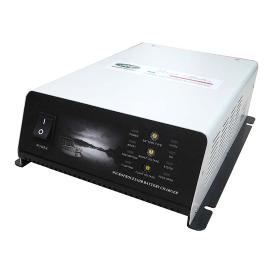
Page 8: Front Panel
Front Panel 15A/24V, 20A/12V 30A/24V, 40A/12V, 50A/24V, 60A/12V LED Indicators POWER: It is lit when the AC power has been input through the AC plug. BOOST: It is lit as long as the battery is not fully charged at set voltage. ABSORPTION: It is lit as long as the battery is not fully charged at set voltage. -
Page 9: Switches Section (4 Battery Types And 1 User Define)
Fuse is broken. FUSE OPEN Switches Section (4 Battery Types and 1 User Define) The great advances realized by manufacturers of batteries put at the disposal of users batteries without maintenance, so it means a certain tranquillity for the user but impose, however on the charger system, an exacting precision. -
Page 10: Dc Power Supply
BOOST VOLTAGE Selection Rotate Boost Rotate Boost Rotate Boost Rotate Boost Switch Volt. Switch Volt. Switch Volt. Switch Volt. 14.4V 14.9V 15.4V 14.3V 14.5V 15.0V 15.6V 14.6V 15.1V 15.8V 14.7V 15.2V 16.0V 14.8V 15.3V 14.2V FLOAT VOLTAGE Selection Rotate Switch Floating Volt. -
Page 11: Bts/Remote Control
0.2V 0.7V 0.3V 0.8V 0.4V 0.9V Example: To set the desired DC power supply of 14.3V, firstly, choose the rotate switch of battery type to be“0"and then choose the rotate switch of boost voltage to be“1"; finally, choose the rotate switch of float voltage to be“3". BTS/Remote Control It is a port for phone jack of the battery temperature sensor and upcoming remote control to be connected. - Page 12 The charger is near to the Ventilate the charger "switch off" temperature Red LED DEFAULT Battery temperature is too Check the charging curve flashes high (with a temperature and placed the battery in a sensor) ventilated area Default of the battery which Check the connection of the All LEDS are flashing but is in deep discharged or...
-
Page 13: Specification
Specifications Output: 12V Model No. PM-SBC-2012 PM-SBC-4012F PM-SBC-6012F Input voltage Universal input: 230V ~ Input Voltage 90V to 250V +10%/-15% Output Voltage Charging Capacity 50Hz/60Hz Frequency 1 or 3 Output Patterns +/-2% Input Voltage U bat +/-10% Output Current I bat... - Page 14 Output: 24V Model No. PM-SBC-1524 PM-SBC-3024F PM-SBC-5024F Input voltage Universal input: 230V ~ Input Voltage 90V to 250V +10%/-15% Output Voltage Charging Capacity 50Hz/60Hz Frequency 1 or 3 Output Patterns +/-2% Input Voltage U bat +/-10% Output Current I bat 3 states IUU type Charging Curve Type (Boost Charge, Absorption Charge, Floating Charge)
Need help?
Do you have a question about the PM-SBC-2012 and is the answer not in the manual?
Questions and answers