Table of Contents
Advertisement
Quick Links
SPECIAL NOTE FOR EUROPEAN / CE
The owner's manual included with your
purchase refers to the US model of the
MultiMAX. The following adjustments or errata
should be noted for proper operation of your
European / CE MultiMAX:
Pages 10 and 50:
The CE MultiMAX now includes the
ACC port. The unit cannot be powered
from this port (differs from US units) but
other functions are enabled as they
become available
Page 18:
As of this printing, the CE MultiMAX is
additionally compatible with Profoto
Acute2R (CE version) flash generators.
The CE MultiMAX is not compatible with
the following products as these products
were not produced on CE frequencies:
10 Channel Classic, 16 Channel
Classic, PocketWizard MAX, and
Calumet TurboFilter.
MultiMAX CUSTOMERS
Advertisement
Table of Contents

Related Manuals for Pocket Wizard MultiMAX

Summary of Contents for Pocket Wizard MultiMAX
- Page 1 (differs from US units) but other functions are enabled as they become available Page 18: As of this printing, the CE MultiMAX is additionally compatible with Profoto Acute2R (CE version) flash generators. The CE MultiMAX is not compatible with...
- Page 2 PocketWizards on these frequencies. CE PocketWizard Radio Frequencies: Channel Frequency Unit Digital Code 433.62 Plus or 1 - 16 16 Bit MultiMAX 24 Bit 434.22 MultiMAX 17 - 32 (20 Bit in Only FAST MODE) Special Note Revision 1.00 (LPF205B)
- Page 3 Owner’s Manual www.PocketWizard.com...
- Page 5 It is the most innovative and advanced wireless solution in the photographic industry. As a stand-alone unit, the MultiMAX offers precision special effects functions not available in any wireless triggering device. It incorporates integrated...
-
Page 6: Table Of Contents
Triggering Multiple Flashes With Multiple RECEIVE Units ....16 Connecting MultiMAX (set for TRANSMIT mode) to Flash ... . . 16 Standard Radio Operation. - Page 7 True Confirmation ..........21 Radio .
- Page 8 Other Features ..........38 Keypad Lock .
-
Page 9: The Fcc Wants You To Know
This US frequency MultiMAX is compatible with all US frequency PocketWizard products. It is not frequency compatible with CE or JAPAN PocketWizard products. Verify frequency compatibility before purchasing. Some products are not manufactured on every frequency. Always operate within local radio regulations. -
Page 10: Icons Used In This Manual
ICons used In ThIs Manual Read the information following this icon. It shows important notes about the subject being discussed. ☞ Follow this icon for more detailed information on the subject in another section. Î Find valuable tips and techniques with this icon. Warning or caution. -
Page 11: Features
feaTures Communication Technology – Full Digital Radio Communication – Microprocessor controlled – 32 digitally coded channels – Complex 16 or 24 bit coded signal – Selective Quad-Triggering Basic Features – Built-in hot shoe – 1/4-20 female mounting thread – Built-In AC adapter jack (see Page 49 for ordering information) –... -
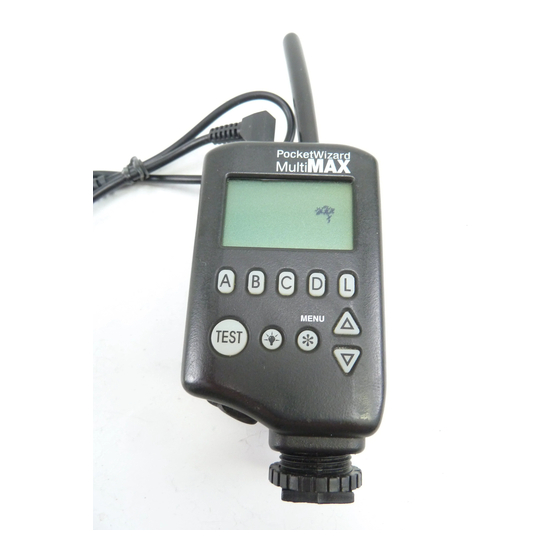
Page 12: Part Reference
MulTIMax ParT referenCe Battery Flexible Antenna Door Latch ¼ - 20 Tripod Mount Status Light PORT 2 Output PORT 1 Lanyard Input / Output Loop LCD (Liquid Crystal Display) USB Port Power / TRANSMIT / Battery RECEIVE Door Mode Switch... -
Page 13: Lcd Information
lCd InforMaTIon... -
Page 14: Controls
A B C D L = Selects Quad-Triggering Zones and Local. Also used in menu navigation and numeric entry • TEST = Triggers MultiMAX. Press to test operation or to trigger remote units and/or attached cameras/flashes • Illuminates LCD and keypad. Hold down for key lock. -
Page 15: Getting Started
CAUTION: Turn OFF your equipment (PocketWizard units, electronic flash units, cameras, etc.) before making connections or changing batteries. Install 2 fresh AA (IEC:LR6) batteries into the MultiMAX. Make sure to note proper polarity. Alkaline batteries are recommended. Rechargeable batteries will also work, though operation time may be reduced. -
Page 16: Battery Life
The unit will continue to function normally until the batteries are nearly exhausted. The MultiMAX voltage regulation is very efficient. There is only a small benefit when using Lithium batteries. Lithium batteries are designed for the quick burst high current draw found in cameras and portable flash devices. -
Page 17: Quick Setup - Basic Radio Slave Operation
(default is TRANSMIT = A B C D L, RECEIVE = A) 6. Turn camera and flash on 7. Press TEST button on MultiMAX (set for TRANSMIT mode) and release. Confirm remote flash triggers. You’re all set! Use the camera normally. -
Page 18: Triggering Multiple Flashes With Multiple Receive Units
Connecting MultiMAX (set for TRANSMIT mode) to Flash A flash can be connected to a MultiMAX (set for TRANSMIT mode). It will trigger in sync with the remote flash units. This flash is called the local flash and is usually mounted on a camera bracket. -
Page 19: Standard Radio Operation
Transceiver Control The MultiMAX operates as either a transmitter or a receiver. To use the MultiMAX as a Transmitter (sending device) set the power switch to TRANSMIT. To use the MultiMAX as a Receiver set the power switch to RECEIVE. -
Page 20: Compatibility
Nikon D1 series with PocketWizard Upgrade 1 – 16 1 – 32 Quad-Triggering The digital radio design of the MultiMAX will enable it to be fully compatible with future PocketWizard products. PocketWizard manufactures products for 3 different world frequencies: US, CE, and JAPAN. Not every PocketWizard manufactures products for 3 different world frequencies: US, CE, and JAPAN. -
Page 21: Selective Quad-Triggering (A B C D Keys)
A B C D This powerful feature is used to individually control up to 4 sets of MultiMAX units (set for RECEIVE mode) on the same channel. Each keypad letter, A B C D refers to an individual zone. Each zone can be independently selected or deselected from a MultiMAX (set for TRANSMIT mode). -
Page 22: Classic Channels
Operation on these channels is identical to the function of the LOCAL / BOTH / REMOTE switch found on PocketWizard Plus and Classic Transmitters. L Key = On any channel the L key toggles the local flash on or off in a MultiMAX (set for TRANSMIT mode). ☞... -
Page 23: True Confirmation
Optional Flash Confirmation Cable Using the flash confirmation cable the MultiMAX can confirm flash sync for all four zones on every trigger. 1. Attach flash confirmation cable to PORT 1 for each MultiMAX (set for RECEIVE mode) 2. - Page 24 A RECEIVE unit set to FAST MODE Confirms on zone A only A RECEIVE unit set to Intervalometer or Multipop Provides radio confirmation before the first interval only Note: Older MAX and MultiMAX units set to FAST MODE will not confirm on any zones.
-
Page 25: Menu System
Menu sysTeM Navigation Many functions of the MultiMAX are accessed through easy-to-navigate menus. Press /MENU to enter the menu system. Menu items are selected by using the A B C D L keys. You can also use the ▲▼ keys to highlight the menu item you want, then press /MENU to select. -
Page 26: Numeric Entry
D and L select the same digit. ☞ To perform a Lag Time Measurement, use Equalize Mode (see Page 34) which requires that the MultiMAX be set for RECEIVE. Î To quickly get to the lowest setting press and Example 2: Numeric Entry... -
Page 27: Main Menu
Î Go Normal is a quick way to get to standard radio slave operation after using advanced functions and menus. Use this function to “turn off” an advanced mode and use the MultiMAX as a radio slave only. -
Page 28: Basic Settings
Additional triggers occurring during contact time are ignored. Contact time is NOT the length of time a MultiMAX (set for TRANSMIT mode) will send a radio triggering signal. Contact time affects PORT 1 and PORT 2 only and does not affect radio trigger transmission. - Page 29 For triggering remote cameras, a longer contact time allows for continuous repeatable motor drive triggering (example: 5 frame bursts every trigger). It also allows for controlled bulb exposure. • Example of Burst Shooting: If a remote camera is capable of firing 3 frames per second in continuous motor drive, then a contact time of 1 second will always result in this remote camera triggering for 3 exposures •...
-
Page 30: B: Beep Menu
Any Key is pressed except TEST ☞ A MultiMAX (set for RECEIVE mode) set to Beep on Zero / Error or set to Beep on All will indicate a confirmation error if the unit is also set to count down and the counter reaches zero. -
Page 31: C: Lcd Contrast Adjustment
C: LCD Contrast Adjustment – /MENU B C Enters the LCD Contrast Adjustment screen. Use ▲▼ to adjust the contrast. Contrast can be affected by temperature. Setting the contrast to a middle setting is recommended for most situations. D: RESET - /MENU B D Resets the unit to factory defaults. -
Page 32: Counter Menu
CounTer Menu Press /MENU C enter the Counter Menu. This menu controls the counter functions of the MultiMAX. The counter can show the total number of triggers. Count is incremented on every trigger from any source: PORT 1, TEST button, Hot Shoe, or Radio Trigger. -
Page 33: Advanced Menu
Advanced Menu Advanced Menu A: Delay Menu – TRANSMITTER – /MENU A A Enters the delay menu for MultiMAX units (set for TRANSMIT mode). ☞ Delay menus, with the exception of Rear Curtain, require numeric entry. See the Numeric Entry section, Page 24. -
Page 34: B: Remotes Only
Enters the numeric entry screen. Delays the Radio remote units only. PORT 2 will trigger immediately. Remote units will trigger after the displayed delay. If the contact time for the MultiMAX (set for TRANSMIT mode) is longer than the delay, PORT 2 will remain contacted for the delay time rather than the contact time. -
Page 35: A: Delay Menu - Receiver
A: Delay Menu - RECEIVER – /MENU A A Enters the delay menu for a MultiMAX (set for RECEIVE mode). Each RECEIVE unit can have its own delay for sequences or for synchronization. To easily delay all RECEIVE units the same amount, use the Transmitter’s delay. -
Page 36: C: Equalize
This number is a calculated number and will differ from the lag time you saw on the previous screen 6. Repeat steps 1 through 5 for each camera to be equalized. Use one MultiMAX (set for RECEIVE mode) per camera. -
Page 37: B: Intervalometer (Time Lapse Photography)
For remote interval operation, use interval mode on a RECEIVE unit. Each MultiMAX (set for RECEIVE mode) may have a unique interval setting or can be used with equal settings. Interval and count entry screens are instantly active The Set Interval and Adjust Counter screens are instantly active. -
Page 38: C: Multipop
For delays longer than 9.9999 seconds (maximum available in delay modes) use Intervalometer or Multipop mode. Set the interval to the desired delay. Set the count to 1. Attach your camera to PORT 1 and trigger the MultiMAX . The camera will trigger after the set interval. -
Page 39: D: Speedcycler - Transmitter
Only the zone just triggered will display proper confirmation If L is selected then PORT 2 on the MultiMAX (set for TRANSMIT mode) will trigger every time and is not cycled. It will be in sync with each cycled zone. -
Page 40: D: Fast Mode - Receiver
A MultiMAX (set for RECEIVE mode) in fast mode will show FAST MODE on the display. While in this mode Quad-Triggering and Relay Mode are not available and the A B C D L keys perform no function on a RECEIVE unit. -
Page 41: Relay Mode
1. Set a MultiMAX to TRANSMIT mode and select the channel and zones for the remote flash units 2. Set the same MultiMAX to RECEIVE mode and select the channel and zone for the remote camera. Use a different channel then the remote flash units. -
Page 42: Applications Of Advanced Functions
1. Attach the camera’s PC terminal to PORT 1 on a MultiMAX (set for TRANSMIT mode) 2. Attach manual or Automatic flash to MultiMAX (set for RECEIVE mode) 3. On the MultiMAX (set for TRANSMIT mode) press /MENU A A B to enter the set delay screen 4. -
Page 43: Programmed Sequence Shooting
The corresponding shutter speed is the fastest speed you can safely use for this procedure 4. Set the delay time on the MultiMAX (set for TRANSMIT mode) to the same number as your on-camera flash unit’s longest flash duration... -
Page 44: Camera Equalization
This is not a flaw of either the camera or the MultiMAX. A varying lag time in a camera is considered acceptable operation for the majority of photographic situations. Cameras are usually designed to respond predictably shot to shot, but are not necessarily or specifically designed to do so with the precision needed for equalization. -
Page 45: Lag Time Measurement
Using the information above set up your camera for best equalization performance. Attach a MultiMAX (set for RECEIVE mode) to the camera as follows: 1. Place a MultiMAX in the camera’s hot shoe or attach a cable from the camera’s PC terminal to PORT 1 2. - Page 46 Î Speed is not the most important factor in camera equalization, consistency is. If a slow camera has extremely consistent lag times it will be a better equalization candidate than a faster but inconsistent camera. The reason why it is important to know the approximate fastest lag time for a camera, especially an inconsistent one, is to calculate margin of error (discussed later in this section).
- Page 47 If your camera’s maximum sync speed is slower than the number listed then you must use the slower sync speed. Camera equalization does not give a camera faster sync speeds than the camera is designed to handle. For all shutters it can be assumed that a camera with faster external flash sync speeds (X sync) will have faster shutter travel than cameras with slower X sync speeds.
-
Page 48: One Unit Equalization
6. Attach the slower camera’s motor drive to PORT 2 on the TRANSMIT unit. Do not leave the MultiMAX (set for TRANSMIT mode) in the hot shoe or have the PC terminal attached to PORT 1 as this may cause a looping or lock-up situation 7. - Page 49 If using both MultiMAX units as RECEIVE units being triggered by any PocketWizard Transmitter follow these steps: 1. Set both units to RECEIVE mode 2. Measure lag times of cameras as previously described and record the fastest lag for each 3.
-
Page 50: Equalization Adjustments
Equalization Adjustments With all the variable factors above it may seem that performing the math necessary for equalization is daunting. Here are some techniques for fine- tuning or adjusting equalization times without using specific math: On some 35mm cameras you can gauge timing without using film. If your camera allows triggering with the film back open you can verify synchronization visually. -
Page 51: Technical Information
TeChnICal InforMaTIon Specifications Weight: 5.4 ounces with alkaline batteries Dimensions: 1.4 inches deep x 2.1 inches wide x 4.0 inches tall (body only) Flexible antenna = 2.4 inches tall. 0.3 inches in diameter Batteries: 2 x AA (IEC:LR6), 1.5 V batteries, alkaline recommended Read the Getting Started section, Page 13, for more information ACC (Accessory Port): For AC Power use PW-AC-MX adapter Input / Output Ports:... -
Page 52: Radio Information
Bandwidth: Narrowband, 70KHz TRANSMIT, 230KHz RECEIVE PocketWizard Radio Frequencies: Channel Frequency Unit Digital Code 1 through 16 344.04 MHz Classic, Plus, MAX, 16 Bit and MultiMAX 346.50 MHz 347.00 MHz 347.50 MHz 348.00 MHz 348.50 MHz 349.00 MHz 349.50 MHz 24 Bit 350.00 MHz... -
Page 53: Maximum And Minimum Settings
Maximum and Minimum Settings The following table details the maximum and minimum values allowed for each numeric entry setting available in the MultiMAX. Setting Maximum Minimum Contact Time 999.99 seconds or .01 seconds 16 minutes, 39.99 seconds Delay Time 9.9999 seconds .0001 seconds (add 0.0005 to... -
Page 54: Troubleshooting
TroubleshooTInG When in doubt ! Many issues can be resolved by powering the unit off and then back on again or by resetting to factory default settings. Before proceeding to any other troubleshooting procedure follow these steps: 1. Set power to OFF 2. -
Page 55: Sustaining High Performance
PerforManCe Long distance performance from your Positioning Positioning MultiMAX depends on the orientation and position of the units. Whenever possible, try to maintain a line of sight between the units and keep the Best Best Acceptable Acceptable Poor... -
Page 56: Time Conversion Charts
TIMe ConversIon CharTs Fractions to Decimal: Here are some common photographic fractions in decimal values. All numbers are rounded to the nearest .0001 or 1/10,000th. ☞ These times are not Rear Curtain Sync times. These are precision numbers. Rear Curtain Sync numbers are always less than the exact conversions. Refer to the Rear Curtain section, Page 32, for more information. - Page 58 For more information about using your PocketWizard product visit: www.PocketWizard.com MultiMAX, USB version, Manual Change Revision 1.3 (LPF100)
Need help?
Do you have a question about the MultiMAX and is the answer not in the manual?
Questions and answers