Table of Contents
Advertisement
Electronics Co., Ltd.
Head office: 814, Pei-Kang Road, Chiayi, 600, Taiwan.
Taipei office: 5, Lane 118, Sung-teh Road, 100, Taipei, Taiwan.
Web-http: //www.mipro.com.tw
E-mail:
mipro
@mipro.com.tw
0681
0197
2CE129
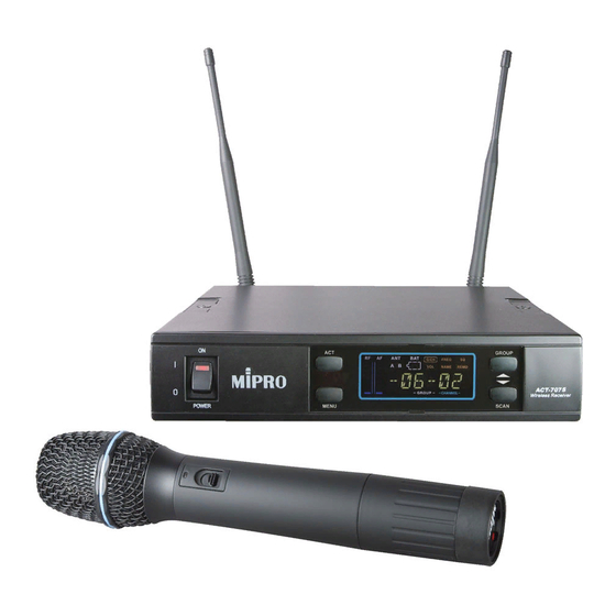
ACT-707S
Single
Channel Wireless Receiver
ACT-707S Single Channel Wireless Receiver
Instruction Manual
Z
1/2-rack Frame
Z
ACT-function
Z
Color LCD Panel
Z
100 Preset Channels
Advertisement
Table of Contents

Related Manuals for MIRPO ACT-707S


Summary of Contents for MIRPO ACT-707S
- Page 1 ACT-707S Single Channel Wireless Receiver ACT-707S Single Channel Wireless Receiver Instruction Manual 1/2-rack Frame ACT-function Color LCD Panel 100 Preset Channels Electronics Co., Ltd. 0681 Head office: 814, Pei-Kang Road, Chiayi, 600, Taiwan. 0197 Taipei office: 5, Lane 118, Sung-teh Road, 100, Taipei, Taiwan.
-
Page 2: Table Of Contents
Please read this manual thoroughly for correct operating and optimal performance. 3. INSTALLATION OF THE RECEIVER ACT-707S is a compact 1/2-rack, true diversity metal receiver. It features the world's first ACT-function and a color LCD panel displaying multiple 4. RECEIVER OPERATING PROCEDURES statuses. -
Page 3: Parts Name And Functions
ACT SINGLE CHANNEL WIRELESS RECEIVER ACT SINGLE CHANNEL WIRELESS RECEIVER 2. PARTS NAME AND FUNCTIONS Rear Panel¡G Front Panel¡G A N T GROUP G/CH F R E Q NAME REMO M H z MENU SCAN (Fig.2) (Fig.1) (5) Rear Antenna B input Connector: B Antenna connector can be installed with antenna directly and provides power for antenna booster. -
Page 4: Installation Of The Receiver
ACT SINGLE CHANNEL WIRELESS RECEIVER ACT SINGLE CHANNEL WIRELESS RECEIVER 3. INSTALLATION OF THE RECEIVER (c) Balanced Output: Using audio output cables attached with "XLR" or "Cannon" type, connect one end from the balanced output jacks (6) of the receiver, and the other end to the "MIC IN" input jack of the mixer or amplifier, as shown in Fig. -
Page 5: 2-Inch Units Receiver Installation
ACT SINGLE CHANNEL WIRELESS RECEIVER ACT SINGLE CHANNEL WIRELESS RECEIVER 5. 19/2-INCH UNITS RECEIVER INSTALLATION On the front panel of the receiver, 4 openings are pre-drilled for instant installation on the standard 19-inch rack case. (Shows in figure 7) 1. Single half-rack receiver To ensure best reception possible, receiver must be installed at least one Æ¡... -
Page 6: Operation Of Receiver With Lcd Display Panel
ACT SINGLE CHANNEL WIRELESS RECEIVER ACT SINGLE CHANNEL WIRELESS RECEIVER 7. Operation of Receiver with LCD Display Panel B. Operating explanation of setting Group: A. Press "MENU" button once, select "G/CH" block from the below line of LCD view wheredisplays a horizontal bar and two numbers that represents group & channel 1. - Page 7 ACT SINGLE CHANNEL WIRELESS RECEIVER ACT SINGLE CHANNEL WIRELESS RECEIVER A. Operating Procedures. (2) FREQ: Indicates the frequency that is currently inuse. MENU MENU EXIT GROUP A C T Save DOWN B. How to Operate? M E N U SCAN a.
- Page 8 ACT SINGLE CHANNEL WIRELESS RECEIVER ACT SINGLE CHANNEL WIRELESS RECEIVER (5) NAME: Indicates or setups the name of current channel user. Operation of ACT Feature: GROUP GROUP M E N U SCAN MENU SCAN A. Operating Procedures. A. Operating Procedures. MENU MENU NAME...
-
Page 9: Handheld Wireless Microphone
HANDHELD WIRELESS MICROPHONE HANDHELD WIRELESS MICROPHONE 2. BATTERY INSERTION 1. PARTS NAME AND FUNCTIONS (Fig.2) Unscrew battery cap in a counter-clockwise direction (7). Insert a 9V battery into the battery compartment according to the correct (Fig.1) polarity as shown in Fig.2. The moment the battery touches the terminals, the indicator will flash briefly (7). -
Page 10: Belt Pack Transmitter
BELT PACK TRANSMITTER BELT PACK TRANSMITTER 1. PARTS NAME AND FUNCTIONS 9. Battery Compartment and Cover:Accommodates two 1.5V(AA) batteries. 10.Detachable Belt Clip: Allows 360 degrees rotating to suit transmitting angles. To detach simply use a screwdriver at a 45 degree angle to unfasten. see diagram. -
Page 11: Af 4-Pin Input Connection Methods
BELT PACK TRANSMITTER BELT PACK TRANSMITTER 3. AF 4-PIN INPUT CONNECTION METHODS 4. BATTERY INSTALLATION 1. Pushing down both snap locks on the sides of battery cover to open battery (1) 2-Wire Electret condenser microphone Capsule cover. Take out the batteries. Fig.(3). 2.
Need help?
Do you have a question about the ACT-707S and is the answer not in the manual?
Questions and answers