Table of Contents
Advertisement
Quick Links
Advertisement
Table of Contents

Related Manuals for MIRPO MR-515


Summary of Contents for MIRPO MR-515
- Page 1 MR-515 Half 19-inch unit wireless receiver system Instruction Manual Electronics Co., Ltd. Head office: 814, Pei-Kang Road, Chiayi, 600, Taiwan. Taipei office: 5, Lane 118, Sung-teh Road, 110, Taipei, Taiwan. Web-http: //www.mipro.com.tw E-mail: mipro @mipro.com.tw 2CE095 ELECTRONICS CO.,LTD.
-
Page 2: Wireless Receiver
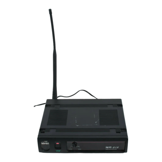
WIRELESS RECEIVER B. Rear Panel MIPRO Thank you for selecting half 19-inch unit non-diversity wireless receiver system. Before operating please read this instruction AFOUTPUT LEVEL A N T Antenna in rear manual carefully and thoroughly i n order to attain the correct operating procedures and achieve the best results. -
Page 3: Installation Of The Receiver
2. Installation of the receiver 3. Two 19/2-inch units receiver installation Single half-rack receiver (a) Push therack mount ear optional accessory (FB-11) upwardsuntil it is firmly attached to the receiver.(fig. 4) AFOUTPUT LEVEL A U X POWER (Fig.3) Install antenna in rear (1) or atthefront (9). Extend antenna to the POWER fullest position. - Page 4 Make sure that the system performs correctly by placing thesystem Under normal circumstances, the SIGNAL indicator lights up when a away from noise sources. Place the r eceiver at least 1 meter above microphone or transmitter is turned onnear the receiver to indicate the ground and away f rom noise sources.
-
Page 5: Handheld Wireless Microphone
HANDHELD WIRELESS MICROPHONE Plug the cable of the mains unit into dc socket on t he receiver's back panel. T hread t he cable through the c able grip as shown on the above illustration. The cable grip prevents t he connector from being pulled Microphone is modular design. -
Page 6: Battery Insertion
Belt Pack Transmitter 1. Battery Insertion 1. Parts Name and Functions (PHONE JACK) ( 4 PIN JACK) (Fig.2) Unscrew batterycap in counter-clockwise direction (6). Insert a 9V battery into the battery compartment according to the correct polarity as shown in Fig.2. The moment the battery touches the terminals o f compartment, the indicator will flash briefly (3). - Page 7 9. PowerSwitch:Switchto ONposition for operation. Switch to OFF position 4-Pin Jack: Align and insert theplug to jack accordingly andtighten whennot in use. it in the clockwise direction as shown in figure 4. 10. Battery Compartment and Cover: Accommodatesone piece 9V battery. 11.
-
Page 8: Af 4-Pin Input Connection Methods
3. AF 4-Pin Input Connection Methods (1) 2-Wire Electret condenser microphone Capsule SHIELD AUDIO 4PIN PLUG (2) 3-Wire Electret condenser microphone Capsule SHIELD AUDIO 4PIN BIAS PLUG (3) Dynamic Microphone SHIELD AUDIO 4PIN PLUG (4) Electric G uitar SHIELD AUDIO 4PIN PLUG Ω...
Need help?
Do you have a question about the MR-515 and is the answer not in the manual?
Questions and answers