Table of Contents
Advertisement
Advertisement
Table of Contents

Related Manuals for TC Electronic System 6000


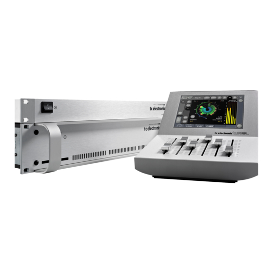
Summary of Contents for TC Electronic System 6000
- Page 2 IMPORTANT SAFETY INSTRUCTIONS The lightning flash with an arrowhead symbol within an The exclamation point within an equilateral triangle is equilateral triangle, is intended to alert the user to the intended to alert the user to the presence of important presence of uninsulated "dangerous voltage"...
-
Page 3: Table Of Contents
TC Icon Elements ..... . .6 System 6000 in a network ....31 Getting Sound . -
Page 4: Getting Started
• Power up both The Remote CPU and the Mainframe. A Basic System 6000 consists of a Mainframe, a Remote • The TC Icon Setup page appears. CPU and TC Icon and this type of setup is the basis for this •... -
Page 5: Icon Appearance
Structure Any parameter value can be adjusted in two accuracies. The core element of System 6000 is the 4 Engine A Normal and a Fine Adjust - mode. To switch between the structure. This structure enables you to run up to four two modes press the Value Fields above the faders. -
Page 6: Tc Icon Elements
TC Icon. Frame - Routing Faders at bottom The Routing page is the patch-bay of the System 6000 Mainframe. All routings of physical Inputs/Outputs as well as internal routing between the Engines are setup here. Fader at right side The understanding of this page is therefore essential to operating the System 6000. -
Page 7: Recall Operations
• Now select the level of: Scene, Routing or Engine 1-4. types available in System 6000. • Select which bank you wish to recall from: Factory or User. If a System 6000 formatted PCMCIA card is To access the Recall functions press: inserted in the Mainframe card-banks will be available Library (top tab), Recall (side tab) and Scene, Routing or and displayed below the User banks. -
Page 8: The Recall Wizard & Algorithm Filter
The Wizard To easily find the perfect preset for your application among the vast amount of presets available in the System 6000, we have added a Search-Wizard function. Basically the Wizard allows you to set up a few criteria and thereby narrow down the pool of presets to select from. - Page 9 THE WIZARD & ALGORITHM FILTER Type Algorithm Filter This is where you make the most detailed selection of presets to choose from. • Specify from which types of presets you would like to recall. Types vary depending on the selected Wizard Category selected on the Mode page.
-
Page 10: Store Operations
LIBRARY - STORE Operation Level Tabs Library, Frame and Engine selectors Function Select Press to add Tabs Wizard tags to presets. Fader Group Selector Parameter Fader values present in the last modified Engine. Library Store Fader assignments in the bottom of the display will always reflect the last modified Engine. -
Page 11: Bank Handling
BANK COPY - NAMING DISPLAY - DELETING PRESETS Library - Bank Naming Presets Via the Library Archive page you can copy Scene, All user preset types - Scene, Routing or Engine level Routing and Engine banks to and from a 3.5” disk or a can be renamed. -
Page 12: Frame
Introduction Internal overload LEDs and Reset Clip key The Routing page is the patch-bay of the System 6000 Each Engine is is constantly monitored for internal Mainframe. All routings of physical Inputs/Outputs as well overload. -
Page 13: Clock
FRAME - SYSTEM - MAIN Frame - E1 to E4 Clock Master Select the Clock source for the complete Mainframe, including all Engines and all I/O’s. Select between: Internal, Wordclock, AES 1-2, 3-4, 5-6 or 7-8. A lock up to an external source will take approx. 7 sec. It is not necessary to have the Physical Input routed to an Engine Input to have the clock accepted. -
Page 14: Smpte
Bank selection is done via Ctrl 0 (MSB) and Ctrl 32 (LSB): Reader Enabled On/Off switch for the System 6000 SMPTE Reader. • Controller 0 must be set to 0 in all cases. Frame Rate • Controller 32 value must match the bank number you Range: 24 FPS, 25 FPS, 29.97 FPS,... - Page 15 FRAME - SYSTEM - MAIN MIDI Control Page On MIDI Control Page the following options are available: Read Program Change Select whether the Frame should read incoming program changes or not. Send Program Change Select whether the Frame should send program changes to MIDI out when presets are recalled via TC Icon.
-
Page 16: External Midi Control
For most applications this will be quite fine and this is also the precision most external controllers and especially sequencers support. This is called 7 bit precision. However, System 6000 supports the 14 bit precision standard that has a considerably higher resolution: 128x128=16384 steps. - Page 17 Icon Faders to record automation into your sequencer: and set up the Send/Receive parameters as follows: Make sure that the record enabled MIDI track does not echo back the MIDI Input to the System 6000. Otherwise Send CC : OFF...
-
Page 18: Net
FRAME SYSTEM MAIN Error Indication If “no Lock” is acheived or “Sample Slip” situations occur Software versions this will be indicated via the small red dot in top of the Current installed software versions. Frame Tab. Press the Frame Tab and you will be guided to the exact Network Identifier page where you can correct or compensate for these Press the field “Network Identifier”... -
Page 19: Setup
FRAME - SYSTEM - I/O I/O - DSP Via the I/O page the following operations are handled: • Settings for the DSP card • Settings for up to three I/O cards • Labeling of all physical Input and Output channels Basic operation If more than one mainframe is connected: •... -
Page 20: Slot A, B & C
FRAME - SYSTEM - I/O I/O - Slot A, B & C Output, pin 2 selected Pin 2 hot, pin 3 connected to reference (shield) at the Input This is where you setup card specific parameters. of downstream device. In this mode pin 3 acts as a Parameters are only available when a I/O Card is detected. -
Page 21: Filters On Ada 24/96
With an AES-8 card installed in a Mainframe, you must select whether Input channels 9 through 16 should be digital or analog. The System 6000 holds numerous algorithms as a part of the standard package. Various additional algorithms are When Digital Input is selected: available. -
Page 22: Engine Edit
ENGINE - EDIT PAGE Name of the currently Library Frame and Engine Selectors recalled preset Display function Input indicator Meters Parameter Pages Link key Fader Output Group Meters Selector Fader Group Fine Adjust Parameters/ Mode Value fields The Engine 1-4 Edit Pages Bypass The Bypass key will respond in different ways depending This is where you edit algorithm parameters.Parameters in... -
Page 23: User Interface Settings
ICON SETUP Icon User Interface Sticky Clip Meter Clip Indicators Go to the Select & Setup pages pressing the TC Icon If the Sticky Clip function is activated the Internal Overload key in the upper left corner. LED on the Frame Routing page will stay lit once activated Press SETUP (upper tab) and UI (side tab) to enter the until Reset Clip on the Frame Routing page is pressed. -
Page 24: Auto Edit Page
SMPTE Auto Edit Page Cursor The triangular cursor always indicates the current clock position in relation to the Event List. Event Parameters For each Event the following parameters are available. Time - indicates the SMPTE time at which the Event takes place. -
Page 25: File
SMPTE Remote device disk drive Device This parameter selects which Mainframe connected to the Event lists can easily be organized and saved to a Floppy LAN you are working on. Device numbers 1-8, corresponds disk in the Mainframe. to the Device position at the Select page. Mainframe selection is done in the Auto Edit page. -
Page 26: Front & Rear
Slots must be filled consecutively in alphabetic order. Ground Lift The System 6000 DSP card fits the DSP slot only. When Use this standard chassis ground lift if you encounter I/O cards are mounted, dip switches on the cards must be problems with hum. -
Page 27: Cpu Front & Rear
REMOTE CPU - FRONT/REAR PANEL Remote CPU front panel POWER REMOTE CPU/SYSTEM 6000 POWER ON Power Key Power On LED Switches power On/Off. The LED will turn green when power is on. Remote CPU rear panel Ethernet/LAN Connection connection for TC Icon... -
Page 28: Updating Software
(Local Area Network). remove the floppy-disk. To setup your system 6000 in a network and update via LAN, please refer to the following pages. While uploading software, the power LED will flash It is not possible to update the Mainframe-software via between green and orange. -
Page 29: System 6000 In A Lan - Local Area Network
TCP/IP address The TCP/IP address is unique to each unit connected in If your setup is a standard System 6000 with a the network. Two units must therefore never have the same Mainframe and a TC Icon and no other units IP address. - Page 30 SETTING SUBNET MASK AND TCP/IP Setting the Subnet Mask of the Mainframe 6000 via the TC Icon • Go to the Setup Select pages. • Select the Main Frame on which you wish to change Subnet Mask. • Press Subnet Mask key and type in the desired Subnet Mask.
-
Page 31: System 6000 In A Network
This section is merely to illustrate how several System 6000 frames/TC Icons can be hooked up in a network. When more than one System 6000 mainframe or TC Icons are connected a 100 MB HUB or switch must be used. -
Page 32: Installing The Tc Icon Software Editor
TC Icon Remote for If during the process described above you have discovered the System 6000. The software is free to download for that the required MS Installer program is NOT already on evaluation BUT to actually operate a System 6000 via... - Page 33 MISCELLANEOUS The Complete manual Following additional information can be found in the complete English manual: • Detailed description of the System 6000 Algorithms • Technical specifications • In Depth information...
Need help?
Do you have a question about the System 6000 and is the answer not in the manual?
Questions and answers