Table of Contents
Advertisement
Advertisement
Table of Contents

Related Manuals for DeDietrich M 300 S

Summary of Contents for DeDietrich M 300 S
- Page 1 English Fuel oil burner M 300 S Installation instructions 300003201-001 - F...
- Page 2 Royal Decree dated 17/07/2009: Type of product Fuel oil burner Model M 300 S Applied standards - Royal Decree dated 17/07/2009 - BImSchV 2010 - Standard EN 267 - 2006/95/EC Low Voltage Directive Reference Standard: EN 60.335...
-
Page 3: Table Of Contents
1 Recommended Settings M 301 S.................................20 2 Recommended Settings M 302 S.................................22 Checking the operation............................24 Final checks ................................24 Maintenance procedure ............................24 Electrical diagram..............................25 Operating incidents ..............................27 Spare parts - M 300 S - 300003201-002-F......................28 M 300 S 11/2010 - 300003201-001 - F... -
Page 4: Security Measures
Risk of injury and damage to equipment. Attention must be paid to the warnings on safety of persons and equipment. Specific information. Information must be kept in mind to maintain comfort. Assembly stage Markers 11/2010 - 300003201-001- F M 300 S... -
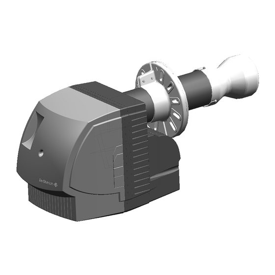
Page 5: Burner Description
Insulation class : IP 21 Envisaged use M 300 S range burners are designed to specifically operate with "hot water furnaces" for heating premises and domestic hot water. Please contact us for other applications, industrial processes and specific applications. Check for optimal compatibility with the burner equipment / furnace / flue in order to guarantee a low pollution operation. The layout and size of the flue shall be in accordance with the existing directives and regulations. -
Page 6: Dimensions
M 301-2 S / M 302-2 S min. 130 M 301-3 S / M 302-3 S min. 130 M 301-4 S / M 302-4 S min. 130 M 302-5 S min. 130 M 302-6 S min. 130 11/2010 - 300003201-001- F M 300 S... -
Page 7: Technical Data
**Separate power supply (See Electrical diagram). Power curves according to the EN 267 standard - M 301 S Fire box counter pressure (mbar) M 301-2 S M 301-3 S M 301-4 S M 300 S 11/2010 - 300003201-001 - F... - Page 8 M 302-4 S M 302-5 S M 302-6 S M 302-6 S Power at an altitude of 400 m and at a temperature of 20°C. Calorific power of fuel oil: LHV = 11.86 kWh/kg . 11/2010 - 300003201-001- F M 300 S...
-
Page 9: Main Parts
Command box socket Filler Ignition transformer Contactor Turbulence generator adjustment screw Air enclosure Flame display record Housing Servomotor Flame detection cell Part plate Motor Filling line Solenoid valves Intermediate tube Fuel pump Ignition electrode M 300 S 11/2010 - 300003201-001 - F... - Page 10 2 bar 2 bar 2 bar 2 bar 2 bar Max pump air flow at 10 bar 24 l/h 42 l/h 24 l/h 42 l/h Max pump air flow at 25 bar 65 l/h 11/2010 - 300003201-001- F M 300 S...
- Page 11 Hydraulic diagram - M 302 S Stop cock Fuel aspiration Fuel return Pump Setting the pressure pump Stage1 Setting the pressure pump Stage2 Solenoid valve (Closed no voltage) Solenoid valve (Open no voltage) Filler M 300 S 11/2010 - 300003201-001 - F...
- Page 12 Cam ST0 Closing air shutter (No air flow) Cam ST2 Setting the air flow (Stage2) Cam ST1 Setting the air flow (Stage1) Burner start up Preventilation Ignition Passage in 2 speed Regulation Burner stop 11/2010 - 300003201-001- F M 300 S...
-
Page 13: Base With Cables - Command And Safety Box
Contactor connection (2 pole connector) (For M 302-5 S - M 302-6 S only) Burner to furnace connector (7 pole connector) Green LED Ignited Burner ignited Burner off Earth connection to the parts plate M 300 S 11/2010 - 300003201-001 - F... -
Page 14: Command And Safety Box
Unwanted light Unwanted light during preventilation Cell defective Manual or external disturbance External fault SATROPEN is a pocket terminal displaying disturbances and the intensity of the flame signal. It is available as an option. 11/2010 - 300003201-001- F M 300 S... -
Page 15: Installation
A filter must be attached (mesh size between 80 µm and 150 µm) in the fuel aspiration to avoid dirt deposits in the nozzle. 1 Assembly of the sliding flange Assemble the gasket and the sliding clamp onto the furnace keeping to the direction marked Tighten the screws . M 300 S 11/2010 - 300003201-001 - F... -
Page 16: Maintenance
Position the component holder plate on the studs on the casing. Avoid any mechanical force on the turbine. Do not use the turbine as a support point in order to stop it from turning. 11/2010 - 300003201-001- F M 300 S... -
Page 17: Fuel Oil Nozzle Assembly
To change the position the ignition electrodes, unblock them using the tightening screw Place the ignition cable around the nozzle line. Connect the ignition electrode cables. Be careful not to mask the flame detector to avoid any problems with flame checking. M 300 S 11/2010 - 300003201-001 - F... -
Page 18: Positioning The Mechanism
Tighten the 5 quick tightening screws. 7 Fuel and electrical connections Connect the burner pipes to the fuel installation. Connect the electrical connectors. For safety reasons, do not connect the fuel until start up ! 11/2010 - 300003201-001- F M 300 S... -
Page 19: Adjustment
M 302-5 S 2 dBA M 302-6 S 2 dBA M 302-5 S 1.7 dBA M 302-6 S 2 dBA Factory setting M 302-5 S 1 dBA M 302-6 S 1 dBA M 300 S 11/2010 - 300003201-001 - F... -
Page 20: Recommended Settings M 301 S
12.0 4.50 / 45° S 11.0 4.00 / 45° S 12.5 4.50 / 45° S 11.0 M 301-4 S 5.00 / 45° S 13.5 5.50 / 45° S 12.5 In grey: factory setting. 11/2010 - 300003201-001- F M 300 S... - Page 21 Check the pressure in the head. Measure the combustion. Reset the adjustments to set the required CO Check the burner start up. Refer to the settings in the table "Check Table" in the user manual. M 300 S 11/2010 - 300003201-001 - F...
-
Page 22: Recommended Settings M 302 S
7.00 / 60° S* 10 / 20.0* 60 / 95* 6.2 / 11.9* The MV cam must always be located between the ST1 and ST2 cams Stage1 / Stage2 * Without cover in the air box. 11/2010 - 300003201-001- F M 300 S... - Page 23 Measure the combustion. Check the burner start up and the (1 2 ; 2 1) speed passagesAdjust cam MV (If necessary). Refer to the settings in the table "Check Table" in the user manual. M 300 S 11/2010 - 300003201-001 - F...
-
Page 24: Checking The Operation
Note down the measurements made and the material that has been replaced on the check sheet on the back of the user manual. Make a final operating check and carry out all final checks. 11/2010 - 300003201-001- F M 300 S... -
Page 25: Electrical Diagram
SQ1 Air shutter servomotor Solenoid valve speed 2* STB Safety thermostat Hour run meter (Stage1) ST11 Operational thermostat (Stage1) Hour run meter (Stage2)* * For M 302 S only Earth according to local regulations. M 300 S 11/2010 - 300003201-001 - F... - Page 26 SQ1 Air shutter servomotor Solenoid valve speed 1 STB Safety thermostat Solenoid valve speed 2 ST11 Operational thermostat (Stage1) Hour run meter (Stage1) ST12 Operational thermostat (Stage2) Hour run meter (Stage2) Earth according to local regulations. 11/2010 - 300003201-001- F M 300 S...
-
Page 27: Operating Incidents
Replace nozzle. Absence of spray. Connect the electro-valve. Poor combustion hygiene. Replace nozzle. Replacing the pump. Dirty combustion head Clean combustion head Dirty air aspiration routes. Clean. Furnace chamber insufficiently ventilated. Improve ventilation. M 300 S 11/2010 - 300003201-001 - F... -
Page 28: Spare Parts - M 300 S - 300003201-002-F
Spare parts - M 300 S - 300003201-002-F To order a spare part, quote the reference number next to the part required. 11/2010 - 300003201-001- F M 300 S... - Page 29 Fuel oil filter pump M 301-4 S M 301-4 S M 302-4 S M 302-4 S M 302-5 S M 302-5 S 200003715 9794-1728 M 302-6 S M 302-6 S 9795-5108 Indicator M 300 S 11/2010 - 300003201-001 - F...
- Page 30 M 302-3 S equipment 300006676 9794-9535 M 302-5 S M 301-4 S M 302-4 S 300004931 M 302-6 S M 302-5 S M 302-5 S M 302-6 S 300003773 1/2 Sphere M 302-6 S 11/2010 - 300003201-001- F M 300 S...
- Page 31 Special equipment set M 301-4 S M 302-4 S M 302-5 S 300005172 M 302-6 S 9794-8231 Set of screws 9795-5443 SATROPEN Option Wearing parts: See reference 11, 24, 25, 35, 37 M 300 S 11/2010 - 300003201-001 - F...
- Page 32 © Copyright All technical and technological information contained in these technical instructions, as well as any drawings and technical descriptions supplied, remain our property and shall not be multiplied without our prior consent in writing. Subject to alterations. 11/2010 DE DIETRICH THERMIQUE 57, rue de la Gare F- 67580 MERTZWILLER - BP 30...
Need help?
Do you have a question about the M 300 S and is the answer not in the manual?
Questions and answers