
Subscribe to Our Youtube Channel
Related Manuals for Thomas 85


Summary of Contents for Thomas 85
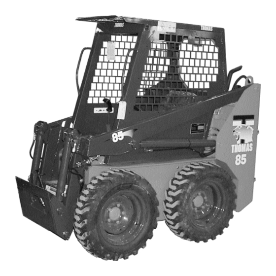
- Page 1 Skid Steer Loader Owner’s Operator’s Manual PUBLICATION NO. 47994 December, 2001...
- Page 2 THOMAS EQUIPMENT LIABILITY WARRANTY THIS WARRANTY IS THE ONLY OBLIGATION OF THOMAS OR A THOMAS DEALER TO THE PURCHASER OR ANYONE ELSE CONCERNING A PRODUCT, ITS SERVICE, ITS USE OR PERFORMANCE OR ITS LOSS OF USE OR FAILURE TO PERFORM. NEITHER THOMAS NOR A THOMAS DEALER...
-
Page 3: Table Of Contents
Special Tools 5. SPECIFICATIONS 5. 1 Loader Specifications 5. 2 Torque Specifications 5. 3 Sound Power Level 5. 4 Decals 6. ATTACHMENTS AND BUCKETS 6. 1 Thomas Approved Buckets 6. 2 Thomas Approved Forks and Grapples 6. 3 Thomas Approved Attachments... - Page 4 FOREWORD This book has been written to give the Owner / Operator necessary operating servicing and preventative maintenance instructions on the loader. Read this manual completely and know the loader before operating or servicing it. Do not do any service procedures that are not in the Operator’s manual. Only service personnel that have had training in the service of this loader can do these service procedures.
-
Page 5: Safety Precautions
10. Do not operate the loader unless all safety equipment, 5. Do not bypass the safety system. Consult your shields, seat belt, seat bar, foot pedal and steering lever Thomas Equipment Dealer if your safety controls are locks, parking brake, operator guard, and boom support malfunctioning. - Page 6 1 SAFETY PRECAUTIONS 12. Keep the operator platform and foot pedal area free from debris. Do not raise the seat bar 13. For lifting and towing instructions, refer to Sections engaging the park brake 3. 7 and 3. 8 of this manual. IMPORTANT while the machine is in motion.
- Page 7 2 CONTROLS 2...CONTROLS 2. 1 Instrument Panel 2. 2 Seat and Seat Belt 2. 3 Seat Bar 2. 4 Parking Brake 2. 5 Throttle Controls 2. 6 Steering Controls 2. 7 Hand Controls 2. 8 Electric Auxiliary Control 2. 9 Foot Pedals 2.
-
Page 8: Instrument Panel
2 CONTROLS 4, 5 Fig. 2. 1 C3066 2. 1 INSTRUMENT PANEL The diesel engine is equipped with glow plugs. 1. Engine Oil Pressure IMPORTANT Do not use ether or any If the light comes on during operation or fails to go out high energy fuels to assist after starting, shut off the engine immediately and starting. -
Page 9: Seat And Seat Belt
For your safety, the loader is equipped with a seat belt. Before starting the loader, adjust and fasten the beat belt around you. (Fig. 2. 2B). The Thomas seat and seat belt also have integrated safety lock switches whereby the operator must be seated in the seat with the belt securely fastened, before the loader can be operated. -
Page 10: Parking Brake
2 CONTROLS n the up position, the seat bar automatically centers the steering controls in neutral. To lower the seat bar, place both hands over the latch, release handles and lift the seat bar slightly (Fig. 2. 3B). Seat Bar Fig. -
Page 11: Throttle Control
2 CONTROLS C3259 Fig. 2. 4B Fig. 2. 5A C-870 Do not park on a slope. If necessary to park on a slope, park across the grade, engage the parking brake, ground the attachment and block the wheels. To avoid personal injury do not start the engine WARNING To prevent possible... -
Page 12: Hand Controls
2 CONTROLS BUCKET CONTROL The right hand lever controls the bucket tilt cylinders. (Fig. 2. 7A) Moving the control lever to the right will cause the bucket cylinders to extend, dumping the bucket. Moving the control lever to the left will cause the bucket cylinders to retract, rolling the bucket back. - Page 13 2 CONTROLS When the auxiliary hydraulic system is not in use return the pedal to the neutral position, otherwise starting the loader may Control Lever Switch (L.H.) be difficult or impossible and damage to the starter motor may occur. Neutral Raise Lift Reverse...
-
Page 14: Foot Pedals
2 CONTROLS C-876 Fig. 2 .8B To avoid personal injury, lower the boom arms, shut off the engine, raise the seat bar and cycle the hydraulics to ensure they are locked. Then, unlatch WARNING the seat belt and exit the loader. -
Page 15: Quick - Tach
2 CONTROLS 2.10 QUICK - TACH The quick - tach, which is standard equipment, allows After hook up to the changing from one attachment to another quickly without attachment check to be IMPORTANT having to remove bolt or pins. sure the pins and locking levers are fully engaged. -
Page 16: Boom Support
2 CONTROLS 2. 11 BOOM SUPPORT 11A), located directly in front of the operator at the top of the operator compartment, outward, extending the boom For safety while performing regular service or support pins (See Fig. 2. 11B). Slowly lower the boom maintenance work, the loader is equipped with boom arms down onto the pins. -
Page 17: Electrical Panel
2 CONTROLS 2. 12 ELECTRICAL PANEL 5. Stop Timer (Y/B) 6. Alternator (B/W) 7. Electrical Auxiliary The loader is equipped with a 12 volt, negative ground electrical system. The fuse and relay panel is located in the 8. Spare engine compartment just in front of the battery box. The 9. - Page 18 3 OPERATION 3...OPERATION 3. 1 Starting Instructions 3.1 A Pre-Starting Inspection 3.1 B Starting Procedure 3.1 C Shut-Off Procedure 3.1 D Shut-Off Procedure Manual 3. 2 Operating Procedure 3. 3 Filling From a Pile 3. 4 Digging With a Bucket 3.
-
Page 19: Starting Instructions
3 OPERATION 3. 1 STARTING INSTRUCTIONS Turn the ignition key counterclockwise to activate the glow plugs. Hold approximately 15 seconds. Both the 3. 1A Pre - Starting Inspection: alternator and engine oil pressure warning lights should be on. Before starting the loader complete the following inspection: Turn the key clockwise to start position to engage the starter. -
Page 20: Filling From A Pile
3 OPERATION 3. 1D Manual Shutoff Procedure Tilt the bucket as you raise the boom arms or drive up a slope. This will prevent material from falling off the Should the engine fail to stop after following the back of the bucket. procedure described in Section 3.1 - C, ensure that the lift arms are lowered and grounded and the foot pedals Do not drive across a slope. -
Page 21: Digging With A Bucket
3 OPERATION To dump the bucket (Fig. 3. 3C) push down on the heel of the boom pedal to raise the bucket. Push down on the toe of the bucket pedal small amounts as the boom arms are raising to stop material from falling off the back of the bucket. -
Page 22: Leveling And Backfilling
3 OPERATION forward. For hand control units, spread dirt on uneven ground by moving the L.H. control lever away from you (Fig. 3. 5A). To raise the boom and move the right hand control lever away from you to tilt the bucket down as you drive forward. C - 716 Fig. -
Page 23: Auxiliary Hydraulics
3 OPERATION 3. 6 AUXILIARY HYDRAULICS To operate an attachment such as a grapple fork (Fig. 3. 6A) using the auxiliary hydraulic circuit, push on the heel of the centre or auxiliary pedal to open the grapple. (See Section 2. 8 for electric solenoid controlled auxiliary). Return the auxiliary control to neutral when not in use otherwise... - Page 24 3 OPERATION To close the grapple (Fig. 3.6B), push down on the toe of auxiliary pedal until the pedal locks in detent position. the auxiliary pedal. The boom and the bucket pedals can be When the auxiliary circuit is not in use return the auxiliary used to raise and tilt the grapple as with a bucket .To pedal to neutral position, otherwise starting the loader may operate an attachment which requires a constant flow of oil...
- Page 25 3 OPERATION Lower the restraint bar to activate the brake system. To prevent personal injury Towing with the restraint bar up could result in DO NOT charge a frozen damage to the braking system. If towing from the battery because it can front, remove the blocks supporting the attachment explode and cause WARNING...
-
Page 26: Lowering Lift Arms
3 OPERATION Connect the end of the second cable to the negative (–) 3. 11B Lift Arm Height Is Not Sufficient To terminal of the booster battery. Connect the other end of the Engage Boom Support Pins same cable to the engine. Keep cables away from moving DO NOT EXIT FROM FRONT OF LOADER parts. - Page 27 4 MAINTENANCE 4 MAINTENANCE 4. 1 Preventative Maintenance Service 4. 8 Air Cleaner Maintenance 4. 8A Daily Maintenance Schedule 4. 8B Servicing Cleaner 4. 2 Service Access Element 4. 2A Boom Support 4. 2B Seat Removal 4. 9 Electrical System 4.
- Page 28 4 MAINTENANCE 4. 1 PREVENTATIVE MAINTENANCE SERVICE SCHEDULE ITEM SERVICE REQUIRED ngine Oil Check0 level and add if necessary. Use 10W30 API Classification SE/CD oil. Radiator Check level and add if necessary. Fill with 50% mixture of ethylene glycol and water. Check cooling fins for dirt. If necessary blow out with compressed air.
- Page 29 • Tighten all connections before starting engine or pressurizing lines. If any fluid is injected into the skin obtain medical attention immediately of gangrene may result. To avoid personal injury service repairs must be WARNING performed by an authorized Thomas dealer.
-
Page 30: Service Access
4 MAINTENANCE 4. 2 SERVICE ACCESS 4. 2A Boom Support: For safety while performing regular service or maintenance work, the loader is equipped with boom support pins. The boom support pins, when extended, prevent the boom arms from dropping if hydraulic pressure is relieved or the foot control pedals accidentally cycled. -
Page 31: Daily Service Checks
4 MAINTENANCE C-951 Fig. 4. 2C Keep the rear door closed except for C-952 Fig.. 4. 2D IMPORTANT servicing. Make sure the door is closed and latched before operating the loader. 4. 2C Engine Compartment The engine compartment is completely enclosed for component protection and lockable to discourage vandalism. - Page 32 4 MAINTENANCE 4. 3C Air Cleaner Service 4. 3E Safety Equipment Inspect the air cleaner service indicator (Fig. 4. 3C). If the Check all safety equipment for proper operation and indicator element shows red, the filter element must be condition - seat belt, boom support, seat bar, foot pedal replaced.
-
Page 33: Hour Service Check
4 MAINTENANCE 4. 4 50 HOUR SERVICE CHECK Keep the rear door The following service check is to be performed by your closed except for dealer after the first 50 hours of operation. servicing. Make sure the IMPORTANT door is closed and Engine latched before operating the loader. - Page 34 API classification SE/CD oil. 5. 2 Battery Terminals: 3. 2 Torque Motor Mounting Bolts: Mounting nuts 85 - 90 ft. lbs (115 - 122 Nm) Check battery terminals for corrosion. If necessary, clean. Jam nuts 40 - 60 ft. lbs. (54 - 81 Nm) 5.
-
Page 35: Final Drive Maintenance
- quarters full in the sight gauge. adjustment consult your Thomas Equipment Dealer for service. Use a good quality 10W30 oil which meets the API classification SE/CD. -
Page 36: Engine Maintenance
4 MAINTENANCE C-954 Fig. 4. 7B C-642P 4. 7 ENGINE MAINTENANCE OIL RESERVOIR DRAIN 4. 7A Oil Level Check Fig. 4. 6C To check the oil level, stop the engine with the loader on 4. 6B Filter Replacement level ground, set parking brake and open the rear door and remove the dipstick (Fig. - Page 37 4 MAINTENANCE To fill the cooling system; close the drain valve. Fill the C-949 Fig. 4. 7F radiator with a 50-50 mixture of ethylene glycol and water. Fill to within .375 inches (10 mm) from the bottom of the filler tube. Refit the radiator cap. 4.
- Page 38 4 MAINTENANCE 4. 7G Bleeding the Fuel System - Diesel: 4. 8 AIR CLEANER MAINTENANCE Be sure that the fuel tank is full and the fuel shut-off cock 4. 8A Daily Maintenance is open. Remove air as follows: Inspect the air cleaner service indicator (Fig. 4. 8) daily. If (1) Open the vent screw on top of the fuel filter until air - the indicator element shows red, the filter element must be free fuel runs from the vent plug.
- Page 39 4 MAINTENANCE 4. 9A ELECTRICAL SCHEMATIC (Engine Side) Engine Wire Harness C3256...
- Page 40 4 MAINTENANCE 4. 9A ELECTRICAL SCHEMATIC (ROPS Side) ROPS Wire Harness C3257...
-
Page 41: Tire Maintenance
4 MAINTENANCE 4. 9B Battery Access • Do not inflate a tire above the manufacturer’s maximum pressure shown on the tire or the maximum The battery is located in the engine compartment behind pressure shown in the table. the electrical panel. Simply remove the two (2) retaining bolts and pull the battery out for service (Fig. -
Page 42: Trouble Shooting
Defective solenoid or stop when the key contact from relay to binding solenoid lock. Contact Thomas Equipment for all major fixes under the is turned OFF solenoid on valve Loosen screws and remedy column except for regular service (i.e. Replenish readjust fluids, tightening etc.). - Page 43 4 MAINTENANCE 4. 11A Electrical (Cont’d) Problem Cause Remedy Problem Cause Remedy No power on both Universal joint Inspect and repair Engine will not Defective fuel Check and correct sides (also loss of failure between damaged parts. Check stop when the key solenoid switch hydraulic power) engine and pump...
- Page 44 4 MAINTENANCE 4. 11C Hydraulic System Problem Cause Remedy Problem Cause Remedy Boom raises slowly Loss of hydraulic Pressure relief valve Check pressure flow Reservoir low on Replenish with 10W30 at full engine RPM power (no flow in control valve and repair or replace oil.
- Page 45 4 MAINTENANCE 4. 11E Control Levers 4. 11F Park Brake Problem Cause Remedy Problem Cause Remedy Control levers will Linkage out of Adjust, check for wear Brake will not hold Slack in cables, Adjust tightening nuts not centre adjustment at rod ends, loose machine cables out of on cables...
- Page 46 4 MAINTENANCE 4. 11G Engine SYMPTOM SOLUTION PROBABLE CAUSE Engine does not start Replenish fuel No fuel Vent air Air in the fuel Change fuel and repair or replace Water in the fuel fuel system Clean Fuel pipe clogged Clean or change Fuel filter clogged Use the specified fuel or engine oil Excessively high viscosity of fuel or engine oil at low...
- Page 47 4 MAINTENANCE 4. 11G Engine SYMPTOM SOLUTION PROBABLE CAUSE Excessive lubricant oil consumption Piston rings gap facing the same direction Shift gap direction Replace Oil ring worn or stuck Replace Piston ring groove worn Replace Valve stem and guide worn Replace Crankshaft bearing and crank pin bearing worn Fuel mixed into lubricant oil...
- Page 48 4 MAINTENANCE 4. 12 HYDRAULIC/HYDROSTATIC CIRCUIT C3266...
-
Page 49: Special Tools
4 MAINTENANCE 4. 13 SPECIAL TOOLS ILLUSTRATION DESCRIPTION MODEL 955280 T103 AXLE INSTALLATION TOOL-To install axle T133 in final drive housing. T133’S’ Quantity-1 960849 SEAL INSTALLATION TOOL-To install axle T103 seal in final drive housing. T133 955281 T133’S’ Quantity-3 required T103 AXLE EXTRACTOR TOOLS- To remove axle 955283... - Page 50 4 MAINTENANCE 4. 13 SPECIAL TOOLS Order # Illustration Description Models 916-30042-01 KUBOTA DRY LINER PULLER - Used for removing and installing the dry liner of the engine. 25197 Consists of: 304742 (64mm); 304743 (68mm); 30744 (75mm) 304745 (76mm); 304746 (82mm); 304747 (105mm);...
- Page 51 5 SPECIFICATIONS 5...SPECIFICATIONS 5. 1 Loader Specifications 5. 2 Torque Specifications 5. 3 Sound Power Level Specifications 5. 4 Decals...
-
Page 52: Specifications
5 SPECIFICATIONS 5. 1 LOADER SPECIFICATIONS Dimensions: Operational: *Rated operating capacity ..900 lbs. (408 kg) A. Overall operating height ..121.5” (3086 mm) Travel speed ....0 - 5.0 mph (0 - 8 km/hr) B. - Page 53 Hydraulic System: Wheel bolts (20) ....85 lbs. ft. (115 Nm) Torque motor drive spkt. nut (2) ..275 lbs. ft.
- Page 57 6 ATTACHMENTS AND BUCKETS 6 ATTACHMENTS AND BUCKETS 6. 1 Thomas Approved Buckets 6. 2 Thomas Approved Forks and Grapples 6. 3 Thomas Approved Attachments...
-
Page 58: Thomas Approved Buckets
Tooth Kit For 36” Bucket (Field) 13lb 1002 Tooth Kit For 42” Bucket (Factory) 15lb Tooth Kit For 42” Bucket (Field) 15lb 6. 2 THOMAS APPROVED FORKS AND GRAPPLES FARM GRAPPLES AND FORKS Cat. # Description Approx. Weight 36” Utility Fork 210lb 42” Utility Fork 240lb 36”... - Page 59 6 ATTACHMENTS AND BUCKETS 6. 3 THOMAS APPROVED ATTACHMENTS HYDRAULIC BREAKER (Requires Side Plates, Mount & Tool) Cat. # Description Approx. Weight 1536 HH150 - 150 Ft.Lbs. Class, Hydraulic Breaker 200lb BREAKER SIDE PLATES & MOUNT Cat. # Description Approx. Weight...
Need help?
Do you have a question about the 85 and is the answer not in the manual?
Questions and answers