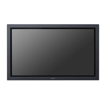
Sony FWD-42PV1 Service Manual

Sony FWD-42PV1 Service Manual

Flat wide display
Hide thumbs Also See for FWD-42PV1:

Advertisement

FLAT WIDE DISPLAY
FWD-42PV1
FWD-42PV1P
FWD-42PV1A
REMOTE COMMANDER
RM-980
SPEAKER SYSTEM
SS-SP42FW
SERVICE MANUAL
1st Edition

Advertisement

Table of Contents
loading
Need help?

Need help?

Do you have a question about the FWD-42PV1 and is the answer not in the manual?

Questions and answers

Subscribe to Our Youtube Channel

Summary of Contents for Sony FWD-42PV1

  • Page 1 FLAT WIDE DISPLAY FWD-42PV1 FWD-42PV1P FWD-42PV1A REMOTE COMMANDER RM-980 SPEAKER SYSTEM SS-SP42FW SERVICE MANUAL 1st Edition...
  • Page 2 Ce manual est destiné uniquement aux personnes compétentes en charge de l’entretien. Afin de réduire les risques de décharge électrique, d’incendie ou de blessure n’effectuer que les réparations indiquées dans le mode d’emploi à moins d’être qualifié pour en effectuer d’autres. Pour toute réparation faire appel à une personne compétente uniquement. FWD-42PV1/42PV1P/42PV1A...
  • Page 3 Gerät abschaltet und signalisiert “Batterie leer” oder nach längerer Gebrauchsdauer der Batterien “nicht mehr einwandfrei funktioniert”. Um sicherzugehen, kleben Sie die Batteriepole z.B. mit einem Klebestreifen ab oder geben Sie die Batterien einzeln in einen Plastikbeutel. 1 (P) FWD-42PV1/42PV1P/42PV1A...
  • Page 5: Table Of Contents

    Va Voltage Adjustment ......... 2-4 2-4. Vsc/_Vy Voltage Adjustment ........2-4 2-4-1. Required Equipment ..........2-4 2-4-2. Vsc Voltage Adjustment ........2-4 _Vy Voltage Adjustment ........2-4 2-4-3. 2-5. Firmware Version Upgrade ..........2-5 2-6. DEVICEINFO Section ........... 2-5 FWD-42PV1/42PV1P/42PV1A...
  • Page 7: Service Overview

    I board TEMP board TEMP board BKM-FW10 L board G board Z SUS board Y SUS board H2 board TEMP board T-L board XR board A board CTRL board YDT board XL board T-R board YDB board H1 board FWD-42PV1/42PV1P/42PV1A...
  • Page 8: Disassembly

    1-3-1. Rear Cabinet Assembly 7 Hold the two handles and remove the rear cabinet assembly. 6 Nineteen screws 3 Four screws 1 Panel securing screws 4 Four knobs 2 BKM-FW10 5 Fourteen screws 8 Rear cabinet assembly Conductive cushion Upper side FWD-42PV1/42PV1P/42PV1A...
  • Page 9: Bezel Assembly/H1 Board/H2 Board

    !- Two screws 2 Ten screws != Control button bracket 0 Front frame assembly !\ Control button !] H2 board 4 Filter glass ![ Three screws Conductive cushion Upper side 3 Harness 6 Bezel assembly 7 Two screws 8 H1 board FWD-42PV1/42PV1P/42PV1A...
  • Page 10: A Board/L Board/I Board

    3 Two screws 4 I board 9 Two screws CN201 CN28 8 Four screws !/ Cover 1 Four screws !- A board CN302 7 Interface cover 5 Six connector screws CN301 CN303 6 Screw 2 L board Upper side Conductive cushion FWD-42PV1/42PV1P/42PV1A...
  • Page 11: G Board/Temp Board

    . Remove the rear cabinet assembly. (Refer to Section 1-3-1.) 7 Option shield plate 1 Three screws 5 Screws CN1304 8 Two screws 2 AC outlet cover CN1302 4 T-R board 9 T-L board 6 Screw 3 Two screws Conductive cushion Upper side FWD-42PV1/42PV1P/42PV1A...
  • Page 12: A Block Assembly/Dc Fan

    !\ Fan bracket (lower) Upper side 9 Two screws !/ DC fan Conductive cushion 7 Two screws 8 Fan bracket DC fan installation direction Make sure that the label is oriented in the upward direction of the main unit. FWD-42PV1/42PV1P/42PV1A...
  • Page 13: Ydt Board/Ydb Board

    . Remove the bezel assembly. (Refer to Section 1-3-2.) . Remove the YDT board and YDB board. (Refer to Section 1-3-7.) 1 Six screws 2 Y SUS board 4 Three board brackets Upper side 3 Six screws Conductive cushion FWD-42PV1/42PV1P/42PV1A...
  • Page 14: Ctrl Board

    4 CTRL board Upper side Conductive cushion 1-3-10. Z SUS Board . Remove the rear cabinet assembly. (Refer to Section 1-3-1.) . Remove the bezel assembly. (Refer to Section 1-3-2.) 1 Five screws 2 Z SUS board Upper side Conductive cushion FWD-42PV1/42PV1P/42PV1A...
  • Page 15: Xl Board/Xr Board

    . Remove the A block assembly. (Refer to Section 1-3-6.) 1 Four screws 2 Two frame modules 7 Four screws 8 XR board 9 Harness 3 Six screws 5 Four screws 4 Flexible retainer 6 XL board Upper side Conductive cushion FWD-42PV1/42PV1P/42PV1A...
  • Page 16: Plasma Display Panel

    1-3-12. Plasma Display Panel . Remove each part. (Refer to Sections 1-3-1 to 1-3-11.) 5 Four screws 1 Four screws 3 Two screws 6 Speaker bracket supports 4 AC socket support 2 Speaker bracket supports 1-10 FWD-42PV1/42PV1P/42PV1A...
  • Page 17: Service Position

    . When assembling the service position, be sure to repair after removing the rear cabinet. A board Unit 1 Knobs 2 Four screws Insert the four knobs into the holes of stands. 1 Knobs Unit Stands Unit Stands 1-11 FWD-42PV1/42PV1P/42PV1A...
  • Page 18: Packing Of The Plasma Display Panel

    5 Protection plate for outer box Rear 3 Inner box (front) 2 Protection plate for inner box 4 Inner box (rear) 5 Protection plate for outer box 2 Protection plate for inner box 1 PDP module 6 Palette 1-12 FWD-42PV1/42PV1P/42PV1A...
  • Page 19: Warning On Power Connection

    . The ordinary soldering iron can be used but the iron tip has to be applied to the solder joint for a slightly longer time. The printed pattern (copper foil) may peel away if the heated tip is applied for too long, so be careful. 1-13 FWD-42PV1/42PV1P/42PV1A...
  • Page 21: Service Mode And Adjustment

    . AGING ON/OFF . FAN ON/OFF . CONTRAST-R . BRIGHT-B . INIT GOODS . CONTRAST-G . CLOCK . CONTRAST-B . PHASE FOR SONY . BRIGHT-R . AUTO . S-INIT GOOD . SELECT RS232 . BRIGHT-G . FAN FOR TEST AD CALIBRATION TEMPERATURE .
  • Page 22: Description Of Main Items

    2-1-3. Description of Main Items 5. FOR SONY S-INIT GOOD: Initializes whole data except Operation 1. AD CALIBRATION Time for user to be able to use the set. PC.CUTOFF: Sets Cut Off of PC mode. FAN FOR TEST: Sets fan on/off.
  • Page 23: White Balance Adjustment

    1. Start the on service mode. . 1080I (Y/Pb/Pr) (Refer to Section 2-1-1.) . 480P (Y/Pb/Pr) 2. After selecting FOR SONY menu, run S-INIT GOODS. . NTSC composite When the setting is completed, the unit becomes ON . PAL composite state automatically after power ON/OFF.
  • Page 24: Va/Vs Voltage Adjustment

    _Vy check volume point Measurement point (Connector that is connected from the G board to the Z SUS board) _Vy specification value Vsc specification value The above is a label sample. Check the actual model for the actual specification value. FWD-42PV1/42PV1P/42PV1A...
  • Page 25: Firmware Version Upgrade

    1. Connect this unit with PC using the RS-232C cable. 2. Set the port. 2. Disconnect the AC power cord of this unit. (1) Select the model. (FWD-42PV1) 3. Copy the ISP program to the arbitrary folder. (2) Select the port. (COM1, COM2, COM3 or COM4) 4.
  • Page 27: Troubleshooting

    → Replace the G board. Cause 2: If it is not, replace the A board. 5. Blinking red LED many times. 2. Abnormal sound Refer to Section 3-1. Cause 1: Replace the L board. FWD-42PV1/42PV1P/42PV1A...
  • Page 28: Plasma Display Panel

    2. Vertical bar failure . Check all connectors. . Check peripheral circuit and connecting of the XR and XL borads. 3. Horizontal bar failure . Check all connectors. . Check peripheral circuit and connecting of the YDT and YDB borads. FWD-42PV1/42PV1P/42PV1A...
  • Page 29: Image Trouble

    Replace the Y SUS board. After replacing the G board, perform the following adjustments. . Vsc Adjustment (Refer to Section 2-4.) . _Vy Adjustment (Refer to Section 2-4.) Is the Z SUS board abnormal? Replace the Z SUS board. FWD-42PV1/42PV1P/42PV1A...
  • Page 30: Power (G Board) Trouble

    Is the G board abnormal? Replace the G board. After replacing the G board, perform the following adjustments. . Va Voltage Adjustment (Refer to Section 2-3.) . Vs Voltage Adjustment (Refer to Section 2-3.) Is the CTRL board abnormal? Replace the CTRL board. FWD-42PV1/42PV1P/42PV1A...
  • Page 31: Remote Control Trouble

    Replace the A board. After replacing the parts, perform the following adjustments. . AD calibration adjustment (Refer to Section 2.) . White balance adjustment (Refer to Section 2.) . EDID data input . S-init Goods (Refer to Section 2.) FWD-42PV1/42PV1P/42PV1A...
  • Page 32: Other Trouble

    After replacing the parts, perform the following adjustments. . AD calibration adjustment (Refer to Section 2.) . White balance adjustment (Refer to Section 2.) . EDID data input . S-init Goods (Refer to Section 2.) Connect the DC fan correctly. FWD-42PV1/42PV1P/42PV1A...
  • Page 33: Plasma Display Panel

    Replace the Y SUS or Z SUS board. After replacing the G board, perform Y SUS and Z SUS boards the following adjustments. abnormal? . Vsc Adjustment (Refer to Section 2-4.) . _Vy Adjustment (Refer to Section 2-4.) Replace the CTRL board. FWD-42PV1/42PV1P/42PV1A...
  • Page 34: Vertical Image Is Abnormal

    IS the CTRL board abnormal? Replace the CTRL board. Replace the plasma display After replacing the parts, perform the following panel. adjustments. . AD calibration adjustment (Refer to Section 2.) . White balance adjustment (Refer to Section 2.) FWD-42PV1/42PV1P/42PV1A...
  • Page 35: Horizontal Image Is Abnormal

    After replacing the G board, perform Replace the YDT, YDB, Y SUS, the following adjustments. or CTRL board. . Vsc Adjustment (Refer to Section 2-4.) . _Vy Adjustment (Refer to Section 2-4.) FWD-42PV1/42PV1P/42PV1A...
  • Page 37: Spare Parts

    Therefore, specified parts should be used in the case of replacement. 2. Standardization of Parts Some repair parts supplied by Sony differ from those used for the unit. These are because of parts common- ality and improvement. Parts list has the present standardized repair parts.
  • Page 38: Exploded Views

    Screw Kit 4-2. Exploded Views 12 b 10 c FWD-42PV1/42PV1P/42PV1A...
  • Page 39 Screw Kit 18 19 Note : The screws can be ordered in units of screw kit. (Sony part No. 20 to 22) Part No. SP Description Part No. SP Description Part No. SP Description X-2022-847-1 s SCREW KIT, WALL MOUNT...
  • Page 40 SP Description X-2024-229-1 s ASSY,FRONT FRAME 1-789-198-11 s MOUNTED CIRCUIT BOARD, H2 X-2055-050-1 s BEZEL ASSY (SILVER) 1-789-199-11 s MOUNTED CIRCUIT BOARD, H1 (for FWD-42PV1/42PV1A) X-2055-051-1 s BEZEL ASSY (BLACK) 2-591-335-01 s BUTTON, CONTROL (for FWD-42PV1) 2-591-336-01 s BRACKET, CONTROL BUTTON...
  • Page 41 1-789-195-11 s MOUNTED CIRCUIT BOARD, T-R 1-789-196-11 s MOUNTED CIRCUIT BOARD, T-L 1-789-197-11 s MOUNTED CIRCUIT BOARD, I 1-789-200-11 s MOUNTED CIRCUIT BOARD, L 1-789-201-11 s MOUNTED CIRCUIT BOARD, A 2-591-337-01 o COVER, INTERFACE 2-591-338-01 s COVER, AC OUTLET 2-990-241-02 s HOLDER (A), PLUG FWD-42PV1/42PV1P/42PV1A...
  • Page 42 1-789-205-11 s MOUNTED CIRCUIT BOARD, Y SUS 1-789-206-11 s MOUNTED CIRCUIT BOARD, YDB 1-789-207-11 s MOUNTED CIRCUIT BOARD, YDT 1-789-208-11 s MOUNTED CIRCUIT BOARD, XL 1-789-209-11 s MOUNTED CIRCUIT BOARD, CTRL 1-789-210-11 s MOUNTED CIRCUIT BOARD, XR 1-805-839-11 s DISPLAY PANEL, PLASMA FWD-42PV1/42PV1P/42PV1A...
  • Page 43 2-990-242-01 s HOLDER (B),PLUG 3-613-640-01 o HOLDER (C), PLUG 3-674-673-01 o STOPPER (A) 4-101-214-01 s HOLDER, CABLE 4-101-219-01 o TRAY, BOTTOM 4-101-222-01 o CARTON, INSIDE 4-101-223-01 o BAG, PROTECTION 4-101-224-01 o ACCESSORY BOX ------------ CORD, POWER (See Sec.1-6. Warning on Power Connection) FWD-42PV1/42PV1P/42PV1A...
  • Page 44: Overall

    A-1083-765-A s SPEAKER ASSY (42R) (RP) WHITE (FOR SS-SP42FW/W (PEARL WHITE)) A-1081-103-A s SPEAKER ASSY (42L) (RP) SILVER (FOR SS-SP42FW/S (SILVER)) A-1083-766-A s SPEAKER ASSY (42L) (RP) WHITE (FOR SS-SP42FW/W (PEARL WHITE)) 7-682-963-09 s SCREW +PSW 4X12(EP-FE/ZNBK/CM2) 7-685-661-14 s SCREW +BVTP4X12(EP-FE/CU,NI,CR) FWD-42PV1/42PV1P/42PV1A...
  • Page 45 1-910-012-52 o CONNECTOR ASSY 8P Z SUS 1-910-012-55 o CONNECTOR ASSY 8P MAIN 1-910-012-56 o CONNECTOR ASSY 12P AU 1-910-012-57 o CONNECTOR ASSY 8P RMT 1-910-012-59 o CONNECTOR ASSY 4P SPK L . The numbers encircled by round corresponds to those of the left illustration. FWD-42PV1/42PV1P/42PV1A...
  • Page 47 Overall Section 5 Block Diagram Overall FWD-42PV1/42PV1P/42PV1A...
  • Page 50 FWD-42PV1 (SY) FWD-42PV1P (SY) Printed in Japan Sony Corporation FWD-42PV1A (SY) E 2005. 7 22 9-878-346-01 ©2005...

This manual is also suitable for:

Fwd-42pv1pFwd-42pv1a

Table of Contents