Table of Contents
Advertisement
Quick Links
Advertisement
Table of Contents

Related Manuals for Audison Thesis HV venti


Summary of Contents for Audison Thesis HV venti
-
Page 2: Table Of Contents
CONTENTS INTRODUCTION GENERAL RECOMMENDATIONS ....page Safety precautions Functioning precautions Maintenance and reliability precautions INTRODUCTION DESCRIPTION ....page 1 • Project purpose 2 • Project philosophy 3 • Electronics 4 • Chassis and thermal project 5 • Installation method and maintenance TECHNICAL DATA TECHNICAL AND ELECTRICAL FEATURES .... -
Page 3: Introduction General Recommendations
INTRODUCTION GENERAL RECOMMENDATIONS Safety precautions • The vehicle electric system must have 12VDC voltage with negative to ground. Make sure your car has it in order to avoid any damages to your amplifier and to the car itself. • Suitably fix the amplifier paying utmost attention if you install it into the driver’s compartment. Use extra fixing systems if you install it inside the bonnet. -
Page 4: Introduction Description
Therefore a new version of these classics may have changed their look, maybe also some of their features, but not their sound specifi cations. However there was still a way for Audison to try to improve, by merging these two unique characters into one amplifi er. This has been the idea of Audison engineers for a very long time. -
Page 5: Electronics
INTRODUCTION DESCRIPTION The fi nal power stage uses an innovative topology, which aims at increasing Class “A” polarization as much as possible. The whole input circuit is balanced up to the fi nal stage “Front End”, while the amplifi er’s confi guration is “Dual Mono”. In order to avoid electro-magnetic interferences, no high current is passed on the main board, with the exception of power supply terminals;... -
Page 6: Introduction
INTRODUCTION DESCRIPTION JFET differential input stage (available in PRE ON confi guration). Selectable two level input gain structure adjusted (available in PRE ON confi guration). Balanced output buffer for control unit (available in PRE ON confi guration). Thermally stabilized (available in PRE ON confi guration). Control Unit: Allows the amplifi... - Page 7 However, they are synchronized with one another and are designed to supply one single power source, one supplies the positive and the other the negative power. This solution, which has been employed by Audison for a very long time, allows engineers to increase the impulsive current transient response necessary to the amplifi er.
-
Page 8: Chassis And Thermal Project
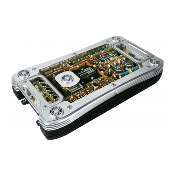
For cosmetic effect, the HV venti is equipped with three styles of lighting: the Thesis logo and glass perimeter red, the Audison logo blue, and the internals of the amplifi er are lit white. If the user removes the glass top plate, there are no electric wires to disconnect or reconnect, as electric contact automatically occurs through spring loaded contacts;... -
Page 9: Installation Method And Maintenance
Once fi lters are dried, they can be put back to their place. Do not use an external heat source to dry the foam fi lters. Now you can remount the grilles. You can fi x them in four different ways according to which Audison logo side you want to be visible. -
Page 10: Technical Data Technical And Electrical Features
TECHNICAL DATA TECHNICAL AND ELECTRICAL FEATURES ELECTRICAL FEATURES POWER SUPPLY Voltage: ..........................11 ÷ 16 VDC Remote IN: ........................7 ÷ 16 VDC - 1mA Idling current when off: ....................0.006 mA Minimum idling current • Low BIAS: ................(Hi Current) 4.2 A ......(Hi Power) 5.6 A •... -
Page 11: Owner's Manual Inputs - Outputs Panel
MONO confi guration, take negative output from + Right terminal block. Remark: ABS (Audison Balanced System) connector. If you want to use balanced lines, you need to employ the special extension with ABS connector which you can fi nd in AUDISON CONNECTION catalogue. -
Page 12: Owner's Manual Power Supply - Switching On Panel
OWNER’S MANUAL POWER SUPPLY - SWITCHING ON PANEL 1 • - POWER (GROUND) Terminal block for the amplifi er power supply negative pole connection. Connect the battery negative cable or the one connected to the vehicle chassis to it. Holes have 9.5 mm (.37 inches) diameter and accept cables up to 2 A.W.G. For better current transfer, power supply cables have to be as big as possible. -
Page 13: Owner's Manual Controls Panel
OWNER’S MANUAL CONTROLS PANEL 1 • OUT MODE It permits to confi gure the amplifi er in STEREO or MONO. If you put Out Mode control on STEREO, PRE IN LEFT and RIGHT inputs signals are separately amplifi ed and they are in SPEAKER LEFT and RIGHT outputs. -
Page 14: Owner's Manual
OWNER’S MANUAL CONTROL FUNCTIONS AND PROTECTION ASC – Amplifi er Status Controller Unit ASC handles all the amplifi er functions, except sound. It has a microprocessor and through its Status Display, it permits to visualise working functions and possible anomalies both of the amplifi... -
Page 15: Glass Panel Removal
Caution!: Panel is made of very sturdy, tempered glass but we suggest you avoid any bumps against hard objects. Handle with care. In case it breaks, it will generate countless little pieces which are not harmful for your hands. Contact Audison service centres in order to replace it. -
Page 16: Main Fuse Replacement
OWNER’S MANUAL MAIN FUSE REPLACEMENT a. Remove the glass panel: see 5 OWNER’S MANUAL GLASS PANEL REMOVAL b. Remove the side handle above power supply terminal blocks: 6 OWNER’S MANUAL SIDE HANDLES REMOVAL c. Lift the plexiglass panel which protects power supply terminal blocks d. -
Page 17: Dual Power Configuration
DUAL POWER CONFIGURATION OWNER’S MANUAL a. Remove the glass panel: see 5 OWNER’S MANUAL GLASS PANEL REMOVAL b. Remove the side handle above power supply terminal blocks: 6 OWNER’S MANUAL SIDE HANDLES REMOVAL c. Lift the plexiglass panel which protects power supply terminal blocks d. -
Page 18: Mount Power Supply Terminal Blocks Protecting Panel
OWNER’S MANUAL DUAL POWER CONFIGURATION e. Mount power supply terminal blocks protecting panel f. Mount the side handle back: see 6 OWNER’S MANUAL SIDE HANDLES REMOVAL g. Reassemble the glass panel: see 5 OWNER’S MANUAL GLASS PANEL REMOVAL DUAL BIAS CONFIGURATION OWNER’S MANUAL a. -
Page 19: Crossover Installation
CROSSOVER INSTALLATION OWNER’S MANUAL a. Remove the glass panel: see 5 OWNER’S MANUAL GLASS PANEL REMOVAL b. Remove the bypass module by unfastening the two screws which secure it inside the product. c. Select the fi lter and the frequency you like by moving connectors upwards or downwards and turning the module. -
Page 20: Accessories Supplied With Hv Venti
OWNER’S MANUAL INSTALLATION a. Accessories supplied with HV venti Audison sticker INOX “CARD” Certifi cate of property with HV venti serial number Crossover module Insulated pliers to remove mini-fuses 10A blade mini-fuses 100A strip fuse 2mm and 4mm spanners Connections covering grilles and fi... -
Page 21: How To Take The Amplifi Er Out Of Its Inner Carton
OWNER’S MANUAL INSTALLATION b. How to take the amplifi er out of its inner carton Take the amplifi er out of its inner carton using the side handles. Caution!: the adhesive drilling template is under the amplifi er inner carton. c. -
Page 22: Owner's Manual Installation
INSTALLATION OWNER’S MANUAL f. NON-PROJECTING or SEMI-PROJECTING installation HOW TO USE THE ADHESIVE DRILLING TEMPLATE The drilling template is useful for NON-PROJECTING or SEMI-PROJECTING installation. It is not necessary if installations totally project from the surface. It has two functions: 1) It permits to drill the fi... -
Page 23: Remove The Amplifi Er Fi Xing Plate
OWNER’S MANUAL INSTALLATION g. Remove the amplifi er fi xing plate h. Secure the fi xing plate through 8 screws at least Screws diameter must be 4mm (.15 inches) max. - 22 -... -
Page 24: Secure The Amplifi Er To The Fi Xing Plate
OWNER’S MANUAL INSTALLATION i. Secure the amplifi er to the fi xing plate j. Connect signal cables: see 1 OWNER’S MANUAL INPUTS - OUTPUTS PANEL k. Connect power supply cables: see 2 OWNER’S MANUAL POWER SUPPLY PANEL l. Amplifi er calibration: see 3 OWNER’S MANUAL CONTROLS PANEL m. -
Page 25: Owner's Manual Maintenance
OWNER’S MANUAL MAINTENANCE a. Fans protecting fi lters cleaning This operation has to occur every six months approx. 1 • Remove the magnetic grilles which protect fans. 2 • Remove the three foam fi lters and clean them with water and soap.
Need help?
Do you have a question about the Thesis HV venti and is the answer not in the manual?
Questions and answers