Table of Contents
Advertisement
Quick Links
ELGAR ELECTRONICS CORPORATION
9250 Brown Deer Road
San Diego, CA 92121-2294
1-800-733-5427
Tel: (858) 450-0085
Fax: (858) 458-0267
Email: sales@elgar.com
www.elgar.com
This document contains information proprietary to Elgar Electronics Corporation. The information contained herein is not
to be duplicated or transferred in any manner without prior written permission from Elgar Electronics Corporation.
June 27, 2003
CW-P SERIES
PROGRAMMABLE
AC POWER SOURCE
Operation Manual
This manual covers models:
CW 801P
CW 1251P
CW 2501P
CW 801P–H
CW 1251P–H
CW 2501P–H
CW 801P–V
CW 1251P–V
CW 2501P–V
©2003 by Elgar Electronics Corporation
Document No. M161691-01 Rev H
Advertisement
Table of Contents

Related Manuals for Elgar CW 801P


Summary of Contents for Elgar CW 801P
- Page 1 ©2003 by Elgar Electronics Corporation This document contains information proprietary to Elgar Electronics Corporation. The information contained herein is not to be duplicated or transferred in any manner without prior written permission from Elgar Electronics Corporation. June 27, 2003 Document No. M161691-01 Rev H...
- Page 5 All the safety instructions and advice notes are to be followed. Neither Elgar Electronics Corporation, San Diego, California, USA, nor any of the subsidiary sales organizations can accept any responsibility for personnel, material or inconsequential injury, loss or...
- Page 6 SAFETY SYMBOLS CAUTION CAUTION Risk of Electrical Shock Refer to Accompanying Documents Off (Supply) Direct Current (DC) Standby (Supply) Alternating Current (AC) On (Supply) Three–Phase Alternating Current Protective Conductor Terminal Earth (Ground) Terminal Fuse Chassis Ground...
- Page 7 Buyer returns the defective product in the original, or equivalent, shipping container; • if, upon examination of such product by Elgar it is disclosed that, in fact, a defect in materials and/or workmanship does exist, that the defect in the product was not caused by improper conditions, misuse, or negligence;...
- Page 8 This page intentionally left blank.
-
Page 9: Table Of Contents
CONTENTS SECTION 1 INTRODUCTION............1-1 SECTION 2 SPECIFICATIONS............2-1 2.1 Output....................2-1 2.2 Measurement..................2-3 2.3 Input ..................... 2-5 2.4 Protection ..................... 2-6 2.5 Rear Panel Connections............... 2-6 2.6 General....................2-6 2.7 Options and Accessories ..............2-7 SECTION 3 INSTALLATION .............3-1 3.1 Unpacking..................... 3-1 3.2 Wire Gauge Selection................ - Page 10 Contents Elgar CW-P Series 3.8 Remote Control Signal ................3-15 3.8.1 Analog Amplitude Control ............3-15 3.8.2 Lock to External Frequency Source.........3-15 3.8.3 Sync Output Pulse..............3-16 3.9 Master/Slave Configurations ...............3-16 3.9.1 Setup for Single–Phase, Two Units .........3-17 3.9.2 Setup for Three–Phase, Two Units per Phase ......3-20 SECTION 4 OPERATION ..............
- Page 11 MAINTENANCE .............6-1 6.1 Periodic Service..................6-1 6.2 Fuse Replacement ................6-1 LIST OF FIGURES Figure 1–1 ContinuousWave Front Panel (Model CW 801P)......1-1 Figure 3–1 Slide Mounting ................3-5 Figure 3–2 Mounting Dimensions, Front and Rear Views (CW 801P and CW 1251P)............3-6 Figure 3–3...
- Page 12 Contents Elgar CW-P Series LIST OF TABLES Table 3–1 Recommended Wire Gauge Selection Guide ......3-2 Table 3–2 Recommended Cables ............. 3-11 Table 6–1 Replacement Fuses ..............6-1 viii Operation Manual...
-
Page 13: Introduction
SECTION 1 INTRODUCTION Elgar's ContinuousWave™ (CW) Series power sources deliver 800 VA or 1250 VA in a 2U high (3.5 inches), and 2500 VA in a 5.25–inch benchtop or rackmount chassis. Higher power and multiphase can be achieved by paralleling and multiphase interconnection. - Page 14 • 0 to 135V and 0 to 270V ranges; 0 to 155V and 0 to 310V ranges with V–Option • CW 801P and CW 1251P versions have universal output socket on front panel. All units have output power available at rear of unit.
-
Page 15: Specifications
SECTION 2 SPECIFICATIONS Output POWER CW 801P 800 VA CW 1251P 1250 VA CW 2501P 2500 VA Power Factor of Load 0 lag to 0 lead Phase All models single phase output VOLTAGE Ranges 0 to 135 VRMS or 0 to 270 VRMS, user selectable V–Option: 0 to 155 VRMS or 0 to 310 VRMS, user... - Page 16 16.2 ARMS (155 VAC range), 8.1 ARMS (310 VAC range) Accuracy ±0.5% of full scale typical; for linear loads and >0.12 ARMS for CW 801P, >0.19 ARMS for CW 1251P, >0.37 ARMS for CW 2501P H–Option/V–Option: ±0.75% of full scale and ≤500 Hz; ±1.0% of full scale and >500Hz...
-
Page 17: Measurement
0 to 18.6 ARMS Accuracy ±0.5% of range typical; for linear loads and >0.12 ARMS for CW 801P, >0.19 ARMS for CW 1251P, >0.37 ARMS for CW 2501P H–Option/V–Option: ±0.75% of range and ≤500 Hz; ±1.0% of range and >500 Hz Resolution 0.01 ARMS... - Page 18 Specifications Elgar CW-P Series PEAK INRUSH CURRENT* (Available in Remote Mode only) Range CW 801P 0 to 25A CW 1251P 0 to 35A CW 2501P 0 to 70A Accuracy ±2% of range, typical; at >2% of RMS current range Resolution 0.1A...
-
Page 19: Input
POWER FACTOR >73% typical at full load EFFICIENCY H–Option/V–Option at 1,000 Hz: CW 801P, >68% typical; CW 1251P, >70% typical; CW 2501P, >72% typical *Note: In a parallel system, the current/power displayed on the master unit is the sum of all units in the system. -
Page 20: Protection
Protection Overcurrent: Shutdown mode Accuracy: +/- 1% of full scale, for linear loads with current >0.2 ARMS for CW 801P / CW 1251P, >0.4ARMS for CW 2501P Over Voltage: Accuracy: +/-2% of full scale Range: 35-300 VAC; V–Option: 35-344 VAC... -
Page 21: Options And Accessories
40,000 feet Installation Category III, Pollution Degree 2 FOR INDOOR USE ONLY Options and Accessories Rack Slide Kit (Elgar part number K161570-01) Multiphase/Parallel Cable (Elgar part number 890-499-00) Master/Slave Cable (Elgar part number 890-497-40) S: Sync In/Out (Clock/Lock) H: Expanded Frequency Range 45 to 1000 Hz V: Expanded Voltage Range 0-155/0-310 VRMS Note: Product specifications are subject to change without notice. - Page 22 Specifications Elgar CW-P Series This page intentionally left blank. Operation Manual...
-
Page 23: Installation
In addition, the shipping container(s) and filler material should be saved for inspection. Forward a report of damage to the Elgar Service Department. Elgar will provide instructions for repair or replacement of the instrument. -
Page 24: Wire Gauge Selection
Thus, this guide applies equally to the input cable and output cable for this Elgar instrument and application loads. Power cables must be able to safely carry maximum load current without overheating or causing insulation destruction. - Page 25 Elgar CW-P Series Installation The following notes apply to Table 3–1 and to the power cable definition: The above figures are based upon insulated copper conductors at 25ΕC (77ΕF), two current carrying conductors in the cable plus a safety (chassis) ground.
- Page 26 Current Capability 3 to 6 Above 6 The preferred insulation material is application dependent. Elgar's recommend- ation is any flame retardant, heat resistant, moisture resistant thermoplastic insulation rated to a nominal 75°C (167°F). Voltage breakdown must exceed the combined effects of: •...
-
Page 27: Mounting Instructions
The units are 3.5" and 5.25" (89 mm and 133 mm) high, and are designed to be installed in a standard 19" (483 mm) RETMA rack. Pem-nuts have been built into the chassis for mounting optional slides. The CW mounting kit, Elgar part number K161570-01, contains the appropriate slides and mounting brackets. -
Page 28: Figure 3-2 Mounting Dimensions, Front And Rear Views
Installation Elgar CW-P Series Figure 3–2 Mounting Dimensions, Front and Rear Views (CW 801P, CW 1251P) Operation Manual... -
Page 29: Figure 3-3 Mounting Dimensions, Front And Rear Views (Cw 2501P)
Elgar CW-P Series Installation Figure 3–3 Mounting Dimensions, Front and Rear Views (CW 2501P) Operation Manual... -
Page 30: Figure 3-4 Mounting Dimensions, Top And Side Views (Cw 801P And Cw 1251P)
Installation Elgar CW-P Series Figure 3–4 Mounting Dimensions, Top and Side Views (CW 801P and CW 1251P) Operation Manual... -
Page 31: Figure 3-5 Mounting Dimensions, Top And Side Views (Cw 2501P)
Elgar CW-P Series Installation Figure 3–5 Mounting Dimensions, Top and Side Views (CW 2501P) Operation Manual... -
Page 32: Power In Connections
Installation Elgar CW-P Series Power In Connections Connect input power to the INPUT terminal block on the rear panel as specified below. Refer to Figure 3–6. Figure 3–6 Input Power Connections WARNING! For input voltages >120V, do not reverse LINE and NEUT. -
Page 33: Split-Phase Supply Connections 120-0-120V
Elgar CW-P Series Installation 3.5.2 Split-Phase Supply Connections 120–0–120V 1. Remove the protective cover from the terminal block. 2. Route the cables through the strain relief device. Refer to Table 3–2 for cable recommendations. 3. Connect NEUT to 120V. 4. Connect LINE to the other 120V. -
Page 34: Power Out Connections
Installation Elgar CW-P Series Power Out Connections 1. Remove the protective cover from the terminal block. 2. A factory jumper has been added to connect NEUTRAL to GROUND. If the front connector requires LINE and NEUTRAL to be reversed, move this jumper to connect LINE to GROUND. -
Page 35: Sense Connections
Elgar CW-P Series Installation Sense Connections The CW Series unit can be used with or without remote sense leads connected to the load. Where the sense leads (line and neutral sense) are connected determines the point at which the CW output voltage will be precisely regulated. -
Page 36: Figure 3-9 Sense Connections
Installation Elgar CW-P Series To utilize remote sensing at the user's load, follow these steps: 1. Remove the protective cover from the terminal block. 2. Route the cables through the strain relief device located above the terminal block. Twisted shielded leads for power and sense leads are recommended for the lowest noise operation. -
Page 37: Remote Control Signal
Elgar CW-P Series Installation Remote Control Signal Remote control allows you to set output voltage, lock to an external frequency source, or send out a TTL compatible sync signal. The 9-pin Subminiature-D master/slave connector labeled M/S IN on the rear panel allows you to make the necessary connections for remote control. -
Page 38: Sync Output Pulse
Installation Elgar CW-P Series 3.8.3 Sync Output Pulse • Set direction of Clock to ‘OUT’ (see Section 5.3.9). • Sync can be programmed relative to zero to positive crossing of output sinewave. Waveform amplitude typically 5V. Pulse width typically 10 microseconds. Signal shall start with a zero volt to positive voltage edge, ±100 µS. -
Page 39: Setup For Single-Phase, Two Units
Power down all CW units. Connect load wiring as documented below. Connect M/S OUT and M/S IN cables (Elgar PN 890-499-00) between each CW in a daisy chain pattern. 10. Connect master/slave, analog slave cables (Elgar PN 890-497-40) from master to slave, one on each master/slave pair. - Page 40 20. Rotate the right knob until the right display reads “1”. 21. Press the ENTER/SAVE button. 22. Power down both CW power supplies. 23. Connect Elgar cable 890-497-40 between the master “Analog Slave” and the slave “Analog Slave” connectors. 3-18...
- Page 41 Elgar CW-P Series Installation 24. Connect the Elgar cable 890-499-00 between the master “M/S OUT” and the slave “M/S IN” connectors. 25. Connect the load wiring as shown in Figure 3–11 above. 26. Power up both CW units simultaneously. 27. Control the master/slave pair by controlling the CW master via the front panel or its command interface.
-
Page 42: Setup For Three-Phase, Two Units Per Phase
Installation Elgar CW-P Series 3.9.2 Setup for Three–Phase, Two Units per Phase Figure 3–12 Wiring Diagram for Three Phase, Master/Slave Configuration 3-20 Operation Manual... - Page 43 Elgar CW-P Series Installation Setup Six CW Units as 3–Phase Master/Slave Set using Menu System Ensure load wiring is removed from the six CW units. Ensure no master/slave cables are attached to “Analog Slave” connectors on CW’s. Ensure no master/slave cables are connected to the “M/S IN “ and “M/S OUT”...
- Page 44 Installation Elgar CW-P Series 26. Rotate the right knob until the right display reads “A”. 27. Press the ENTER/SAVE button. 28. Set up the B phase. 29. On the B master CW press the “ENTER/SAVE” button. 30. Rotate the left knob until the left display reads “Addr”.
- Page 45 67 through 71. As long as A master is the origin, all other daisy chained units can be in any order. 67. Connect the Elgar cable 890-499-00 between the A master “M/S OUT” and the A slave “M/S IN”.
- Page 46 Installation Elgar CW-P Series This page intentionally left blank. 3-24 Operation Manual...
-
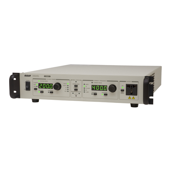
Page 47: Operation
The controls and indicators on the front panel of the CW are detailed below. Refer to Figure 4–1. Figure 4–1 Front Panel Controls (CW 801P) Power Switch Press the top portion of the switch to turn power on, press the bottom portion of the switch to turn the power supply off. - Page 48 Operation Elgar CW-P Series Numeric Display. The large, four-digit display in the VOLTAGE/POWER section is a digital voltmeter that measures and displays the power supply’s voltage/power parameters. If the CW is operating with output power turned off, this meter displays the voltage that the output will assume when it is turned on.
- Page 49 Elgar CW-P Series Operation ESCAPE Button. Press this button to exit the Menu function without saving parameter changes. Note that this button only abandons the change to the currently selected parameter; previous parameter modifications that were completed using the ENTER/SAVE button are unaffected.
-
Page 50: Front Panel Overview
Operation Elgar CW-P Series OUTPUT Section This section is used to open and close the output relay. Output terminals are available in the universal AC connector located in the OUTPUT section, as well as on the rear panel of the CW unit. -
Page 51: Power Up
Elgar CW-P Series Operation Enter the menu system, detailed in Section 5.3, by pressing the ENTER/SAVE button once. After displaying and changing a menu parameter, press ENTER/SAVE again to accept and apply the change. To change more than one item in the menu system, press ENTER/SAVE after each parameter modification once to save and once to re-enter the menu system. -
Page 52: Programmed Frequency Steps
Operation Elgar CW-P Series Programmed Frequency Steps The allowed frequency delta for programmed frequency steps is a function of programmed output voltage and phase angle for models with the V-Option. At programmed phase angles greater than 90º, and programmed output voltage greater than 270 VRMS, the allowed frequency step is 45–500 Hz. -
Page 53: Programming
SECTION 5 PROGRAMMING Programming the CW Via the Front Panel Press the PROGRAM button in the VOLTAGE/POWER section to enter Program mode. The PROGRAM LED lights up and the last programmed value appears in the digital display. The associated LED lights to show which item (voltage or overvoltage) is being programmed. -
Page 54: Voltage/Power Section
Programming Elgar CW-P Series 5.1.1 VOLTAGE/POWER Section Change Voltage Range To change the voltage range from High to Low or vice-versa, press the V RANGE button after pressing PROGRAM. The output relay will open (if it was closed) and the voltage will be set to 0. -
Page 55: Supply Measurements On The Right Display
Elgar CW-P Series Programming Measured Wattage When the left MEASURE and the WATTS LEDs are illuminated, the wattage being sourced at the output terminals is displayed on the left display. Displaying Overvoltage Setpoint When the left MEASURE and the OVP LEDs are illuminated, the over-voltage setpoint is displayed on the left display. -
Page 56: Menu Operations
Programming Elgar CW-P Series Menu Operations There are two buttons in the Menu section of the front panel, ENTER/SAVE and ESCAPE. Press the ENTER button to enter the Menu system. The MENU/STATUS LED lights and the left and right displays are overridden to provide menu system readouts. -
Page 57: Self Test
Elgar CW-P Series Programming The Menu LED is used to indicate if changes have been introduced into the menu system. If there have been no changes, the LED will light steadily. If the operator has introduced some change to a menu variable, the LED will blink. -
Page 58: Specify Current Limit Type
Programming Elgar CW-P Series 5.3.3 Specify Current Limit Type This menu item specifies whether the CW will shut down after a delay or fold back voltage to maintain the presently set current at the output terminals. SHUT,FOLD CURR 5.3.4 Specify Shutdown Delay This menu item specifies the amount of time that the CW will fold back before shutting down when the current is exceeded and the above mode is in shutdown mode. -
Page 59: Recall Machine Settings
Elgar CW-P Series Programming 5.3.7 Recall Machine Settings This menu item, when saved (not cancelled) by the user, will recall to the present system the system state that was saved in the dialed in memory location. Valid memory locations are 0 to 99. -
Page 60: Rms Voltage Loop
Programming Elgar CW-P Series 5.3.11 RMS Voltage Loop This entry specifies whether the RMS voltage loop is on or off. When the voltage loop is turned on, the RMS output voltage is tightly regulated at the sense point and the output impedance is compensated for. -
Page 61: Maintenance
25A, 250V, T Bussmann MDA-V-25 858-325-25 Bussmann C515-1A 858-250-11 Motherboard 1A, 250V, T Littelfuse 230-001S 858-250-11 F4 (CW 801P, Motherboard 10A, 600V DC Littelfuse KLKD10 858-601-10 CW 1251P) Motherboard 15A, 600V DC Littelfuse KLKD15 858-601-15 (CW 2501P) Table 6–1 Replacement Fuses CAUTION! Fuse replacement should be performed only by qualified service personnel. - Page 62 Maintenance Elgar CW-P Series This page intentionally left blank. Operation Manual...
Need help?
Do you have a question about the CW 801P and is the answer not in the manual?
Questions and answers