Advertisement
Quick Links
Complete, Easy To Read
INSTALLATION AND OPERATING INSTRUCTIONS
PSDH021Wa
SYSTEM POWERED, NON-PROGRAMMABLE
DIGITAL HEAT PUMP THERMOSTAT
LUX PRODUCTS CORPORATION
Mt. Laurel, New Jersey 08054, USA
I M P O R T A N T !
Please read all instructions carefully before beginning installation
and save for future reference. Before removing any wiring from
your existing thermostat, the wires must be labeled with their
terminal designations. Ignore the color of the wires since they
may not comply with any standard.
Thank you for your confidence in our product. You should become
fully acquainted with this thermostat before installing it for usage.
Follow the installation procedures carefully, and one step at a time.
This will save you time and minimize the chance of damaging either
the thermostat or the systems that it controls. These instructions
may contain information beyond that required for your particular
installation. Please save these instructions for future reference.
COMPATIBILITY
• The PSDH021Wa thermostat can be used with most 24 volt: single-
stage heat pumps, and 2 heat / 1 cool heat pump systems. A
common wire must be present at the thermostat; if a common wire
is not present, either one must be installed or you may use the
PSDH021Ba battery-powered model.
• This thermostat cannot be used to control: conventional heating
and cooling systems, 3-wire zone valves, or 120/240 volt (line
voltage) heating or cooling systems. Ask your dealer for other
LUXPRO
®
thermostats to control those systems.
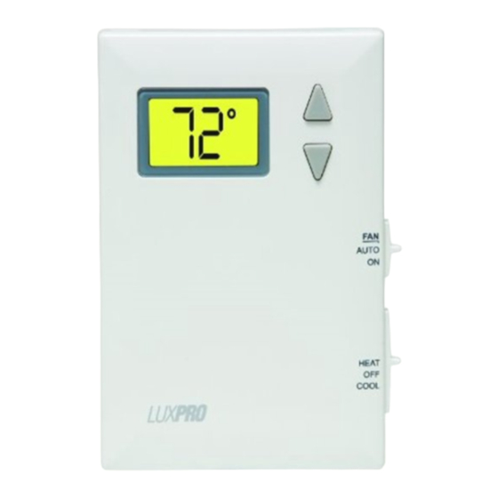
FEATURES
72
˚
Large Easy to
Read Backlit
Display
• Digital, Non-Programmable
• Easy To Install
• System Powered Only
• F / C Selectable Temperature Display
• Set Temperature Range 45°F to 90°F
• Fixed 5 Minute Minimum Run /
Off Time For Compressor Protection
• Clean, Attractive Design
• Adjustable Temperature Stops
• Large, Easy To Read Display with
LED Backlight
INSTALLATION
PLEASE READ ALL INSTRUCTIONS CAREFULLY BEFORE BEGINNING
INSTALLATION.
C A U T I O N :
This thermostat is protected against normal static electric
discharges. However, in extremely dry weather you should
touch a grounded metal object before touching the thermostat
to minimize the risk of causing damage to the unit.
TOOLS REQUIRED:
• #1 Phillips screwdriver (small - medium)
• Drill with 3/16-in. (4.8mm) drill bit
• Wire stripper/cutter
C A U T I O N :
Turn off electricity to the appliance before
installing or servicing the thermostat or any part
of the system. Do not turn the electricity back
on until the work is completed.
• Your thermostat is a precision instrument. Please handle it with
care.
• Do not short (jumper) across the electric terminals on your
heating or cooling equipment to test the system. This may
damage the thermostat and void your warranty.
• All wiring must conform to all applicable local codes and
ordinances.
• This thermostat is limited to a maximum of 1.5 amps, total
current; higher current may cause damage to the thermostat
THERMOSTAT LOCATION:
On replacement installations, mount the new thermostat in place of
the old one unless the conditions listed below suggest otherwise.
On new installations, follow the guidelines listed below.
1. Locate the thermostat on an inside wall, at about 5 ft. (1.5m)
above the floor, and in a room that is used often.
2. Do not install it where there are unusual heating conditions, such
as: direct sunlight, near a lamp, television, radiator, register,
fireplace, on a wall opposite a stove, or that carries hot water
pipes.
3. Do not locate in unusual cooling conditions, such as: on a wall
separating an unheated room, or in a draft from a stairwell, door,
or window.
4. Do not locate where air circulation is poor, such as: in a corner or
alcove, or behind an open door.
5. Do not locate in a damp area. This can lead to corrosion that may
shorten thermostat life.
6. Do not install the unit until all construction work and painting has
been completed.
REMOVING THE OLD THERMOSTAT:
1. Switch OFF the electricity to the heating/cooling equipment; then
proceed with the following:
2. Remove the front cover from your old thermostat. Most will
simply pull straight off, while others may be fastened by screws.
3. Take note of the letters printed near each of the wire terminals.
Attach adhesive labels (enclosed) to each wire for identification by
their terminal letter, not the color of the wire.
4. Make sure the wires do not fall back inside the wall. Remove and
label each wire one at a time, and do not allow the wires to touch
each other or any parts of the thermostat.
5. Loosen all screws on the old thermostat base, and remove it from
the wall.
52042
MOUNTING THE NEW THERMOSTAT:
1. Strip insulation leaving approximately 3/8 in. (10mm) of bare wire
on the ends, and clean off any corrosion present.
2. Fill the wall opening with non-combustible insulation to prevent
drafts from affecting the thermostat while in use.
3. Pull your new thermostat apart by applying pressure to the thumb
tab on the bottom edge of the unit, while pulling the front and
back halves apart from the bottom edge of the thermostat.
NOTE: If you are mounting the base to a soft material like
plasterboard, or if you are using the old mounting holes, the
screws may not hold. Drill a 3/16-in (4.8mm) hole at each
screw location, and insert the plastic anchors provided.
4. Route the wires through the large hole adjacent to the terminal
block, and hold the base plate against the wall. Position the base
for best appearance, and to hide any marks from an old
thermostat. Attach the base to the wall with the two screws
provided.
WIRING INFORMATION
** Complete heating or cooling system wiring can be found in the
WIRE IDENTIFICATION AND WIRING SCHEMATICS section of this
instruction sheet. The schematics show system components for
brand new installations or for un-referenced wires.
CONNECTING THE WIRES:
5. Clean bare wire ends must be inserted in between the
black clamp and the brass terminal as shown here.
6. Securely tighten all electrical terminal screws
(even unused ones).
Quick & Easy
SETUP OPTIONS
Temperature
Change
Buttons
Fan
Slide
Switch
FAN
AUTO
ON
Mode
Slide
Switch
EMER
HEAT
OFF
COOL
JUMPER SETTINGS:
There are two (2) headers (or jumpers) located inside the thermostat
at the rear of the circuit board. These settings can be changed from
their default values by removing its corresponding black jumper cap
and reinstalling the cap so that it is positioned on the adjacent pair
of metal pins. A change to ANY of the jumper settings will not be
recognized until power to the thermostat is removed for at least 2
minutes, and then power is restored again. This can simply be
accomplished by removing the thermostat from the wired back plate.
Each of these jumpers changes a different setup option. The choices
for these options are listed in a table printed on the circuit board,
and are also printed adjacent to each individual setting jumper.
JP1 - FAHRENHEIT OR CELSIUS DISPLAY FORMAT:
This setting controls whether the temperature is
shown in degrees °F or °C on the LCD display
screen.
JP2 - [B] OR [O] TERMINAL USAGE OPTION:
This setting determines how the thermostat will use
the shared B/O terminal connection on the back
plate. Select the "B" option to have the B/O
terminal powered while in heat mode, and un-
powered while in cool and off modes. Select the
"O" position to have the B/O terminal powered while
in cool mode, and un-powered while in heat and off
modes. If you are not sure which way to set this
option, consult the manufacturer of your heat pump
unit.
Once any optional jumper settings have been performed as described
in the previous section, ensure that at least 2 minutes have passed
since the thermostat has been last powered.
COMPLETING THE INSTALLATION
Install your new thermostat onto its base. To do this, start with the
bottom tilted out towards you at first, and line up the two holes in
the top of the thermostat with the two hooks on the top of the back
plate. Slowly pivot the bottom of the thermostat towards the back
plate and push firmly on the bottom half of the thermostat until it is
.
securely latched to the back plate. If the two thermostat halves do
not mate together easily, remove and try again. Do not attempt to
force them together if they do not appear aligned properly.
NOTE: Before use, remove the plastic film (if present) that is
protecting the LCD display screen.
Turn the electrical power back ON to both your heating and/or
cooling systems. Verify that both systems are operating properly.
When set to a high temperature, the heating system should provide
warm air after a short time in Heat Mode. Likewise, the cooling
system should provide cool air after a short time when set to a low
temperature in Cool Mode. Usually, sound from the heater and/or
cooling system units can be heard while either is running. Your
installation is now complete.
© 2 0 0 8 L U X P R O D U C T S C O R P O R A T I O N . A L L R I G H T S R E S E R V E D
UP
DOWN
JP1 (SCALE)
F
C
JP2 (B / O)
B
O
JP1
JP2
FRONT PANEL ITEMS
SYSTEM MODE SWITCH:
The MODE switch has 4 positions: EMER, HEAT, OFF, and COOL. In
the summer, set the switch to COOL to control cooling. In the
winter, set the mode switch to HEAT to control heating; set the mode
switch to EMER to control auxiliary heating only (if equipped). In
the EMER position, the heat pump compressor is disabled. When set
to OFF mode, the heating and cooling system will remain off.
FAN MODE SWITCH:
The FAN switch has 2 positions: AUTO and ON. In the AUTO
position, the operation of the blower fan is determined only by the
on/off cycling of the heating and cooling system. In the ON position,
the system's blower fan will be commanded ON continuously at all
times, even when the system mode switch is in the OFF position.
PUSH BUTTONS:
There are two push buttons to the right of the unit's display screen.
These are used to adjust the set point temperature.
OPERATING INSTRUCTIONS
TEMPERATURE ADJUSTMENT:
While in HEAT, COOL, or EMER modes, a single press on either the
UP or DOWN button causes the word "SET" to appear on the screen,
and the set temperature value on the screen to start flashing. When
flashing, the set temperature can be altered by pressing either the
UP or DOWN button once per degree of change, or by holding either
button for at least two seconds to automatically increment the set
temperature quickly in the associated direction.
Based upon the relationship of the set temperature to the displayed
ambient room temperature, the thermostat will engage the first stage
of either heating or cooling, if a temperature demand is present.
If there is a large thermal demand present which is greater than the
first stage of heating can accommodate, then a second stage of
heating (W2) will be activated, showing the word "AUX" on the
display screen. There is approximately a 4-minute delay that is
imposed between the activation of the first stage of heating, and the
second stage of heating.
DISPLAY ILLUMINATION:
Pressing either set temperature button will illuminate the display.
The light will remain on for approximately 12 seconds. While the
light is illuminated, pressing any of the 2 push buttons will cause the
light to remain on for approximately 12 more seconds.
MINIMUM RUN/OFF TIME:
This is determined by the thermostat, and controls the minimum
length of time that the thermostat must remain with Heat or Cool
either On or Off, before it will automatically switch to the alternate
On or Off state. This feature prevents rapid or short cycling, and
also provides compressor protection. The duration of this delay is
fixed at 5 minutes between on or off load changes.
ADJUSTABLE TEMPERATURE STOPS:
There are two independent set temperature stops: a maximum heat
set temperature, and a minimum cool set temperature. Each of these
temperature stops is user adjustable in one-degree increments. The
heat temperature stop prevents the set temperature from being
adjusted higher than the heat temperature stop value. The cool
temperature stop prevents the set temperature from being adjusted
lower than the cool temperature stop value.
To set the heat and cool temperature stops, place the system mode
switch in the OFF position. Press and hold the UP key while sliding
the mode switch from either OFF to HEAT (to adjust the maximum
heat set temperature), or from OFF to COOL (to adjust the minimum
cool set temperature). "Ht Lim" or "Cl Lim" will be displayed on the
LCD screen while you are setting the heat or cool limits respectively.
While in the adjustment mode for each of the temperature stops, use
the UP and DOWN buttons to adjust the limit value, just as you
would for adjusting the set temperature under normal operation.
NOTE: If no buttons are pressed for 4 seconds, the thermostat will
accept the limit value that was on the screen, and return to normal
F
operating mode, for the current mode switch position. Once,
complete, you should return to the adjustment mode again for both
C
heat and cool to confirm your desired settings for both temperature
modes have been accepted.
TECHNICAL ASSISTANCE
B
If you have any problems installing or using this thermostat, please
O
carefully and thoroughly review the instruction manual. If you
require assistance, please contact our Technical Assistance
Department at 856-234-8803 during regular business hours between
8:00AM and 4:30PM Eastern Standard Time, Monday through Friday.
You can also receive technical assistance online anytime day or night
at http://www.luxproproducts.com. Our web site offers you answers
to the most common technical questions, and also permits you to
email your questions to our technical support staff at your
convenience.
WARRANTY
Limited Warranty: If this unit fails because of defects in materials or
workmanship within three years of the date of original purchase, LUX
will, at its option, repair or replace it. This warranty does not cover
damage by accident, misuse, or failure to follow installation
instructions. Implied warranties are limited in duration to three
years from the date of original purchase. Some states do not allow
limitations on how long an implied warranty lasts, so the above
limitation may not apply to you. Please return malfunctioning or
defective units to the location from which the purchase was made,
along with proof of purchase. Please refer to "Technical
ASSISTANCE" before returning thermostat. Purchaser assumes all
risks and liability for incidental and consequential damage resulting
from installation and use of this unit. Some states do not allow the
exclusion of incidental or consequential damages, so the above
exclusion may not apply to you. This warranty gives you specific
legal rights and you may also have other rights which vary from
state to state. Applicable in the U.S.A. and Canada only.
Advertisement

Subscribe to Our Youtube Channel
Related Manuals for Lux Products LUXPRO PSDH021Ba


Summary of Contents for Lux Products LUXPRO PSDH021Ba
- Page 1 In the ON position, 52042 LUX PRODUCTS CORPORATION MOUNTING THE NEW THERMOSTAT: the system's blower fan will be commanded ON continuously at all Mt.
- Page 2 HEAT PUMP TERMINAL CROSS REFERENCE CHART (PSDH021Wa) ENGLISH - WIRE IDENTIFICATION AND WIRING SCHEMATICS TABLEAU DE RÉFÉRENCE CROISÉE DE BORNE DE POMPE À CHALEUR TABLA DE REFERENCIA PARA LA TERMINAL DE LA BOMBA DE CALEFACCIÓN HEAT PUMP BRAND CORRESPONDING TERMINALS TAPE OFF (NOT USED) TYPICAL 24 VOLT, SINGLE-STAGE HEAT PUMPS AND TYPICAL 24 VOLT, 2-STAGE HEAT / 1-STAGE COOL...
Need help?
Do you have a question about the LUXPRO PSDH021Ba and is the answer not in the manual?
Questions and answers