Table of Contents
Advertisement
Quick Links
Advertisement
Table of Contents

Related Manuals for Logitek BRIGHT-VU

Summary of Contents for Logitek BRIGHT-VU
- Page 1 Logitek BRIGHT-VU LED Audio Level Display Operation & Service Manual...
- Page 2 United States copyright laws and international treaty provisions. Logitek grants to you the right to use one copy of the embedded soft- ware in each Bright-VU meter you purchase. You may not rent or lease the software. You may not reverse engineer, decompile, disassemble, or cre- ate derivative works from the software.
-
Page 3: Table Of Contents
Bright-VU LED Meter INSTRUCTION MANUAL Table of Contents SECTION 1 — GENERAL INFORMATION 1-1 General Description ..........3 1-2 Electrical Specifications . -
Page 4: Section 1 - General Information
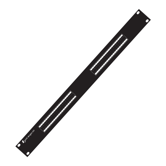
1-1 General Description 1-3 Instrument Identification The Logitek Bright-VU is a bargraph type audio The Bright-VU is identified by a model number and level meter featuring two LED bargraphs. Average a three or four digit serial number. The model number level is always shown and is displayed as a solid bar. -
Page 5: Section 2 - Preparation For Use
S/PDIF signals and cables. S/PDIF signals using RCA type plugs may be con- If the unit must be returned to Logitek, attach a let- nected to the input using an RCA to XLR adapter. ter to it showing the owner’s name and address. A de-... -
Page 6: Connecting Analog Input Models
60 Seconds of continuous fault 120 Seconds of continuous fault 300 Seconds of continuous fault The Bright-VU shield pins are bonded directly to the chassis at the connector and do not share any Peak Display Control ground paths with the internal circuitry. This allows ca-... -
Page 7: Section 3 - Operating Instructions
300 milliseconds per 20 dB. These ballistics conform the international standards with the exception that the Bright-VU peak attack time is slightly faster. 3-3 Using Alignment Tones The Bright-VU always displays the actual meas- ured values of the input signal. -
Page 8: Section 4 - Servicing
* * * * * * * IMPORTANT NOTE * * * * * * * * 4-1 General Information Do NOT remove or handle CMOS integrated cir- The Bright-VU is designed to need a minimum of cuits except in a grounded environment which is free maintenance for long trouble-free operation. Should of the risk of static electricity. -
Page 9: Analog Input Card
IC1. IC1 provides an additional -6 dB pad between its input and output. Each Bright-VU contains a ground isolated and fil- These pads allow +20 dBu input signals to be handled tered step-down power supply to create the necessary by the +/- 5 volt supply rails. - Page 10 IC5 and IC6 supply low noise regulated +/- 5 VDC to the analog portions of the cir- cuit. The digital part of the data converter gets its +5 VDC from the DSP control card. Page 10 ** Bright-VU Instruction Manual **...
-
Page 11: Section 5 - Replacement Parts List
SECTION 5 — REPLACEMENT PARTS LIST All replacement parts are stocked in depth at the Logitek factory. Most are also available through local electronic parts distributors. For your convenience in purchasing replacement parts locally, we include the following parts list. -
Page 12: Digital Input Card
PN-050-010-455 Integrated Circuits AES/EBU receiver CS-CS8412-CS +5 VDC regulator 100ma MO-MC78L05ACP Resistors 2200 1000 Switches SW1,2 2 position SPST dip lever CT-194-2MST Transformers AES/EBU SS-67129600 1 pc. Circuit card LG-272 Bright-VU Digital Input Page 12 ** Bright-VU Instruction Manual **... -
Page 13: Led Display Card
PN-MLSS156-3A 3-pin large socket PN-CE156F20-3A Power entry module/fuse holder SR-6200.4115 Switches Slide DPDT CK-L202-121MS02QE Transformers 10V 2.4A International SI-IF-24-16 1 pc. Circuit card LG-253A Super-VU Supply 1 pc. Power cord (North America) BE-17251 ** Bright-VU Instruction Manual ** Page 13... -
Page 14: Adc Input Card
PN-050-010-455 Ferrites FR1-3 Ferrite bead MU-BLM32A07PB Resistors R1,2 21k, .1% DL-RNC55H2102BS R3-7 4220, 1% R8,9 50K multiturn trimpot MP-CT9X503 R10,11 21K, .1% DL-RNC55H2102BS 4220, 1% R13-14 1 pc. ADC Input circuit card LG-264A Page 14 ** Bright-VU Instruction Manual **... -
Page 15: Section 6 - Manufacturers List
NIC Components Amityville, NY Nichicon Corporation Schaumburg, IL Neutrik Lakewood, NJ Panduit Corp. Tinsley Park, IL Quality Technologies Sunnyvale, CA Signal Transformers Co. Inwood, NY Schurter Inc. Petaluma, CA Schott Corp. Minneapolis, MN ** Bright-VU Instruction Manual ** Page 15... -
Page 16: Section 7 - Diagrams
SECTION 7 — DIAGRAMS Page 16 ** Bright-VU Instruction Manual **... - Page 17 ** Bright-VU Instruction Manual ** Page 17...
- Page 18 Page 18 ** Bright-VU Instruction Manual **...
- Page 19 ** Bright-VU Instruction Manual ** Page 19...
- Page 20 EXCEPT AS warranty extends to the original purchaser only. SPECIFICALLY PROVIDED HEREIN, LOGITEK LOGITEK will repair or replace, at its option, at its MAKES NO WARRANTY, REPRESENTATION, factory without charge professional equipment if a de-...
Need help?
Do you have a question about the BRIGHT-VU and is the answer not in the manual?
Questions and answers