
Subscribe to Our Youtube Channel
Related Manuals for Raveon RV-M7


Summary of Contents for Raveon RV-M7
- Page 1 RV-M7 Data Radio Modem Technical Manual Version E2 November, 2014 IP65 "Weatherproof” Version Raveon Technologies Corporation www.raveon.com...
-
Page 2: Table Of Contents
RV-M7 Technical Manual Table of Contents General Information about the RV-M7 ....................4 Congratulations! ................................4 NOTICE................................... 4 Safety / Warning Information ............................4 Blasting Caps and Blasting Areas ............................4 Potentially Explosive Atmospheres ............................5 Safety Training information: ............................5 Antenna Installation ................................ - Page 3 RV-M7 Technical Manual Packet Size .................................... 34 Key-On_Data ..................................34 Busy-Channel Lock Out ................................. 34 Addressing (Packetized Mode only) ..........................34 Addressing Basics ................................. 34 Group Numbers ..................................35 Hexadecimal Numbers ................................. 35 Setting A System-Wide Address ............................36 Broadcast Transmissions ..............................36 The Address Mask ................................
-
Page 4: General Information About The Rv-M7
The RV-M7 radio should be installed in safe, protected and restricted environment. While the RV-M7 does have an internal 3A fuse, there is no internal circuit breaker. The radio should be connected with an external circuit breaker. Blasting Caps and Blasting Areas... -
Page 5: Potentially Explosive Atmospheres
RV-M7-VB (150-174MHz 5 watts) 90cm FCC ID: SRS-M7-VB Raveon Technologies Corporation For vehicular roof top installation, the antenna must be placed in the center of the roof. Certifications The following certifications are specific to models RV-M7-Vx: Electromagnetic Compatibility and Radio Spectrum Matters (ERM):... -
Page 6: Fcc Compliance Information
European Automotive EMC Directive: 2004/104/CE Electrical Safety: EN 60950-1 :2006/A11 :2009 The following certifications are specific to models RV-M7-VB-x: Industry Canada: 8386A-RVM7VB FCC Compliance Information This device complies with part 15 of the FCC Rules. Operation is subject to the following two conditions: (1) This device may not cause harmful interference, and (2) this device must accept any interference received, including interference that may cause undesired operation. -
Page 7: Overview
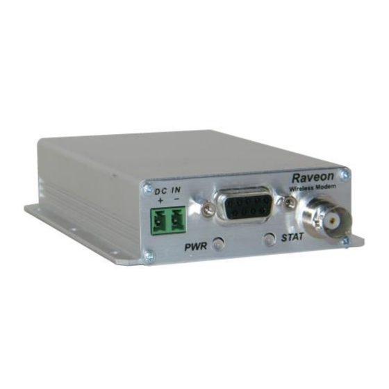
RV-M7 Technical Manual Overview The M7 RF data radio is a rugged high-performance, high-speed narrow-band data modem. It contains a receiver, a transmitter, and modem, creating an easy-to-use transparent data radio link. The M7’s user interface is asynchronous RS-232 data into and out of the M7 (CMOS level optional). -
Page 8: Specifications
..........................6 ounces (0.17kg) DC input voltage ............................10-16V DC Internal fuse ......3A mini blade. Littlefuse part number 0297003 or Raveon part, number 1X726-3 FCC ID Model RV-M7-UC-N...................... SRS-RV-M7-UC Model RV-M7-VB........................ SRS-M7-VB All other models for export or OEM use... -
Page 9: Model Numbers
= The band (V=136-174MHz, U=406-512MHz) = Sub band (A,B,C,…) = Channel Spacing (blank=12.5kHz, W=25kHz) = Options (-GX for GPS, -WX for waterproof enclosure) Other frequency bands, power levels, and channel spacing are available. Contact Raveon for your specific needs. Sub-Bands Sub-Band VHF (RV-M7-V…) -
Page 10: Electrical Inputs And Outputs
Pin 9 and ground to pin 5 of the 9-pin I/O connector. The M7 modem is supplied with a DC power cable, Raveon part number 1C738-1. Note: The M7 has in internal 3-amp mini-fuse (automotive type) to protect it and its power source against reverse voltage and serious hardware failures. -
Page 11: Rs-232/Eia232 Serial I/O Connector
RV-M7 Technical Manual RS-232/EIA232 Serial I/O Connector The RS-232 9-pin serial I/O connector is a female 9-pin D-subminiature connector having the following pins configuration. It is pinned out so that it may be plugged directly into a computer or PC’s 9-pin COM port. -
Page 12: Wx Weatherproof Version
RV-M7 Technical Manual Note: RS-232 signals use positive and negative voltages to represent digital 1s and 0s. A positive voltage is a 0, and a negative voltage is a digital 1. This pin-out enables the radio to be directly connected to a computer’s 9-pin serial port using a conventional 9-pin RS-232 serial cable. - Page 13 RV-M7 Technical Manual...
-
Page 14: Rs-232 Serial Cable For -Wx Version
RV-M7 Technical Manual -WX 5-Pin Circular I/O Connector Pin-Out A) RS-232 serial cable for –WX version The RS-232 serial cable uses at Hirose connector, part number HR30-6P-6S(71). B) RS-422 Connector Pin-Out on –WX 5-Pin Circular Connector If the RS422 option is installed in the M7 (-WX option), then the RS422 signals are connected to... -
Page 15: Optional Eia-485/Rs-485 Serial I/O
RV-M7 Technical Manual Optional EIA-485/RS-485 Serial I/O RS-485 Connector Pin Out RS-485 is a two-wire connection, with the pair of wires transmitting and receiving data. With the RS-485 enabled (ATIO 2 command), the 9-pin serial I/O connector on the front of the M7 is a female 9-pin D- subminiature connector having the following pins configuration. -
Page 16: Bias And Termination Resistors
RV-M7 Technical Manual If you wish to run the RS-485 in full-duplex mode using two M7s, the interface must be wired with two separate pairs of wires; A&B on one pair, and Out+ & Out- on the other pair. The M7’s RS-485 I/O circuit uses 3.3V logic to drive the lines, and the RS-485 pins are ESD protected to ±15kV and 7kV human body model... -
Page 17: Rs422/Eia-422 Serial I/O Connector
422 option for this to work. The M7’s hardware is identical to the RS-485 version, with the exception of two internal loop-back resistors. Raveon’s RS-422 I/O circuit uses 3.3V logic to drive the lines, and the RS422 pins are ESD protected to ±15kV and 7kV human body model RS-422 installations typically have a termination resistor across the In and the Out lines. -
Page 18: Low Power Mode (Lpm)
RV-M7 Technical Manual Serial out data comes out pins 3 and 7. Serial input data comes in via pins 4 and 8. Connect pin 5 to earth ground. Low Power Mode (LPM) The M7 modem, has the ability to be put into a low power sleep mode (SM). In SM the modem draws much less current from the DC input. -
Page 19: Setting A Parameter
RV-M7 Technical Manual pattern occurring in a stream of data entering the modem, there must be a pause in the data stream before the +++ as well as a pause after the +++ is sent. If either pause is missing, the modem will not enter the command mode. -
Page 20: Reading A Parameter
To see a list of all commands, type HELP. Radio Manager Radio Manager is a Windows XP/Vista software application that is used to configure Raveon's data radio products. It is compatible with all Raveon radio models, and provides configuration management, as well as programming assistance, diagnostic information, and a helpful "band... -
Page 21: Config Button
RV-M7 Technical Manual CONFIG Button If certain parameters within the modem are modified in a manner that causes the modem to cease functioning or if the user cannot enter the command mode via the “+++” method described above, there is a small push button internal to the M7 modem to assist in this case. -
Page 22: Exiting The Command Mode
RV-M7 Technical Manual Even though the serial baud rate reverts to 9600 baud when the CONFIG button is pressed and the IO port is RS-232, it will revert back to the settings programmed into the M7 modem once the Command Mode is exited. -
Page 23: Command Mode Commands
RV-M7 Technical Manual Command Mode Commands Factory Command Description Parameters Default Command Enable/Disable ARQ – When ARQ is enabled, this modem 0 (no AKCs ATAK will automatically send an ACK packet back to a modem that Range: 0 – 1 sent) sends it data. - Page 24 RV-M7 Technical Manual when the line is negated). 0 = Disable Set automatic on-line after ATDT command – 0: stay in command mode after exiting ATDTxxxx command. This is 1 = Enable ATCS the default configuration. 1: Exit command mode after 0 = Disable receiving an ATDTxxxx command.
- Page 25 RV-M7 Technical Manual current channel number. Group Number – Set/read the group number for this unit. 0 (ignore 0 means ignore the group number. 1-255 is a group identifier. ATGP 0-255 group Only M7s with the same Group Number will communicate numbers) together.
- Page 26 RV-M7 Technical Manual Protocol Select – The over-the-air communication protocol. ATMT Range: 0-2 0=Packetized mode, 2=Streaming data. Unit Address – Configures the individual; address for this unit. ATMY Each digit may be a 0,1,2,3,4,5,6,7,8,9,A,B,C,D,E,or F. Note: Range: 0000 - FFFF 1234 FF is interpreted as a group.
- Page 27 RV-M7 Technical Manual Frequency Offset. Used to set the radio on the center of the Range: -500 to +500 ATR8 radio channel. Number of retries. If this modem does not get an ACK back when it sends data, this is the number of times it will re-...
-
Page 28: Other Non-At Commands
RV-M7 Technical Manual 5 = TX all 1s 6 = Test Points ON 7 = Transmit CW 8 = Transmit 1010101… Read product temperature – Read the internal temperature ATTE -40 to +99 of the unit’s circuit board in degrees Celsius. -
Page 29: Factory Default Settings
SHOW None configuration. 5.11 Factory Default Settings For the UHF M7, model RV-M7-Ux, the main factory defaults are: Channel 1 (-UC model) ............464.500 MHz Channel 1 (-UA model) ............413.100 MHz Over-the-air baud rate: ............4800 baud, 2-level Serial port ................RS-232, 9600baud, N/8/1 Hardware flow control ............ - Page 30 RV-M7 Technical Manual...
-
Page 31: Using The M7 Modem - Packet Mode
RV-M7 Technical Manual Using the M7 Modem – Packet Mode This section describes the operation of the when it is in the Packet Mode of operation. Packet Mode is the factory-default operating mode. It is the easiest and most reliable mode of operation for a modem. -
Page 32: Setup
RV-M7 Technical Manual Figure 1 (Packet Mode of Operation) For operation of the modem in the streaming data, non-packetized mode, see the section Streaming Mode on page 41. The Packet or Streaming operation is configured using the ATMT command, with Packet Mode being the factory default. -
Page 33: Programming Channels And Frequencies
RV-M7 Technical Manual ATMY The ID of this unit. Default is 1234. ATMK The network address mask. Default is FFFF. ATDT The address of the unit this modem will talk to. Default is 1234. 6. Connect your serial data device to the 9-pin connector on the front of the modem. -
Page 34: Flow Control
RV-M7 Technical Manual utilization is only about 50%. But, if the serial port baud rate is set much higher, say 2-8X the over- the air rate, the channel utilization becomes near 100%. Because the M7 can handle serial-port data rate far in excess of the over-the-air rate, the efficiency of the M7 in Packet Mode is approximately the same as other brand modems that cannot operate in a Packet Mode —... -
Page 35: Group Numbers
RV-M7 Technical Manual interfere with each other. Also, some user application cannot tolerate receiving data that was not intended for it, and by setting the addresses in the modems properly, the system can be configured to allow reception of only data intended for the recipient. -
Page 36: Setting A System-Wide Address
RV-M7 Technical Manual its serial port. If it does not match, the receiving modem discards the data, and does not send it out the serial port. Setting A System-Wide Address If individual addressing is not needed in your system, there are two ways to ensure it is not used. -
Page 37: Listen Address (Version C21 And Higher Firmware)
RV-M7 Technical Manual ` Figure 2 (Address Filtering) M7 receives data over-the- M7 has Unit Address air to Destination Address yyyy xxxx M7 has Address “AND” them “AND” them zzzz Mask together together Compare the two results from these two ANDs... -
Page 38: Error Correction
RV-M7 Technical Manual Notes: This is the default configuration. All units have address 1234, and all modems will talk to all other modems with address 1234. Example 2 (a configuration that won’t work) Sending to Destination Address = 1236 Receiving Unit Address = 1234 Receiving Unit’s Address Mask = FFFF... -
Page 39: Store-And-Forward Repeating
RV-M7 Technical Manual The factory default condition is not to send or require ACK packets, so if you wish to use this mode, program the M7 to transmit ACKs with the ATAK 1 command. This will cause the modem to send an ACK anytime it receives data from another modem. - Page 40 RV-M7 Technical Manual Figure 3 Overview of Repeater Operation In the example shown in Figure 3 above, M7 is will communicate with all other modems in the system. It can directly communicate with H, and F. Because of propagation limits, it cannot...
- Page 41 RV-M7 Technical Manual Unit ID Destination Network Repeat Repeat Repeat Repeat (ATMY) (ATDT) Mask Source Source Destination Destination (ATMK) Mask Mask Addresses programmed into unit Repeater table programmed into unit 1000 1000 FF00 1010 1000 FF00 1020 FFFF 1000 FFFF...
- Page 42 RV-M7 Technical Manual There can be an issue with regard to store-and-forward repeating and busy channels, particularly on polled systems. Raveon’s M7 wireless modem has a number of provisions in it to make store-and- forward repeating work smoothly. For example, in the diagram above, assume A is the master station, and C is a remote station being polled.
-
Page 43: Using The M7 Modem - Streaming Mode
RV-M7 Technical Manual Using the M7 Modem – Streaming Mode This section describes the operation of the Streaming Mode of operation. This mode is selected with the command ATMT 2. Streaming Mode Operation In Streaming Mode, radio transmissions will begin whenever data enters the mode, and the transmission will continue as long as there is data to send. -
Page 44: Bit Errors
RV-M7 Technical Manual enters the modem. When the buffer is empty and there is no more data coming into the modem, it will automatically de-key the radio and go back into the receive mode. The M7 modem will send a hidden end-of-message signal to the receiving modem, thus avoiding any extra data bytes “dribble... -
Page 45: Setting The Over-The-Air Data Rate
RV-M7 Technical Manual Setting the Over-The-Air Data Rate The M7 has programmable over-the-air baud rates. The over-the-air rate is stored in register R2, and is programmed with the ATR2 x command, where x is a number corresponding to the rate. The are many possible baud rates, but not all rates may be used with all radio modem models. - Page 46 RV-M7 Technical Manual Other data rates of 0(800bps), 2(2400bps), 3(4800bps), and 7(9600bps) will work, but have a less optimal bit-error-rate vs. receive sensitivity. RV-M7-UC-W (wide-band version) For high-speed operation, set R2 to 5 (9600 baud). For best range (longest distance), set R2 to 1 (1200 baud) Other data rates of 0(800bps), 2(2400bps), 3(4800bps), 7(9600bps), and 6(19,200bps) will work, but have a less optimal bit-error-rate vs.
-
Page 47: Installation
RV-M7 Technical Manual Installation Secure the M7 modem using the four mounting holes on the side flanges of the unit. Connect a DC power source to the DC IN connection on the front of the modem. Use the supplied cable, and connect the RED wire to +, and the black wire to – (ground). -
Page 48: Debug Related Commands
RV-M7 Technical Manual The FCC website also offers a list of Frequency Coordinators. These are private organizations officially certified by the FCC to help you through the process, and who in most cases will handle the actual filing of your application. With few exceptions, you must apply for an FCC license through a Frequency Coordinator. - Page 49 RV-M7 Technical Manual 1.1.1.2 Packet Counter The packet counter mode will output packet count statistics once per minute. It will output the number of packets received in the last minute as well as the running total. T ATPE Begin counting and displaying the packet counters every minute...
-
Page 50: M7 Diagnostic Provisions
RV-M7 Technical Manual M7 Diagnostic Provisions 11.1 Overview of Diagnostics Internal to the M7 radio modem, is a powerful 32-bit microprocessor. Along with handing all aspects of radio modulation and demodulation, the microprocessor also maintains an extensive array of diagnostic information. - Page 51 RV-M7 Technical Manual Reset all statistics counters Statistic Read – Returns numeric values, comma separated, of all Run time display ST10 statistics as described in the ST command. screen...
-
Page 52: Atst Command
RV-M7 Technical Manual 11.4 ATST Command The ATST command, will return the following information: STATISTICS (packets received over the air with no bit-errors and correct address) Good RX Packets (over-the-air packets with bit errors that were discarded) With Bad CRCs (receptions that were aborted due to noise, CW jamming, lost signal…) -
Page 53: Atst3 Command
RV-M7 Technical Manual 11.6 ATST3 Command The ATST3 command, will return the time and date the firmware in the M7 was compiled. 11.7 ATST4 Command The ATST4 command will return internal timers that tell how long the modem has been powered up and running. -
Page 54: Calibration Commands
RV-M7 Technical Manual 12.2 Calibration Commands The following AT commands are used to calibrate the M7. Do not ever change these unless you have been factory trained to do so. Factory Command Description Parameters Default Command Symbol Peak Deviation – Set the peak FM deviation of the Range: -1000 –... -
Page 55: Tx Deviation
RV-M7 Technical Manual 2. The modem will now put out CW on the center of the channel. 3. Read the frequency offset with the ATR8 command. 4. Adjust the frequency to the center of the channel with the ATR8 command. You can use the “U”... -
Page 56: Skyline Compatibility
The M7 RF modem has built-in compatibility with a radio modem made by Sonik Technologies, Vytek Wireless, and Cal Amp called the SkyLine. In most applications, Raveon’s M7 modem can communicate with SkyLine modems, provided the M7 is properly configured. There are two versions of the Skyline, a wide-band version running at 9600 bps over the air, and a narrow-band version running at 5142bps over the air. - Page 57 RV-M7 Technical Manual Note: The maximum Permissible Exposure (MPE) for this product was computed using a 0dB gain antenna, and must be recalculated if a gain antenna is used. Height Try to locate the antenna as high above obstructions, vehicle, and buildings as possible.
-
Page 58: Appendix A. Serial Port Hardware
RV-M7 Technical Manual Appendix A. Serial Port Hardware 15.1 Serial Port Data and Handshaking Signals In computer terminology, the RF modem is considered a “Data Communications Equipment” device, or DCE. The user’s hardware that the modem is connected to is considered “Data Terminal Equipment”, or DTE. -
Page 59: Dtr
RV-M7 Technical Manual On this line the modem indicates to the DTE that it has received a carrier from a remote device. It will assert this signal any time there is a carrier detected. The modem may be configured to assert this when an RF carrier is detected (any on-channel RF, voice or data), assert it only when another RF modem signal is detected, or always assert it. -
Page 60: Null Modem Without Handshaking
RV-M7 Technical Manual 15.2 Null modem without handshaking Sometimes, a “Null Modem” cable may be required to connect the M7 modem to another device. The specific connections are very dependent upon the type of hardware and handshaking used, but the following sections should help in configuring a null-modem cable. -
Page 61: Compatibility Issues
RV-M7 Technical Manual Null modem with full handshaking (DB-9 Female shown. Same wiring for male-to-male cable) Connector 1 Connector 2 Function Signal ground 15.5 Compatibility issues The null modem cable with full handshaking does not permit the older way of flow control to take place. - Page 62 RV-M7 Technical Manual Normally, the Serial I/O connector operates like an RS-232 serial interface. If the MIMIC mode is enabled, the operation of the radio is modified to transmit the digital status of the INPUT0 and INPUT1 pins across the radio link, and output their status on the OUT0 and OUT1 pins.
-
Page 63: Troubleshooting
RV-M7 Technical Manual Troubleshooting Symptom: Unit will not receive Solution Verify that the modem is on the correct RF channel. If it is, the RX LED should blink every time another modem tries to transmit to it. If the RX LED does not blink when it should be receiving, it is on the wrong RF frequency. -
Page 64: Symptom: Long Delay Before Transmitting
ATL0 command. Solution Verify the internal fuse OK. There is an internal fuse in the RV-M7, protecting it from reverse- voltage and electrical failures. If the power LED does not blink or come on when DC is applied, check the fuse and replace it with the same type 3-amp mini fuse, and try again. -
Page 65: Mechanical
RV-M7 Technical Manual Mechanical... - Page 66 RV-M7 Technical Manual Limited Two Year Warranty If within 24 months from date of purchase, this Product fails conforms to Raveon Technologies Corporation’s (the Company) published specifications for the model purchased due to a defect in material or workmanship, Raveon Technologies Corporation will repair or replace it, at Raveon’s sole discretion.
- Page 67 RV-M7 Technical Manual Warranty service is available by mailing postage prepaid to: Raveon Technologies Corporation 2461 Impala Drive Carlsbad, CA 92010 - USA To obtain warranty service, include a copy of the original sales receipt or invoice showing the date, location, and price of purchase.
Need help?
Do you have a question about the RV-M7 and is the answer not in the manual?
Questions and answers