Table of Contents
Advertisement
Quick Links
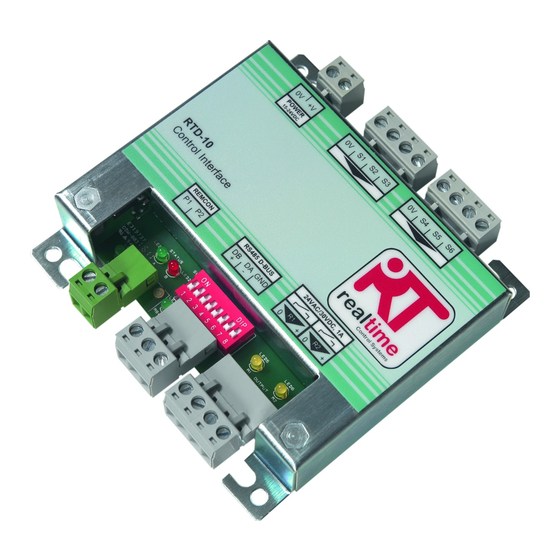
RTD-10 Control Interface v1.04
Installation and Operating Instructions
0V
+V
0V
S1
S2
S3
POWER
15-24VDC
RTD-10
100.00
Daikin Control Interface
REMCON
RS485 D-BUS
DB
P1
P2
DA
GND
+
-
SW1
ON
LED1
LED2
1 2 3 4
5 6 7 8
LED3
LED4
1
J2
100.00
22.00
All dimensions in mm
RTD-10 Description
The RTD-10 is a monitoring and control interface for Daikin VRV and Skyair
ranges of air-conditioners; and VAM and VKM ventilation units. The interface is
compatible with all units that have a P1,P2 remote controller network
connection and allows control of up to 16 units in a single group.
Control Functions
HARDWIRED CONTROL. Unit control can be achieved through resistance
inputs using resistor, potentiometer and volt-free contact inputs.
BMS INTEGRATION. Unit control can be achieved through 1-10V voltage
inputs integrated with BMS control outputs.
HEATING INTERLOCK. Units can be interlocked with external heating
systems.
DUTY/STANDBY. Multiple groups can be operated with rotating duty/standby
with fault and high temperature alarming.
MODBUS CONTROL. The RTD supports the Modbus Protocol for network
control and monitoring.
CUSTOM CONTROL. RTD interfaces can be supplied in custom configurations
to suit specific applications.
Warnings and Cautions
Do not exceed the specified fault relay ratings
Observe precautions for handling Electrostatic
Sensitive Devices
Mounting
0V
S4
S5
S6
MOUNTING PILLARS
R1
R2
0
+
0
+
LED5
LED6
The RTD-10 is supplied with 4
mounting pillars that can be used to
mount the interface within units with
compatible mounting holes
The RTD-10 can be mounted horizontally or vertically.
Power Supply
The RTD-10 requires a 15V to 24VDC power connection. Power can be
supplied from VRV indoor unit PCB X18A connection , a Skyair indoor unit
PCB X35A connection or VAM PCB X11A connection. A 1m cable and
connector is supplied with the RTD-10.
+V
0V
X18A
VRV
Indoor
PCB
P1,P2 Network
Terminals P1, P2 connect to the Daikin P1, P2 network. P1,P2 installation
should follow Daikin installation specifications. The RTD-10 can operate in
Master or Slave mode with any Daikin remote controller. Operation is also
possible without a remote controller being connected. Note that infra-red
receivers must be configured to operate in slave mode.
Indoor Unit
P1
P2
upto 16 units
Ø 5.00
88.00
78.00
SCREW MOUNTING
The RTD-10 can be mounted using
screws of up to 5mm diameter.
RED
RED
BLUE
BLUE
+V
0V
X35A
Skyair
Indoor
0V
+V
PCB
POWER
15-24VDC
Indoor Unit
Remote
Controller
(master)
P1
P2
P1
P2
Standard Control
The RTD-10 can be configured to operate in several different modes using the
configuration DIP switches SW1.1 to SW1.4. In Standard Control the following
combinations of modes are available:
Input
ON
Mode
Resistance
1 2 3 4
5 6 7 8
Relay R1
ON
Output
Unit Run
1 2 3 4
5 6 7 8
Unit Run
Setpoint
ON
Limit
No Limit
1 2 3 4
5 6 7 8
Standard Control: Resistance
In Resistance Control Mode the RTD-
10 Inputs allow individual control of
a/c unit operating parameters using
resistance values. Each input
corresponds to a specific unit setting
shown in the table below If an input is
left unconnected then the
corresponding setting will remain at
the default value.
S1
Setpoint
0..10kΏ : 16..32°C (22)
S2
Fanspeed
Low<=1.1kΏ, High=2.2kΏ, HighHigh*=3.3kΏ
S3
Mode
Auto<=1.1kΏ, Heat=2.2kΏ, Fan=3.3kΏ, Cool=4.7kΏ, Dry=6.8kΏ,
S4
Louvre
Swing<=1.1kΏ, 0°=2.2kΏ, 20°=3.3kΏ, 70°=4.7kΏ, 90°=6.8kΏ,
0V
+V
S5
On/off
On = Closed Circuit, Off = Open Circuit
POWER
15-24VDC
S6
Unlock
Lock All<=1.1kΏ, Lock Setpoint, Mode, On/Off= 2.2kΏ, Lock
Mode,On/Off=3.3kΏ, Lock On/Off=4.7Ώ, Local=6.8kΏ, Lock
Mode=9.6kΏ, Unlock>15kΏ
*HighHigh fanspeed operates if available, otherwise selects High fanspeed
S1 kΏ
0.3 0.9
1.5
2.1
2.6
3.2
R1
Run/
Run: SW1.3 OFF : Closed when unit switched ON
Defrost
Defrost: SW1.3 ON : Closed when unit in defrost
R2
Fault
Closed on any unit fault
RTD
Caution: Relays rated for maximum 1A, 24VAC/30VDC
P1
P2
Resistances should be within +/-250 ohms of the quoted value. Open circuit is R>200kΩ.
S1 in resistance mode is designed to be operated using a linear 10kΩ variable resistance.
It is recommended that volt-free contacts or switch mechanisms have gold plated contacts to ensure a low
resistance circuit when the switch is made.
S1 to S6 cables should be 0.5 to 1.0 mm
2
multi-stranded screened twisted pair. The screen should be earthed
at one end only. The maximum distance from the RTD-10 to the input source is 200m.
Voltage
ON
1 2 3 4
5 6 7 8
Defrost
ON
Operation
1 2 3 4
5 6 7 8
Limit 19 to 23
ON
1 2 3 4
5 6 7 8
S3
S6
S2
S5
S1
S4
0V
S1
S2
S3
0V
S4
S5
S6
ON
1 2 3 4
5 6 7 8
RESISTANCE MODE
9.7
3.8
4.4
5.0
5.6
6.2
6.8
7.4
7.9
8.5
9.1
Advertisement
Table of Contents

Related Manuals for Daikin RTD-10


Summary of Contents for Daikin RTD-10
-
Page 1: Warnings And Cautions
Observe precautions for handling Electrostatic S1 to S6 cables should be 0.5 to 1.0 mm multi-stranded screened twisted pair. The screen should be earthed at one end only. The maximum distance from the RTD-10 to the input source is 200m. Sensitive Devices... - Page 2 The RTD-10 can be configured to operate in Heating System Interlock mode In Voltage Control Mode the RTD-10 When the inhibit signal is closed circuit the RTD-10 will prevent the A/C unit to prevent A/C cooling or heating operation from conflicting with the operation Inputs allow individual control of a/c from operating.
- Page 3 The RTD-10 master will monitor all of the RTD slave devices discovered after RTD-10 RTD-10 RTD-10 power-up. If any of the RTD slave devices fail to respond the RTD-10 will raise CONFIGURATION a Level 2 alarm after 1 to 2 minutes. The Run/Standby configuration is selected using the RTD-10 DIP switch...
- Page 4 MODBUS CONFIGURATION ADDRESSING CONTROL VAM and VKM units can be switched on and off using the RTD-10 On/off input. Network 3 wire RS485 Control of VAM and VKM unit fanspeed and damper position from RTD-10 The RTD-10 has the facility to create control groups using multiple...
Need help?
Do you have a question about the RTD-10 and is the answer not in the manual?
Questions and answers