Robertshaw 300-224 Installation And Programming Instructions
Deluxe programmable thermostats
Hide thumbs
Also See for 300-224:
- Installation and programming instructions (40 pages) ,
- Installation & programming manual (10 pages) ,
- Specifications (2 pages)
Table of Contents

Subscribe to Our Youtube Channel
Related Manuals for Robertshaw 300-224


Summary of Contents for Robertshaw 300-224
- Page 1 Installation and Programming Instructions for Deluxe Programmable Thermostats Group LLC Air Marke6r Rrdge. 37656 Ter: 237-782 231-782-1783 ww amga cum Ernarr • rofofgamg au. KV7 0 erk art; ack Park 782 Fax Weh •...
-
Page 2: Table Of Contents
TABLE OF CONTENTS INTRODUCTION ..............STANDARD FEATURES ............THERMOSTAT LOCATION ..........REMOVING THE THERMOSTAT FROM THE SUBBASE ..DESCRIPTION OF THE DIP SWITCH FUNCTIONS ....9-11 COVER LOCK ..............REPLACING THE THERMOSTAT ON THE SUBBASE ....WIRING DIAGRAMS ............13-24 PROGRAMMING 7 DAY MODELS ........ - Page 3 POWER FAILURES ................29 OUTDOOR TEMPERATURE INDICATOR (OPTIONAL) ......29 PROGRAMMING 5/2 DAY MODELS ..........30-34 TYPICAL RESIDENTIAL SCHEDULE ..........30 PLANNING YOUR SCHEDULE ............31 SETTING THE CURRENT DAY AND TIME ........... 32 SETTING THE VVEEKDAY PROGRAM TIMES AND HEATING TEMPERATUPES ..32-33 =NG THE VVEEKEND PROGRAM TIMES AND HEATING TEMPERATURES.
-
Page 4: Introduction
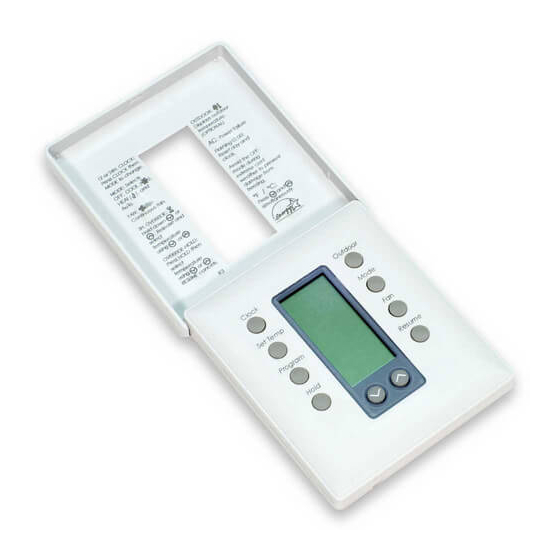
INTRODUCTION The Deluxe Programmable Thermostat represents the most advanced solid-state, microcomput- er temperature control on the market today. The thermostat incorporates state-of-the-art tech- nology packaged in an extremely low profile designer series case. Ultra-Touch controls are com- bined with an easy-to-read, full function liquid crystal display to provide the ultimate in user friendly operation of your heating and air conditioning equipment. - Page 5 FOR MODELS 300-224, 226, 230 display the Press to outdoor temperature (optional) Press to select heat/cod/auto/off. The word is displayed For 5 seconds. (Emergency heat for 300-22* Select for continuous fan or auto fan Press fp hold the current the hold setting.
- Page 6 FOR MODELS 300-225, 227, 229 display the Press ED temperature DLItd Der (Optional} select PS.9 heac uto/off. DO lre The word is displayed seconds. (Emergency heat for 300-227) 1O:32 Select f COntiRLIOLES auto tan Press to hold tre fall Or CUrrent setting.
-
Page 7: Thermostat Location
THERMOSTAT LOCATION To ensure proper operation, the thermostat should be mounted on an inside wall in a frequently occupied area of the building. In addition, its position must be at least 18" (46 cm) from out- side wall, and approximately 5', (1.5 m} above the floor in a location with freely circulating air of an average temperature. -
Page 8: Removing The Thermostat From The Subbase
REMOVING THE THERMOSTAT FROM THE SUBBASE 1. Insert a flat blade screwdriver or coin 1/8" into the slot located in the bottom center of the thermostat case and twist 1/4 turn. When you feel or hear a click, grasp the case from the bottom two corners and sep- arate from the sibbase as shown in the dia- gram at the left. -
Page 9: Description Of The Dip Switch Functions
2 Minute or 4 Minute Minimum On Times Keypad Lock Place the switch in the locked position to lockout all buttons except the OUTDOOR button. (300-224, 300-225, 300-229) Plenum Fan Switch OFF - Fan comes on immediately with heat (used on electric heat). - Page 10 (300-227, 300-229) Single or Multistate For eguipmtht with a single compressor 12 heat/1 cool for 300-227 or 1 heatil cool for 300- 229}, switch to single stage. For equipment with two compressors (3 heat/2 cool for 330-227 or 2 heat/2 cool for 300-229), switch to multistage. LED #1 (300-226, 300-227, 300-229) Switch ON will energize the LED light pipe at the top of the thermostat plus the filter indicator on the display.
- Page 11 (300-226, 300-227) Setting the Outdoor High and Low Temperature °Mance Points When using the optional Robertshaw remote outdoor sensor (Uni-Line If 10-529), you can select the outdoor balance points to loch-out the auxiliary heat andlor the compressor of the heat pump.
-
Page 12: Cover Lock
COVER LOCK You also may lock the cover down to prevent unauthorized access to the thermostat by adding the dear plastic lock (included in the installation bag). To install, remove the thermostat from the thermo subbase and place the dear plastic lock in the subbase as shown below. Replace the stat and close the cover. - Page 13 WIRING DIAGRAM - 300-224 lor,fi 10n,Cit LockiKI LI-Lx ,713, ADD .A1SPEFI FUR SINGLE TRANSFOPMER L me H FAT — Voltage COOL FA N Iran sf ormer 300-224 RirMeriferiv Grasp LLC 141 Knoarkamack Rd. Park Fudge. 14J 07 656 Tel: 201-7824 782 Fal 201-782-7783 Web: www.amgarraora Ema4: inkspamgarr.aarrp...
- Page 14 LInIrcked DE ii RC ....24VA0 supply from cooling Y ..Energizes the cooling equipment with a call 300-224 for cooling Fan is energized with a call for heating or 777 37 cooling or selected by pressing the FAN button in heating mode.
- Page 15 WIRING DIAGRAM - 300-225 Air Markeri g Greup LLC 17 Kinerlramack Rd Park Ridge. NJ Tet 27-7824 7783 www.amgarrear8 Ejse. inkspamgair.aartp 07858 72 Fa/ 782- Web:...
- Page 16 OUTPUT TERMINAL FUNCTIONS - W1 . Energizes on a call for first stage heat Y1 ....Energizes with a call for cooling ....Fan is energized with a call for heating or selected by pressing the FAN button ....Independent switching voltage' 300-225 24V .....
- Page 17 WIRING DIAGRAM - 300-226 Note 1: If jumper is removed, the R terminal may be used to accommodate independent switching circuits. (tricIT I (erice I Note 2.: Uriedced Lce.d This themiostat may be used Grar.ad cli•on with 24 Volt DC. The negative side of the used rm.
- Page 18 OUTPUT TERMINAL FUNCTIONS - W1..Auxiliary heat is energized as second stage heating or emergency heat Y1 ....Compressor is energized with a call for heating or cooling 11127. „Fan is energized with a call for heating or 7.1 a - fleheme cooling or selected by pressing the FAN arm.
- Page 19 WIRING DIAGRAM — 300-227 Note 1: If jumper is removed, a separate transformer must be used to power the loads. Note 2: This thermostat may be used with 24 Volt DC. The negative side of the DC supply must be wired to the 24V (c1 terminal. S-ral!.27:1 IlMocketl Icb,s1...
- Page 20 OUTPUT TERMINAL FUNCTIONS - Energizes auxiliary heat as second stage emergency heat 12..„„ ..Energizes compressor #2 on a call for second stage heating Of CDDlifIg W1 ..„ ..Energizes auxiliary heat as last heating or first stage stage emergency heat .Energizes compressor #1 First stage heat- 011 a Call for...
-
Page 21: Wiring Diagrams
WIRING DIAGRAM - Note 1: If jumper is removed, a separate transformer must be used to power the loads. Note This thermostat may be used with 24 Volt DC. The negative side of the DC supply must be wired to the 24V{C} terminal. 5,5. - Page 22 OUTPUT TERMINAL FUNCTIONS - Energizes auxiliary heat as second stage emer- gency heat Y2..„..Energizes mpreSSOr 42 On a ODD Or SE COnd stage heating or cooling .Energizes auxiliary heat as last stage heating or first stage emergency heat .Energizes compricsor #1 on a call for first stage w ezA atm.
- Page 23 WIRING DIAGRAM - 300-230 a,,. e.ti 1.0. cis Inden1 Iner :1,1 3W-230 Air Markeri g Group LLC 17 Kinarlramack Rd Park Ridge. NJ 207-782-7783 www.amgarreorn Erear inktgamgair.earP7 07858 297-7824782 Fel Web:...
- Page 24 OUTPUT TERMINAL FUNCTIONS — RC ..24VAC supply from cooling equipment transformer 11 01, ;11111. Dr, hylcx KOypad .... Energizes the cooling equipment with locked a call for cooling .... Fan is energized with a call for cooling of selected by pressing the FAN but- 300-230 El e I RS2 I RS1...
-
Page 25: Planning Your Schedule
PLANNING YOUR SCHEDULE (300-225, 300-227, 300-229) Your new Robertshaw programmable thermostat has been designed so that you can select either 2 program periods (Day and Night) or 4 program periods (Morning, Day, Evening and Night). The thermostat comes from the factory set for 4 program periods. To change this setting, please refer to the "2 Events or 4 Events Per Day"... -
Page 26: Programming 7 Day Models
SETTING THE CURRENT DAY AND TIME 1. Press the CLOCK Button. The display will flash a day of the week. 2. Press the s or t buttons until the current day shows. 3. Press the CLOCK button again. The display will flash the hour. (Note the AM/PM indicator.) 4. -
Page 27: Setting Your Program Times
SETTING YOUR PROGRAM TIMES Referring to your Schedule Planner. you now will enter the times for the program periods. 1. Press the PROGRAM button. The display will flash a day of the week. 2. Press the s or t buttons to select the day you wish to program. (We suggest starting with Monday.) 3. -
Page 28: Temperature Override
TEMPERATURE OVERRIDE Temporary Override (3 hours) You may change the temperature setting temporarily at any time without affect- ing the program. Press the a or t buttons. The current event temperature and made of operation will be displayed. Press the s or t buttons again to adjust the temperature. This temperature will be maintained for three hours. -
Page 29: Changing Fahrenheit (F) To Celsius ('C)
MODE button. The display will change automatically. POWER FAILURES This Robertshaw thermostat will maintain the program settings during any type of power failure. If power fails, AC will be displayed for 30 minutes. After 30 minutes, the display will go blank. If power is restored within the first 30 minutes, the thermostat will resume normal operation. -
Page 30: Programming 5/2 Day Models
TYPICAL RESIDENTIAL SCHEDULE (300-224, 300-226, 300-230) Weekday Time Weekend Time Temperature Settings AM/PM AM/PM HEAT MORNING „s il. ' 6:00 AM 8:00 AM COOL HEAT 9:00 AM 8:00 AM COOL HEAT EVENING 3:30 PM 8:00 AM -°- COOL HEAT NIGHT... -
Page 31: Planning Your Schedule
PLANNING YOUR SCHEDULE (300-224, 300-226, 300-230) To help save programming time, we suggest you use the worksheet below to set your specific program. We suggest you set your desired program times approximately 1 hour before the time required to reach the set temperature. Therefore, if you get up at 7:00 AM, set the morning temperature to come on at 6:00 AM. -
Page 32: Setting The Current Day And Time
SETTING THE CURRENT DAY AND TIME Before you set the current day and time, set the thermostat into the proper time mode press- ing the Daylight Saving Time (DST) button. If the thermostat has been installed during Daylight Saving Time, press and release the DST button until the clock symbol in the lower right corner of the display appears. -
Page 33: Temperatures
5. Press the s or t button to adjust the minutes. (Note the minutes are in increments of 10.) 6. Press the PROGRAM button. The heating temperature will be displayed. 7. Press the s or t button to adjust to the desired heating temperature. B. - Page 34 (Example: If you set the cooling temperature less than two degrees above the heating temperature, the thermostat will automatically maintain a two degree separation between heating and cooling by lowering the heating temperature. 4. Press the s or t button to adjust to the desired cooling temperature. Tr3 We TN Fr 5.
-
Page 35: Reviewing Scheduled Times And Temperatures
REVIEWING SCHEDULED TIMES AND TEMPERATURES To review your programmed schedules, repeatedly press and release the PROGRAM button. Each scheduled event will be displayed starting with the weekday start times and temperatures and ending with the weekend start times and temperatures. To cancel your review. simply press and release the RESUME button or wait 15 seconds for the thermostat to resume automatically. -
Page 36: Specifications
(300-224, 300-230) SPECIFICATIONS Rated Voltage ..............20-30 VAC. 24 nominal Rated A.G................08 Amps to 1.5 Amps continuous per Current output with surges to 4 Amps Max. Control Heating: 38 to 88°F in 1' Steps Range 5' to 30'C in 1' Steps Cooling: 60°... -
Page 37: Specifications
SPECIFICATIONS (300-225, 300-226, 300-227, 300-229) Rated Voltage ..............20-30 VAC, 24 nominal Rated A.C................050 Amps to 0.75 Amps continuous Current per output with surges to 3 Amps Max. Rated D.C................. 0 Amps to 0.75 Amps continuous Current per output with surges to 3 Amps Max. -
Page 38: Important Installer's Note
IMPORTANT INSTALLER'S NOTE FOR THE This thermostat is equipped with a transformer wiring fault indicator (located along the top left side of the thermostat). If the red light is ON when the wiring is complete, you must check the equipment to ensure that the transformers are wired in accordance with the diagrams provided on this sheet. - Page 39 TWO TRANSFORMER SYSTEM If the fault indicator is ON the transformers are out of phase. Switch the secondary wires of one of the transformers (NOT BOTH} and ensure the red light goes OFF. Separate RH and RC Wires Equipment Translemurs CoOny ns 6orme, Air Merirefirkg Greup...
- Page 40 This warranty does not apply in the event of misuse, abuse or as a result of unauthorized alterations or repairs. Robertshaw will not be li able for any consequential damages including, without limitation, damages resulting from defects, loss of use or misuse.
Need help?
Do you have a question about the 300-224 and is the answer not in the manual?
Questions and answers