
Related Manuals for ESPRIT X6

Summary of Contents for ESPRIT X6
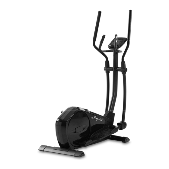
- Page 1 -ESP0034- Esprit X6 Cross Trainer OWNER’S MANUAL PLEASE CAREFULLY READ THIS ENTIRE MANUAL BEFORE OPERATING YOUR ELLIPTICAL!
-
Page 2: Safety Hints
Safety Hints WARNING Read all instructions before using this appliance. Do not operate elliptical on deeply padded, plush or shag carpet. Damage ■ to both carpet and elliptical may result. Keep children away from the elliptical. There are obvious pinch points and ■... -
Page 3: Assembly Pack Check List
Assembly Pack Check List STEP 1. #102- 5/16" × 3/4" Socket #53- M5 × 12 mm Phillips #43- 5/16" × 3/4" Button Head Cap Bolt (9 pcs) Head Screw (4pcs) Head Socket Bolt (4pcs) #44- 5/16” Flat #46- 5/16" ×1.5T #45- 5/16"... - Page 4 Assembly Pack Check List STEP 4. #46- 5/16" Split #30- 1/2" Nyloc #52- 5 × 12mm #44- 5/16” Flat Washer (2pcs) Nut (2pcs) Sheet Metal Screw Washer (2pcs) (2pcs) #29- 1/2" × 70mm # 98- 5/16" × 1" Carriage Bolt (2pcs) Button Head Socket Bolt (2pcs) #69- 19m/m Wrench (1pc)
- Page 5 Assembly Instructions STEP 1: Locate the Console Mast (9) and slide on Console Mast Cover (82) Make sure the cover is facing the correct direction, as shown below, before sliding onto mast. Install the wiring harness (94) into the bottom of the mast and out the top. Be careful when installing the console mast to the mainframe so as not to pinch or cut the wiring harness;...
- Page 7 STEP 2: Locate the Right Swing Arm (Upper) (8) and install it through the Swing Arm Bushing (23) and secure to the Lower swing arm (6). Use M5 Allen Wrench (68) to tighten 2pcs of 5/16” Button Head Socket Bolts (56) and 2pcs of 5/16" Nyloc Nuts (55) to the swing arm assembly.
- Page 8 STEP 3: Locate the Left Swing Arm (Upper) (7) and install it through the Swing Arm Bushing (23) and secure to the Lower swing arm (5). Use M5 Allen Wrench (68) to tighten 2pcs of 5/16” Button Head Socket Bolts (56) and 2pcs of 5/16" Nyloc Nuts (55) to the swing arm assembly.
- Page 9 STEP 4: 1. Locate Right side Pedal Arm Assembly (2) and install onto the pedal axle at the large rotating wheel at the rear of the elliptical. Use the M5 Allen Wrench (68) to tighten the 5/16” Button Head Socket Bolt (98), 5/16" Split Washer (46) and 5/16” Flat Washer (44).
-
Page 10: Key Functions
Console Key Functions START/STOP: 1. Starts & Pauses workouts. 2. Starts body fat measurement. 3. Holding key for 3 seconds will reset all functions and values to zero. DOWN: Decreases value of selected workout parameter: TIME, DISTANCE, etc. During the workout it will decrease the resistance load. -
Page 11: Workout Parameters
Functions: SPEED: Displays current training speed. Maximum speed is 99.9 KM/H or MILE/H. RPM: Displays current pedal rotations per minute. TIME: Accumulates workout time from 00:00 to 99:59. Or users can preset the target time desired. DIST: Accumulates the workout distance form 0.00 up to 999.9 KM or Mile. Or users can preset the target distance they want to reach. -
Page 12: Program Operation
More About Workout Parameters Setting Default Increment/ Parameter Description Range Value Decrement 1. When display is 0:00, Time will count Time 0:00~ 99:00 00:00 ± 1:00 2. When time is 1:00-99:00, It will count down to 0. 1.When display is 0.0, Distance Distance will count up. - Page 13 Pre-programs (P2~P13) Program profile ROLLING VALLEY FAT BURN RAMP STEPS OBSTACLE INTERVALS PLATEAU CLIMBING OFF ROAD HILL FASTREK...
- Page 14 There are 12 pre-set program profiles ready for use R OLLING, VALLEY, FAT BURN, : : : : RAMP, STEPS, OBSTACLE, INTERVALS, PLATEAU, CLIMBING, OFF ROAD, HILL, FASTREK. All program profiles have 24 levels of resistance. Setting Parameters for Pre-set programs Select one of pre-set programs using UP OR DOWN KEY then pressing ENTER KEY.
- Page 15 BODY FAT MEASUREMENT Setting Data for Body Fat Select “BODY FAT” using UP OR DOWN KEY then pressing ENTER. “Male” will flash indicating the Gender can be adjusted using UP OR DOWN KEY. Press ENTER to save gender setting & move to next setting. A Height of “175”...
- Page 16 Note: If your Pulse measurement is above or below (± 5) the TARGET H.R setting, the computer will adjust the resistance load automatically; it will check approximately every 10 seconds. If the heart rate signal disappears, the computer will keep the resistance load constant for 60 seconds then it will decrease the resistance load 1 level every 10s.
- Page 17 HEART RATE CONTROL Program Program profile There are 4 selection for target pulse: HRC- 55% TARGET H.R= 55% of (220-AGE) HRC - 65% TARGET H.R= 65% of (220-AGE) HRC - 75% TARGET H.R= 75% of (220-AGE) HRC - 85% TARGET H.R= 85% of (220-AGE) Setting Parameters for HEART RATE CONTROL Select one of the “Heart Rate Control Program”...
- Page 18 User Program Program profile 4 User programs allow the user to create their own personal program. Setting Parameters for User Program Select “User” using UP OR DOWN KEY then press ENTER KEY. The 1 parameter, “Time” will flash indicating the value can be adjusted using UP OR DOWN KEY. Press ENTER KEY to save value &...
-
Page 19: Parts List
Parts List DESCRIPTION O'TY Main Frame Pedal Bar Assembly (R) Pedal Bar Assembly (L) Cross Bar Lower Handle Bar (L) Lower Handle Bar (R) Left Swing Arm (Upper) Right Swing Arm (Upper) Console Mast Hand Pulse Sensor Arm (L) Hand Pulse Sensor Arm (R) Front Stabilizer Rear Stabilizer Crank Axle... - Page 20 DESCRIPTION O'TY Sleeve 5/16" × 20L_Carriage Bolt 20m/m_C Ring M10 × 1.25_Nut 3/8"-26UNF × 4T_Nut 3/8"-26UNF × 7T_Nut 5/16" × 3/4"_Button Head Socket Bolt 5/16" × 18 × 1.5T_Flat Washer 5/16" × 19 × 1.5T_Curved Washer 5/16" × 1.5T_Split Washer 1/4"...
- Page 21 DESCRIPTION O'TY Front Shroud (R) Front Shroud (L) Rear Shroud (R) Rear Shroud (L) Handle Bar Cover-A Handle Bar Cover-B Round Disk Round Disk Cover Console Mast Cover Pedal (L) Pedal (R) Pedal Arm Cover (L) Pedal Arm Cover (R) Power Bracket Console Mast End Cap M5-75L_Phillips Head Screw...
- Page 23 WARRANTY, SAFETY AND ASSEMBLY INFORMATION ESP0034 – X6 IMPORTANT Please read and retain this manual as it will assist with identification for parts and service. ------------------------------------------------------------------------------------------------------------ BOYLES FITNESS warrants their Cross Trainer to be free from defects in material and workmanship under normal use and service conditions.
- Page 24 This Esprit X6 Cross Trainer is warranted to be free from defects in material and workmanship under normal use and service conditions for a period of 6 months from the date of purchase of this article.
- Page 25 A service representative will then assist you in the appropriate action to be taken. For efficient processing of your enquiry please have proof of purchase, the date of purchase and the retailer name you purchased the item from, and the brand on the product.
Need help?
Do you have a question about the X6 and is the answer not in the manual?
Questions and answers