Table of Contents
Advertisement
Advertisement
Table of Contents

Summary of Contents for Silva s15
- Page 1 VHF DSC S15 CLASSE D DSC, NAVTEX, GPS...
- Page 2 Operation Manual Chapter Description Page Introduction Front Panel Description Front Back Of Unit LCD Display Fist Microphone/Controller Soft Keypad (0 – 9) General Operation Dual Watch Full Scan Memory Scan High / Low RF Output Power Selection Squelch Control Volume Control Channel 16 Channel Select Memory Channel Select...
- Page 3 Operation Manual Settings Backlight & Keypad Lighting Adjustment Contrast Adjustment Speaker Selection Tone Selection DSC Setting MMSI Setting Set Group ID Set Date And Time Set Manual Position Set Called Channels Set Directory Of Called MMSI And Vessel Names NAVTEX Setting 10.1 Station Selection 10.2...
-
Page 4: Introduction
Search And Rescue (SAR) information and other data for ships sailing within their service range. If the S15 is connected with a GPS, it will also display your vessels position and Universal Time Coordinated (UTC) and it can also give you the COG (Course Over Ground), SOG (Speed Over Ground), BTW (Bearing To Waypoint) and DTW (Distance To Waypoint) of your vessel. -
Page 5: Front Panel Description
2. Front Panel Description 2.1 Front 1. POWER SWITCH (ON) Press the (ON) button once on the front panel of the S15. To switch off, press (ON) again the S15 switch off. 2. CHANNEL MEMORY KEY (M+) The function of this key is to add or delete the currently selected channel from the scan memory. -
Page 6: Liquid Crystal Display (Lcd)
Insert the screw and tighten once again. Note: To ensure your S15 maintains its waterproof feature, please make sure the waterproof plastic washer is properly inserted before the screw;... -
Page 7: Lcd Display
Operation Manual 2.3 LCD Display 6 5 4 3 2 1 GROUP 1 Volume control is activated, the Bar indicates the volume level. Squelch control is activated, the Bar indicates the squelch level. Appears when the squelch opens. The radio is in receptive state (RX) and when receiving a signal. The radio is transmitting (TX). -
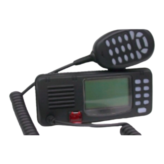
Page 8: Fist Microphone/Controller
Operation Manual 3. Fist Microphone/Controller The fist mike/controller has the microphone, Push to Talk (PTT) switch and Soft-keypad as illustrated below: 3.1 SOFT-KEYPAD (0 - 9) The telephone style keypad ITU 0 – 9 / A - Z is used for entering numeric data. - Page 9 Operation Manual ENTER KEY (ENT) Confirms the action. CLEAR KEY (CLR) Stop tasks and returns to main screen or returns to the last screen. ◄ / ► Key Moves the cursor position when setting. ▲/ ▼ KEY Use to select working channel (Up or Down). Can also be used to select stored working channels.
-
Page 10: General Operation
Operation Manual 4. General Operation The S15 is switched on by pressing the (ON) key once. If a GPS receiver and a NAVTEX receiver have been connected to the S15, the main screen will be as bellow: Press the (F) key on the front panel once to enter function selection mode. -
Page 11: Full Scan
Operation Manual Note that the radio will not transmit, nor will alternative channels be able to be selected while in dual watch mode. To restore normal operation press (F) key again or press channel (16) key. 4.2 FULL SCAN (FS) This function scans through each channel sequentially until a signal is detected above the squelch level set. -
Page 12: Squelch Control
Operation Manual 4.5 SQUELCH CONTROL In the main screen, press the (SQ) key on the front panel, the screen will be changed to the VHF screen. Squelch is used to adjust the receiver muting threshold (squelch) level. When pressed, the squelch level bar and “Sq”... -
Page 13: Channel Select
Operation Manual 4.7 CHANNEL 16 (16) Pressing (16) key will automatically select channel 16 on high power. Any active function (Dual watch scanning, DSC setting, log view, NAVTEX GPS setting etc) will be cancelled. 4.8 CHANNEL SELECT (▲ / ▼) Press ▲... -
Page 14: Receiving A Dsc Call
Operation Manual 5. Receiving A DSC Call When a DSC call is received, the radio will switch to the call log screen to display the details of the call and ring or sound the alarm depending on the nature of the call. The procedures that follow describe how to handle the types of calls that can be received. -
Page 15: Group Calls
Operation Manual Press the (ENT) key to stop the alarm (or ringing), and then listen for the voice message. 5.3 GROUP CALLS When a Group call is received, the radio will sound an alarm and display the details of the call, indicating whom it is from and the working channel as follows: Press (ENT) key to stop the alarm, then listen for the voice message or speak. - Page 16 Operation Manual Page...
-
Page 17: Sending A Dsc Call
Operation Manual 6. Sending A DSC Call Making a DSC call is very simple. First choose the call type (Routine, Safety, Urgency, Group or Distress Alert). If required, enter the destination and working channel and then send the call by pushing (ENT) key on the fist microphone/controller. -
Page 18: Routine Call
Operation Manual Press and hold the (DIST) key for about five seconds. A countdown to the transmission will be displayed then an alarm will sound. The Distress Alert transmission contains the following data: 1. The vessel’s MMSI; The vessel’s position (either from the NMEA0183 input, or manually entered);... -
Page 19: Urgency Call And Safety Call
Operation Manual Then enter a called vessel’s MMSI number with the keypad and select a working channel by pressing the ▲ or ▼ key on the keypad from the channel list. Press (ENT) key and the Radio will send a routine call. Then the radio will change to following screen and wait for a reply. -
Page 20: Group Call
Operation Manual Press the (ENT) key again to make the call, or press (CLR) for cancel. When the call is sent, the radio will be set to the working channel. Allow a few seconds for the stations receiving the call to switch to the working channel. -
Page 21: Log View
Operation Manual 7. LOG VIEW There are 3 different logs; routine log, distress message log and NAVTEX message log. To view the logs, press (MENU) key on the mike keypad, the MENU SELECTION screen will appear on the display as follows: Press ▲... -
Page 22: Distress Calls
Operation Manual If messages have been received, the screen will be as follows: The ◄ or ► keys are used to move back or forward through the log. Press (CLR) key to exit from the VHF ROUTINE LOG screen and go back to the LOG VIEW screen. - Page 23 Operation Manual If there have been no messages received, the screen will be indicated DISTRESS LOG NO ITEM and after a while automatically revert to the last screen. If messages have been received, the screen will be as follows: Use the ◄ or ► key to move back and forward through the distress log. The distress message screen is as follows: 7.3 VIEW NAVTEX MESSAGE Press ▲...
- Page 24 Operation Manual On the screen, the letter “N” indicates this message has not been read, the letter “W” indicates the message is a Warning message (A, B or C type message), and “S” indicates the message is a SAR message (D type message).
-
Page 25: Contrast Adjustment
Operation Manual 8. Settings Using the instructions listed below to set up user environment. 8.1 BACKLIGHT AND KEYPAD LIGHTING ADJUSTMENT Press “▲”“▼”on the microphone to select BACKLIGHT option and press (ENT) to obtain the following screen. Then, press “▲”“▼”to adjust the brightness of backlight. There are 5 levels of brightness. -
Page 26: Tone Selection
Operation Manual 8.3 SPEAKER SELECTING Using “▲”“▼”on the microphone to select SPEAKER and press (ENT) to obtain the following screen. Then, press “▲”“▼”to select internal, external or both speaker. Press (ENT) for confirmation and exit. 8.4 TONE SELECTION Using “▲”“▼”to select BEEP and press (ENT) to obtain the following screen. -
Page 27: Dsc Settings
MMSI of your vessel. If you have not entered an MMSI, you can still use the unit but the default MMSI is 000000000, and every time the S15 is turned on it will ask you to enter the MMSI number. -
Page 28: Set Group Id
Operation Manual To view your vessel MMSI, press (MENU) key on the mike keypad to select the MENU SELECTION screen. Press ▲ or ▼ key on the mike keypad to select the DSC SETTING screen as below: Press ▲ or ▼ key again to move the symbol ► on the screen to front of MMSI, and press (ENT) key to confirm. -
Page 29: Set Date And Time
Operation Manual Use the numeric soft keys to enter the GROUP ID numbers (8 numbers, the first number must be “0”). If a mistake is made, use the ◄ or ► key to move the cursor on the screen back and reset the number. Then press (ENT) key, the radio will ask for verification. - Page 30 Operation Manual If the position of the vessel cannot be obtained from a GPS via the NMEA 0183 input, this data can be entered manually. Press ▲ or ▼ key to move the ► symbol on the DSC SETTING screen in front of POSITION/UTC, then press (ENT) key to confirm, the POSITION/UTC screen will appear as follows: Use the numeric soft keys to enter required data, use numeric key (0) to...
- Page 31 Operation Manual Press ▲ or ▼ key to select add channel screen, then press (ENT) key to enter the WORK CHANNEL/ADD screen as follows: Press ▲ or ▼ key to change the selected channel, and press (ENT) key to accept. Then press ◄ or ► key to enter next channel. Press ▲...
- Page 32 Operation Manual Press ◄ or ► key to select channel (the 5th - the 9th channel) that is to be deleted, then press (ENT) key to accept. 9.6 SET THE DIRECTORY OF CALLED MMSI AND VESSELS NAME. The DIRECTORY screen is used to add, edit and entries from a list of up to 20 stored MMSI numbers, which can be recalled in the routine call screen.
- Page 33 Operation Manual To edit an existing entry, press ▲ or ▼ key to move symbol ► on the DIRECTORY screen in front of EDIT, then press (ENT) key to enter DIRECTORY-EDIT screen as follows: Use the ◄ or ► key to select the number of the entry. Then press (ENT) key.
-
Page 34: Station Selection
Operation Manual 10. NAVTEX Setting To limit the number of message displayed in the NAVTEX log you can select what station and also what type of message you wish to select. 10.1 STATION SELECTION Press (MENU) key to enter the MENU SELECTION screen then press ▲ or ▼... -
Page 35: Message Selection
Operation Manual 10.2 Message Selection Press ▲ or ▼ key to move the ► symbol on the NAVTEX SELECTION screen in front of MESSAGE SELECTION, then press (ENT) key to enter the MESSAGE SELECTION screen as follows: Press ▲ or ▼ key to move the ► symbol on the screen in front of the message category that you wish to inhibit, then press ◄... - Page 36 Operation Manual If YES, press (ENT), ALL messages will be clear and go back to NATEX SELECTION screen. Page...
-
Page 37: Gps Navigation Setting
Operation Manual 11. GPS Navigation Settings To display the vessels position and navigation information, the S15 must be connected to a GPS and waypoints must be entered. Press ▲ or ▼ key to move the symbol ► on the MENU SELECTION in front of GPS NAVIGITION. -
Page 38: Set Waypoint
Operation Manual The “waypoint number” represents the number of waypoints. You can find the “waypoint number” under the directory of “Waypoint Overview”. For example, if the waypoint number shows “05”, it means that there are 5 waypoints stored. Please note that the maximum storage for waypoints is 50. -
Page 39: Review Waypoint
Operation Manual If need enter the next waypoint, press (ENT) key, or press (CLR) key to return back to GPS NAVIGITION setting screen. 11.3 Review Waypoint To review the waypoint position, press ▲ or ▼ key to move the symbol ►... - Page 40 BTW (Bearing To Waypoint), DTW (Distance To Waypoint) The screen is as below: When S15 is not connected to GPS antenna, the point A will indicate “NO GPS” and the values of COG, SOG, BTW and DTW will show zero.
-
Page 41: Insert Waypoint
Operation Manual When vessel gets to the current waypoint, the next numerical waypoint automatically becomes the current waypoint. As long as waypoints are entered in a strict numeric sequence this allows a simple route to be created. 11.5 Insert Waypoint Press ▲... -
Page 42: Delete Waypoint
Operation Manual Enter position of the inserted waypoint and name, then press (ENT) to confirm. 11.6 Delete Waypoint Press ▲ or ▼ key to move symbol ► on the GPS NAVIGATION screen to front of DEL WAYPOINT, then press (ENT) KEY to confirm, the DEL WAYPOINT screen will appear on the display as below. -
Page 43: Technical Specifications
Operation Manual 12. Technical Specifications Power supply DC 12 V +30/-10% Channel capability 57 international channels UK: includes M1 (previously 37) and M2 Frequency Resolution 25KHz Method of frequency generation synthesizer Dimension 175(W) × 79(H) ×130(D) mm Weight 1175 grams 12.1 RECEIVER Multi Channel Receiver 1. -
Page 44: Channel 70 Monitor General Specification
Operation Manual 12.2 CHANNEL 70 MONITOR GENERAL SPECIFICATION 1.Frequency CH70 (156.525MHz) 2.Sensitivity ≤0dBµEMF for 20dB SINAD 3.Bandwidth 16KHz 4. First IF frequency used 17.9MHz 5. Second IF frequency used 455KHz 6. Adjacent Channel Selectivity ≥70dB 7. Spurious response Rejection ≥70dB 8. -
Page 45: International Vhf Marine Channel Chart
Operation Manual 13. International VHF Marine Channel Chart Function Transmitter Receiver Mode Ship Ship Channel Channel Assignment Frequency Frequency Ship Shore 156.050 160.650 Public Correspondence, Port Operation 156.100 160.700 Public Correspondence, Port Operation 156.150 160.750 Public Correspondence, Port Operation 156.200 160.800 Public Correspondence, Port Operation 156.250... -
Page 46: Installation
14. Installation 14.1 Unit Installation The S15 should be sited so that engine noise and vibration or other background noise does not make it difficult for the operator to hear. It is recommended that it is not installed where it will be exposed to continuous direct sunlight as this will eventually damage the LCD display. -
Page 47: Antenna Installation Recommendations
Operation Manual On the back of the case of S15 there is a antenna socket, a power cable socket and a jack socket for an external speaker / the GPS input and NAVTEX input (Fig D). Fig D The S15 requires a 12v DC supply to operate, this lead should be connected to the vessel’s power supply (the red wire is positive, black is negative),... - Page 48 Operation Manual As the range of VHF signals are governed by line of sight, the antenna should be placed as high as possible, while remaining clear of any metallic objects that could influence the resonance of the antenna. The most popular antennae for marine use are 1m (3ft 3in) long. On sail boats these are usually mounted at the masthead, where the length of the antenna keeps it clear from the navigation lights and wind vanes etc.
-
Page 49: Supplied Parts
Silva’s option, within a reasonable time after receipt of the product. This Warranty does not however cover defects or damage caused by unauthorized... -
Page 50: Declaration Of Conformity
Operation Manual 17. Declaration of Conformity Silva UK Ltd. Fleming Road, Kirkton Campus, Livingston, EH54 7BN, SCOTLAND. declare that the product identified below complies with the essential requirements of Council Directive 99/05/EC according to the conformity assessment procedure laid down in Annex IV of the Directive. - Page 51 Operation Manual 0191 Page...
Need help?
Do you have a question about the s15 and is the answer not in the manual?
Questions and answers
Will not switch on